Advanced Sheet Metal Design Using NX Cad Challenge_2_Box Assembly
SHEET METAL BOX ASSEMBLY DESIGN
OBJECTIVE:
Learn to design a sheet metal Box Assembly in industrial manner by using Siemens NX.
INTRODUCTION:
Sheet metal parts are widely used in machinery, enclosure, brackets, and automobile due to its various advantages. The parts are normally manufactured with break press. Sheet metal is nothing but the thin sheets made from metal of size ranging from 0.5 to 6mm. In this project I used NX CAD tool for designing the sheet metal bracket. NX CAD is used as design tool in more than 85% of the sheet metal industries.
DESIGN METHODOOLOGY:
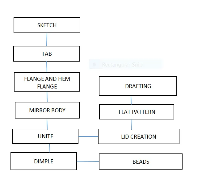
Box assembly is designed by keeping industrial procedure in mind to follow the design intent. The design methodology used for this project is summarized in below flowchart.
DESCRIPTION:
All the features used during designing the box assembly are described below. Some of the features were used repetitively at different instances.
Sketch:
For creating any sheet metal surface, we have to first make a sketch. So, I started with creating simple rectangular base sketch for creating the tab. Other than tab, various sketches are also made on different planes or faces for creating other different part during designing.
Tab:
Tab is the first parent feature in sheet metal designing using Siemens NX tool. All the other feature are usually based on tab. In this casing design, I created the tab by using the sketch on XY plane having dimensions of 150*200.
Flange:
Flange is used to add extra material to the existing edge at any angle and of any size. For this project of box assembly design, I added four flanges on different edges, firstly I added two flanges with 200 mm length normal to the XY plane and then another two flanges with length of 70 mm were added normal to XZ plane.
Closed corner:
Close corner feature is used to close a corner where two adjacent flanges meet by extending the bends and flanges. For this box assembly I used the closed corner feature twice to close the open corners at the bottom side of the flanges.
Flange for fastening:
For fastening or connecting the two flanges on side of box assembly I first created a flange without length and then another flange having dimension of 6.5 mm length with outside bend.
Hem flange:
Hem flange feature is used to modify the model by folding the edge of a flange. The main purpose of this feature is to increase the stiffness and for safe handling. For this box assembly I created the hem flanges with 0.5mm bend radius and length of 4 mm.
Mirror body:
As of now half part of the box assembly was designed remaining half part was designed by using mirror body feature, which saves lot of time. I used to mirror body feature to mirror the half body about YZ plane.
Unite:
Unite feature is used to combine two different bodies which are in contact. I used unite feature to combine the body before the mirror and after the mirror feature.
Dimple:
Dimple is the feature that lifts the area of model inside the sketch that simulates a stamping tool. Generally, it helps to strengthen the flat structure. For this box assembly I first created an appropriate sketch and then I used dimple feature to create the final dimple on one side of box assembly. Same dimple was mirrored to the other side of box.
Beads:
Beads are similar feature like dimple the only difference is that by using dimple we lift an area while in bead we lift the contour of the sketch. It also added to strengthen the component. For this project, one small bead was created near the top left corner having diameter of 15 mm. then it was mirrored along the XZ plane and YZ plane to obtain the four beads on each corner.
Hem flange:
At this stage hem flange is used to create rounded edge at the top which helps in easy handling.
Lid creation:
For creating the lid for the box, a datum plane was created at a distance of 202 mm from XY plane. The sketch was created by taking the reference of the edges from the top view of the box design. Then the base tab was created with the sketch to create the lid.
Flanges:
For closing box with proper alignment flanges having web length of 3 mm were added to both sides.
Break Corner:
Break corner feature is used to smoothen or chamfer the sharp edges of the sheet metal part. This action helps to prevent the stress concentration and fracture breaking. For this box assembly I used blend with 10 mm.
Unbend:
Unbend feature is one of the most powerful feature in NX. In industry we have to mark all the marking and sketch on flat sheet metal before it went to actual operations, so this unbend feature allow us to do that activity in Siemens NX software. For this project of box assembly design, I used this feature 2 times to mark the further operations/sketches.
Normal cutout:
Normal cutout feature use to Cut material by projecting a sketch onto the model and then removing material perpendicular to the faces intersected by the projection. For this box assembly I used normal cutout feature to remove two rectangular area which leads to forming the hinge barrels on both sides.
Rebend:
Rebend feature is used to restore the unbend feature to its previous bent state along with any features added after the unbend feature. This is done by using rebend feature and selecting all the bends carefully in order they unbended.
Mirror body:
After that the body of the hinge was mirrored about YZ plane and similar one formed in the other side.
Flat Pattern:
Flat pattern feature allows us to covert 3D sheet metal component into 2D form in Siemens NX software. By using this flat pattern feature we can easily avoid error like interference or collision.
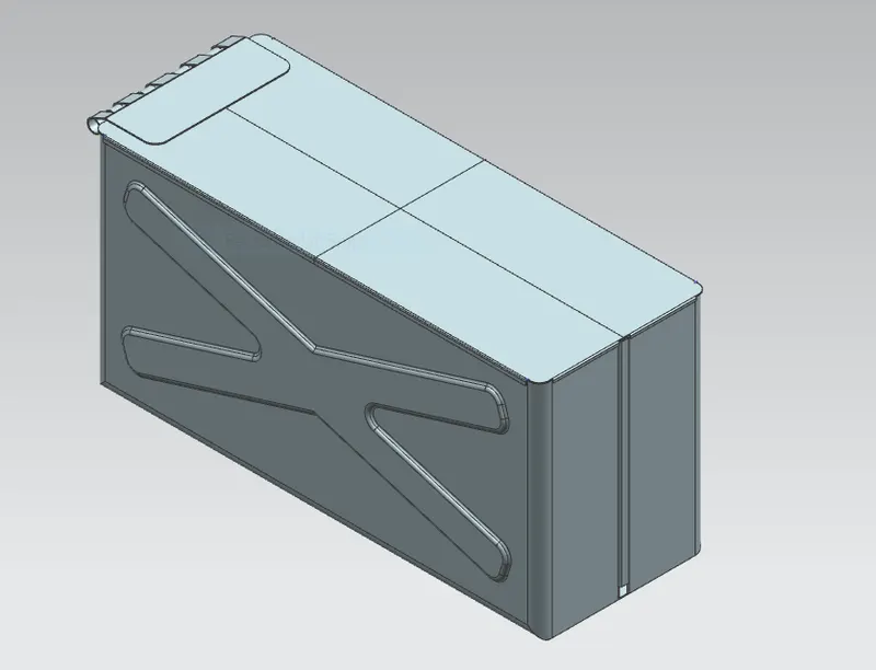
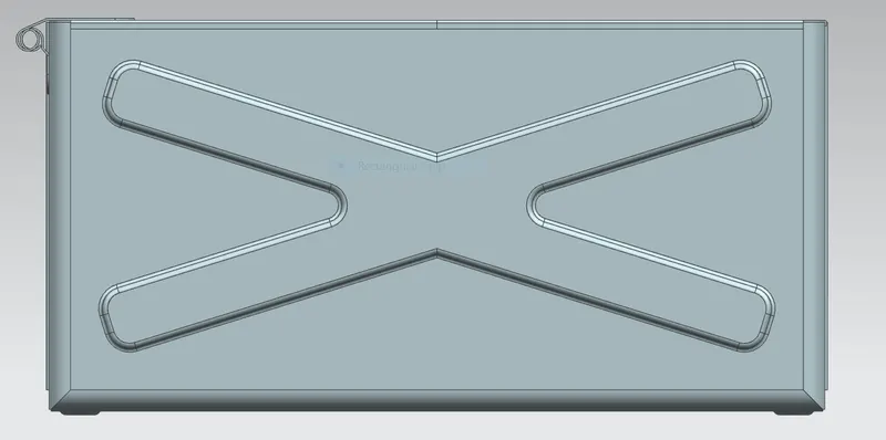
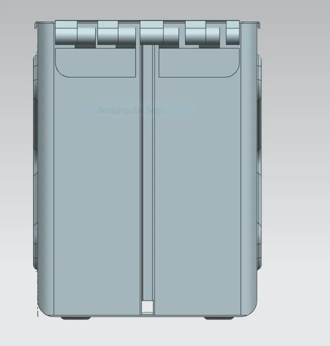
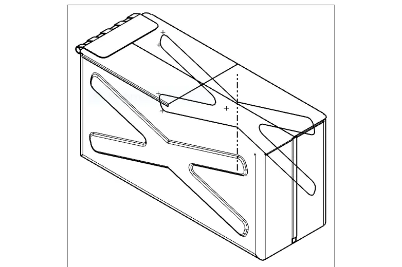
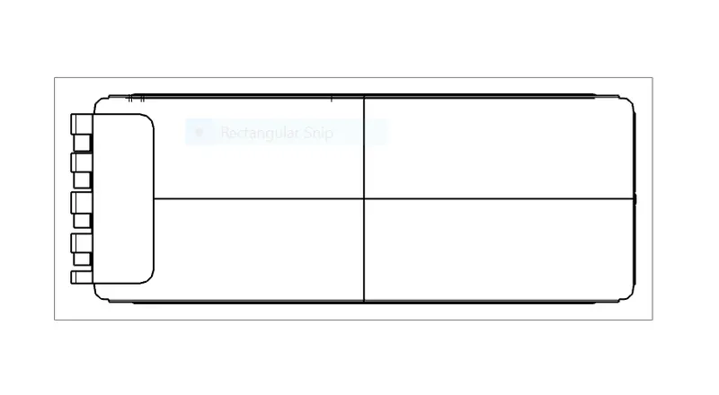
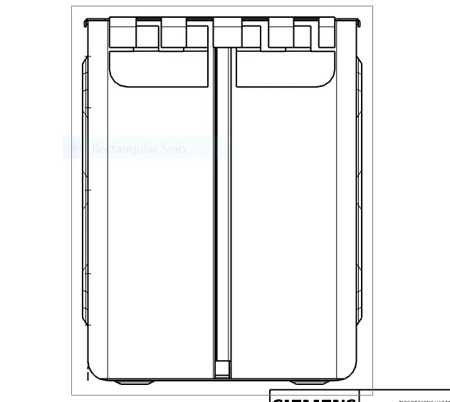
ISOMETRIC,FRONT AND SIDE VIEWS:
DRAFTING:
Conclusion:
Successfully learn to design a sheet metal Box Assembly in industrial manner by using Siemens NX.