Advanced Sheet Metal Design Using NX Cad Challenge_6_Bracket
Advanced Sheet Metal Design Using NX CAD- Bracket Design
OBJECTIVE:
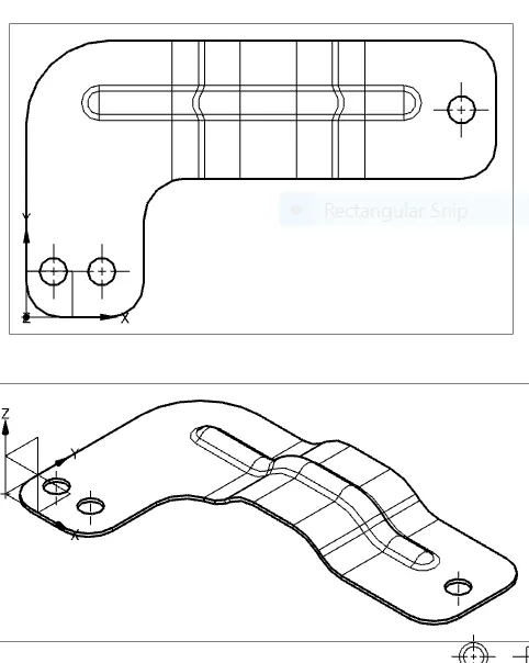
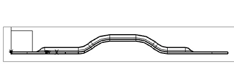
The main objective of this project is to design a sheet metal BRACKET in NX cad sheet metal application workbench. Also, to perform the drafting for the bracket part.
INTRODUCTION:
With NX sheet metal CAD tools, you can apply standard values, such as material thicknesses and bend radii, based on industry or company best practices. With folding and unfolding capabilities, you can work with models at any stage of the fabrication process. NX sheet metal software creates accurate flat patterns for documentation and manufacturing.
DESIGN METHODOLOGY:
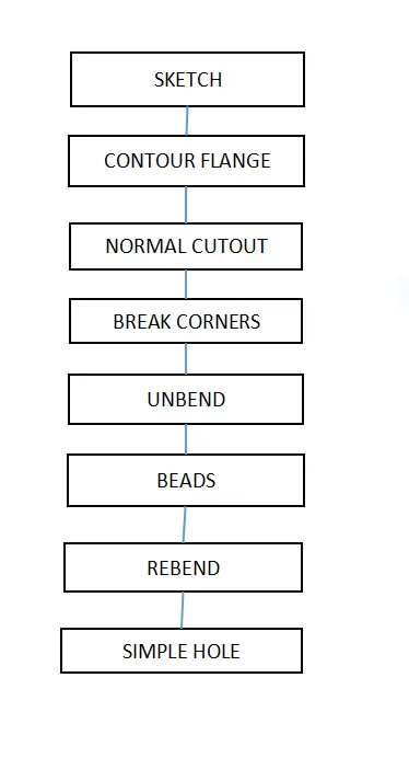
DESCRIPTION:
1.Sketch:
We use its tools to create a base sketch. (for eg: Rectangle, Circle, Line, etc.)
2.Contour flange:
In Siemens nx sheet metal contour flange command use to create a base feature by extruding a sketch along a vector, or adds material by sweeping a sketch along an edge or chain of edge.
From the menu: Insert -> Bend -> contour flange.
3.Normal cutout:
Using the NORMAL CUTOUT tool we remove the material from the required location.
4.Break corner:
Break corner and chamfer tools are used to make some changes over sheet metal body. Both the tools provides a different activity in creation of the parts.
Rounds or chamfers a sharp corner of a tab or flange. Here by using this tool we can do two different operations.
One is Forming Bend to part and secondary is Forming chamfer.
Bend: Completely formed with radius and creates smooth edges.
Unbend:
As the tool name indicates the bend tool is used to bend the sheet metal bodies and the unbend is viceversa of the bend tool,It is to unbend the bent regions.
Bead:
This tool is used to create a punch formation on the selected region on the body with smooth curvature on the edges.
Also we create circular projections with help of the BEAD command.
Re-bend:
As the tool name indicates the bend tool is used to bend the sheetmetal bodies and the re-bend is viceversa of the bend tool, It is to re-bend the un-bended regions.
Simple hole:
In the siemens nx modeling, hole command use to create a hole on one or more solid bodies in a part or assembly with option for counter-bored, countersunk, and threaded.
siemens nx modeling hole command make position point by point option.
siemens nx modeling hole command make position point by sketch section.
create a Simple hole in nx.
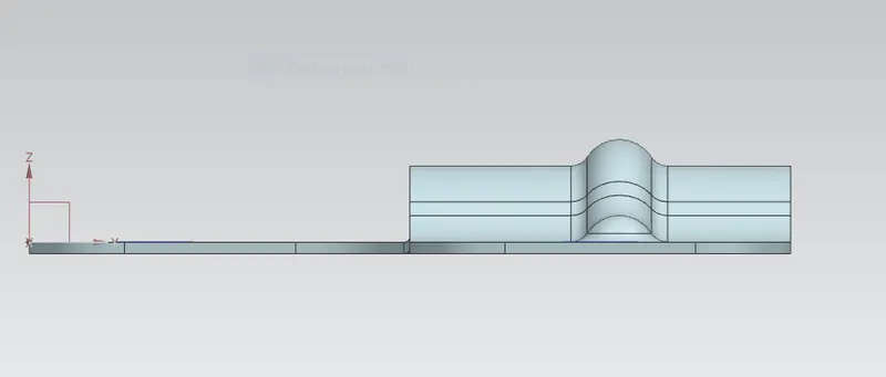
ISOMETRIC,FRONT AND SIDE VIEWS:
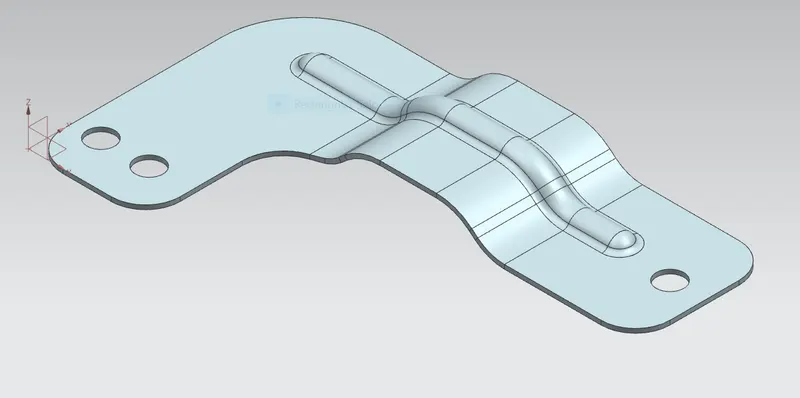
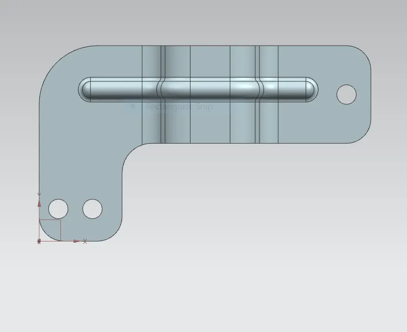
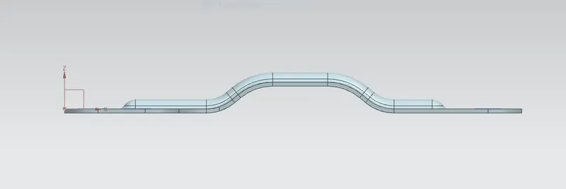
DRAFTING IMAGES:
CONCLUSION:
The bracket of the sheet metal is designed on the Siemens NX10.0.Tools and features were learned in bracket