Radar Mast & Final Assembly of Yacht
Radar Mast & Final Assembly of Yacht
Aim:
- To model Radar mast using Solidworks.
- To assemble the Yacht parts.
Radar Mast:
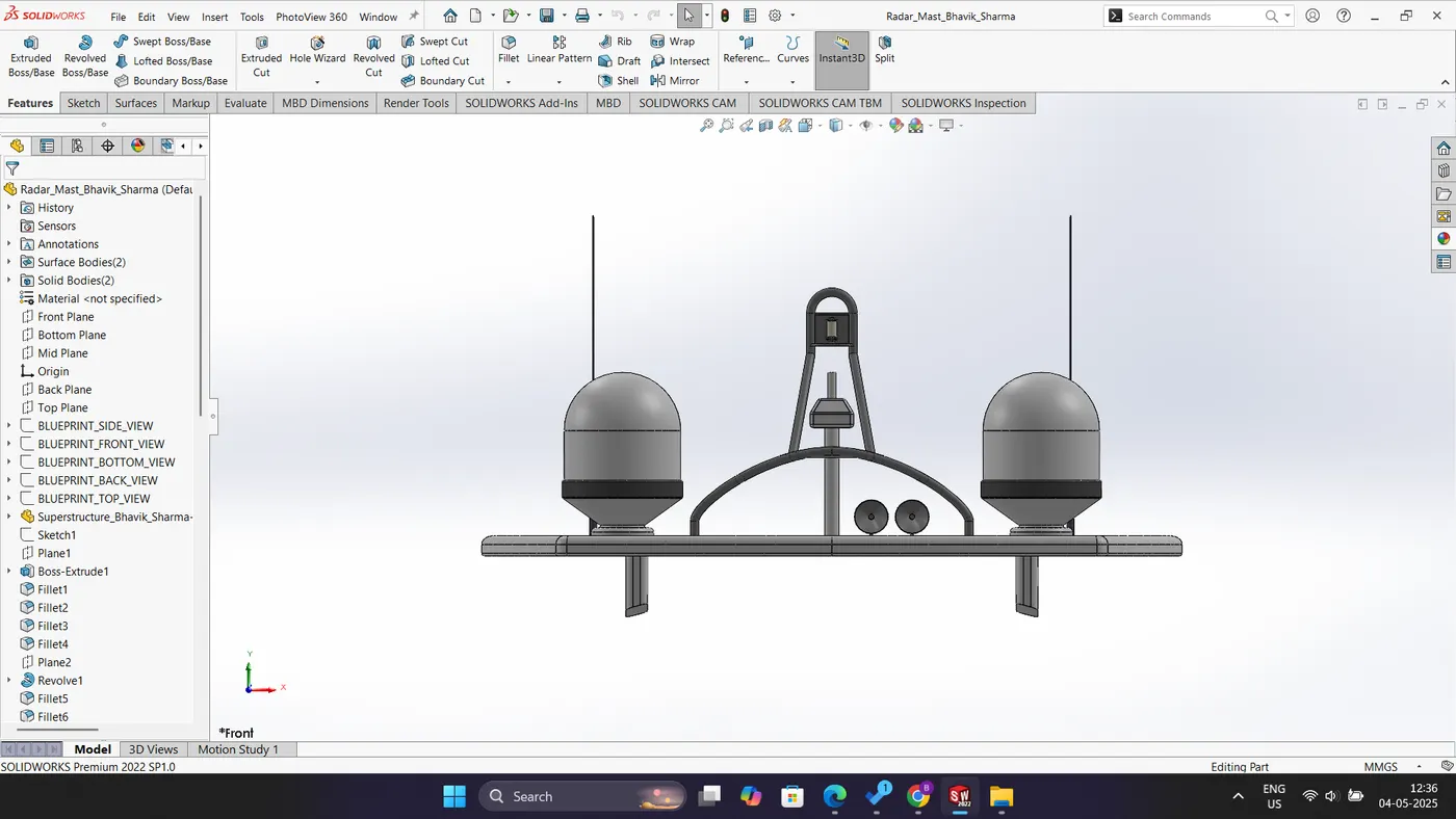
Fig: Front View
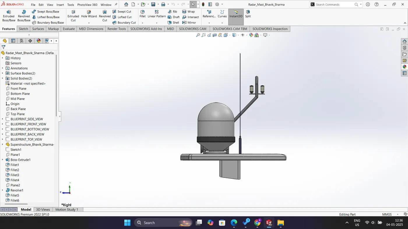
Fig: Side View
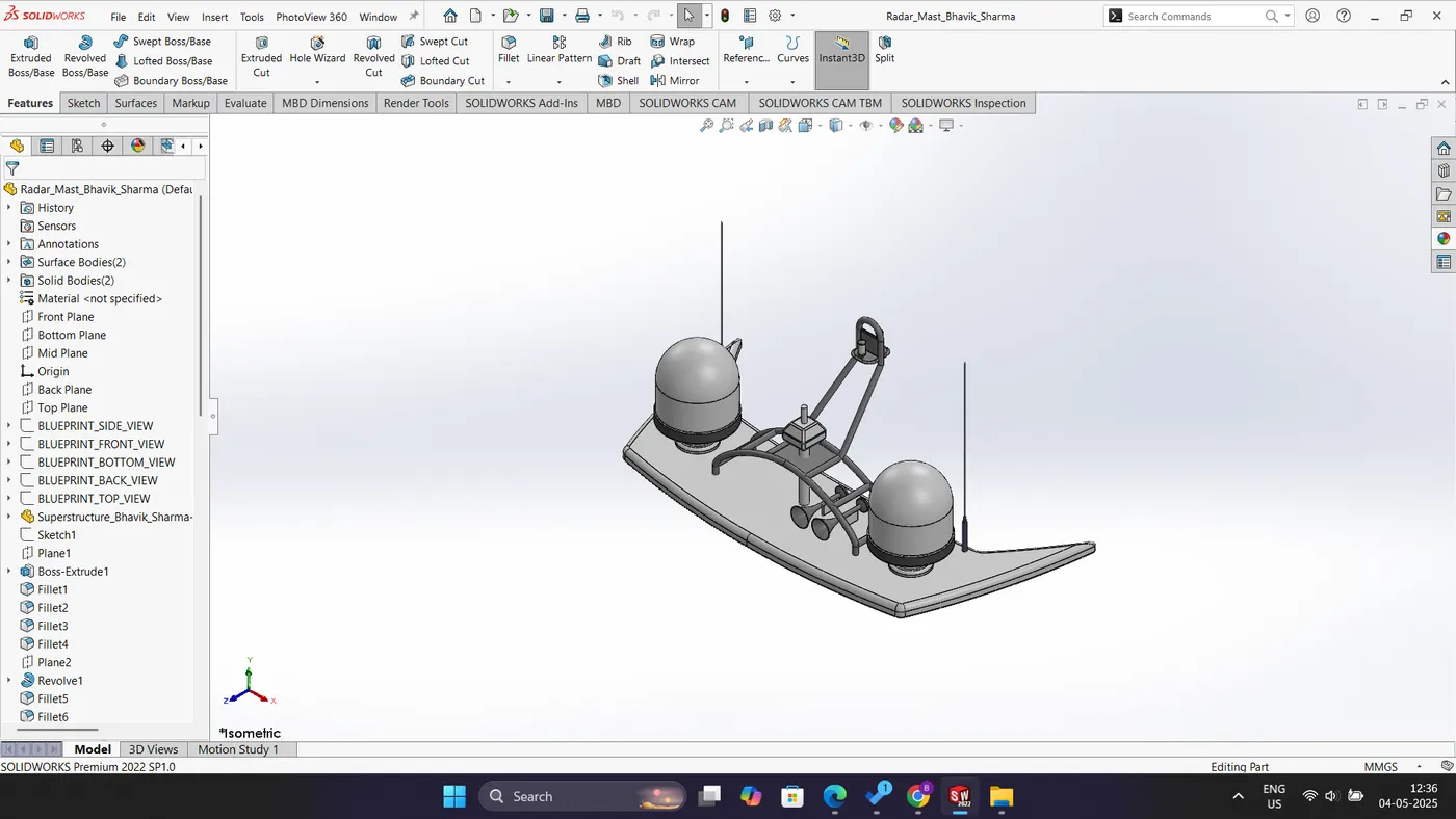
Fig: Isometric View
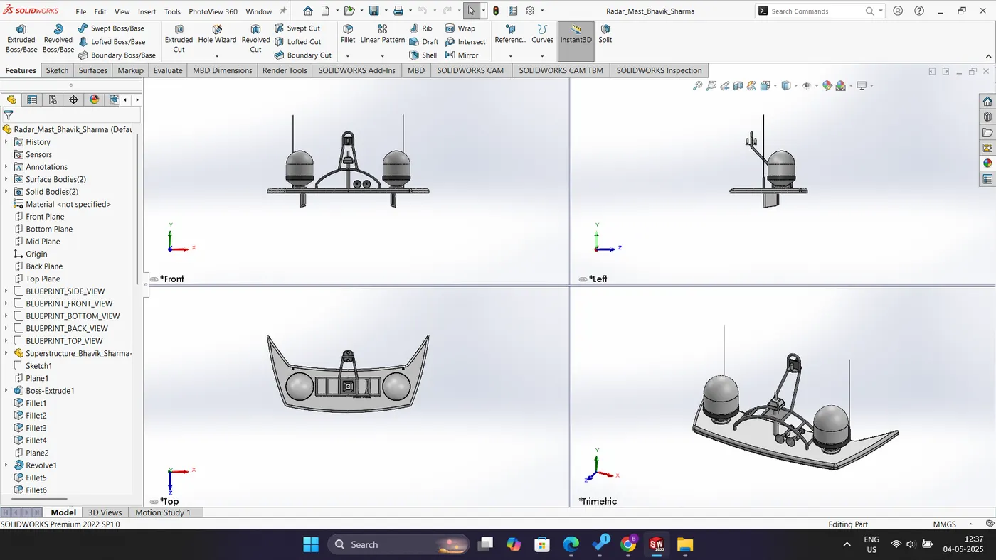
Fig: Multiple View
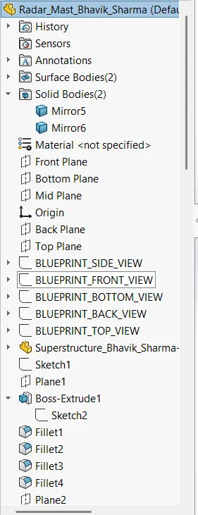
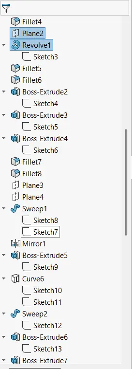
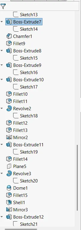
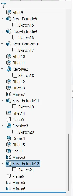
Fig: Feature Tree
Project Report on Sunseeker Yacht:
Title: Modelling of Sunseeker Predator Yacht
Objective: To develop a three-dimensional model of the Sunseeker Predator Yacht utilizing SolidWorks software.
Introduction: This document outlines the modeling of various components of the Sunseeker Predator yacht utilizing SolidWorks software. It will also detail the process of assembling these components and subsequently executing photo-realistic rendering of both the individual part files and the assembly files through the use of Photo View 360, thereby enhancing the aesthetic appeal of the yacht.
Design Methodology:
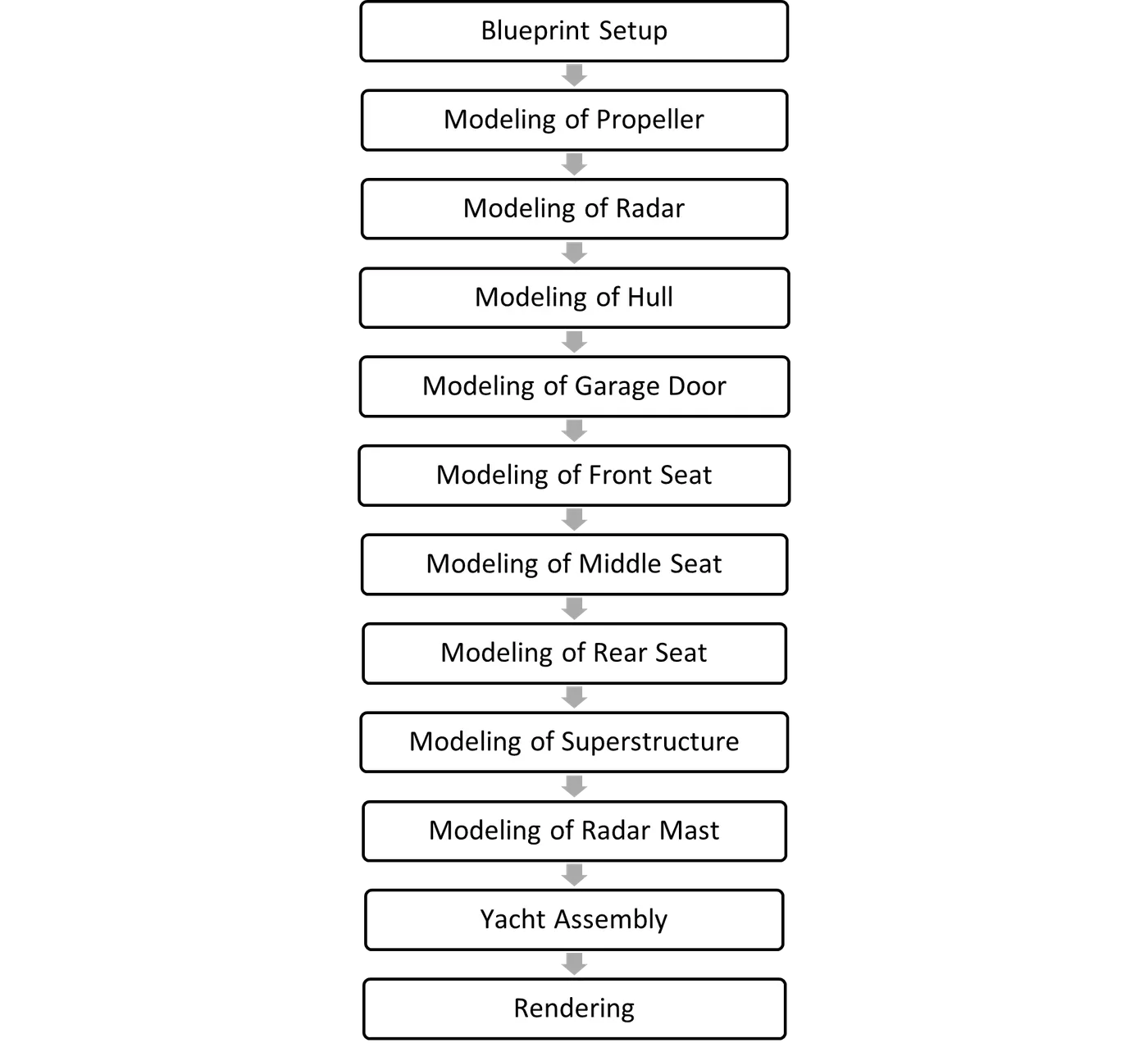
Description:
In this project, the following parts are designed,
- Blueprint Setup
- Propeller
- Radar
- Hull
- Garage door
- Front seat
- Middle seat
- Rear seat
- Superstructure
- Radar Mast
- Assembly
Blueprint Setup:
The initial step in initiating the model involves the utilization of blueprints. In this phase, all yacht blueprints are appropriately assigned to their corresponding planes. For instance, the blueprint depicting the front view of the yacht is positioned on the Front Plane, the side view is designated to the Mid Plane, the top view is allocated to the Top Plane, the back view is affixed to the Back Plane, and the bottom view is attached to the Bottom Plane. Two additional planes are manually generated using the reference geometry feature, designated as the Back Plane and the Top Plane. In this arrangement, the Top Plane has been renamed to the Bottom Plane, while the Right Plane is referred to as the Mid Plane.
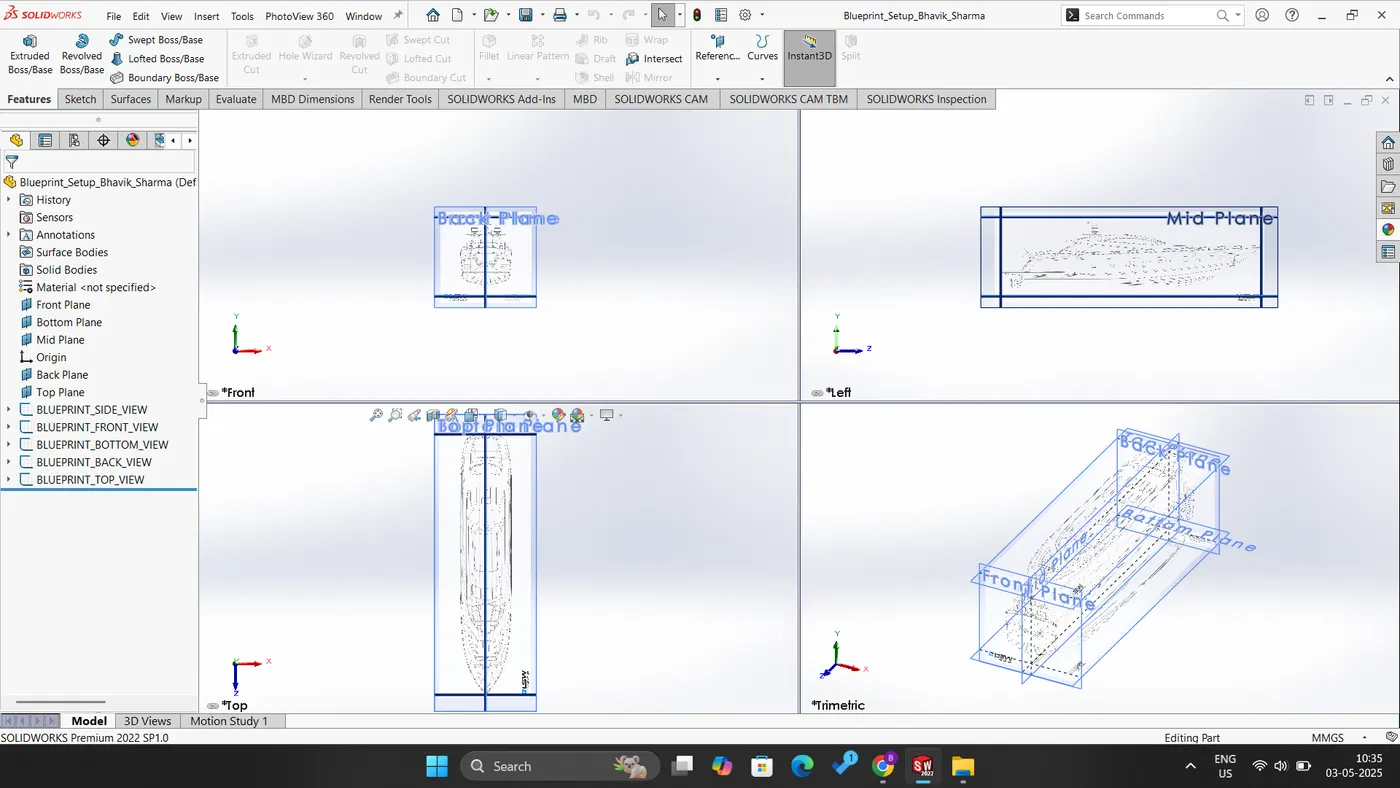
Fig: Blueprint Setup
Propeller:
The propeller is a rotary component of a yacht, securely attached to the rear section of the hull. In the modeling of the propeller, the following techniques are employed:
- Revolve: This feature is utilized to rotate a closed two-dimensional sketch around a central axis.
- Cut Extrude: This technique is used to remove material from the extruded component, specifically for creating an aperture in the revolved part.
- Loft: This method facilitates the creation of the blades of the propeller.
- Circular Pattern: This feature allows for the duplication of a specified pattern along a circular trajectory.
- Fillet: This technique is applied to provide rounded shapes to all corners of the design.
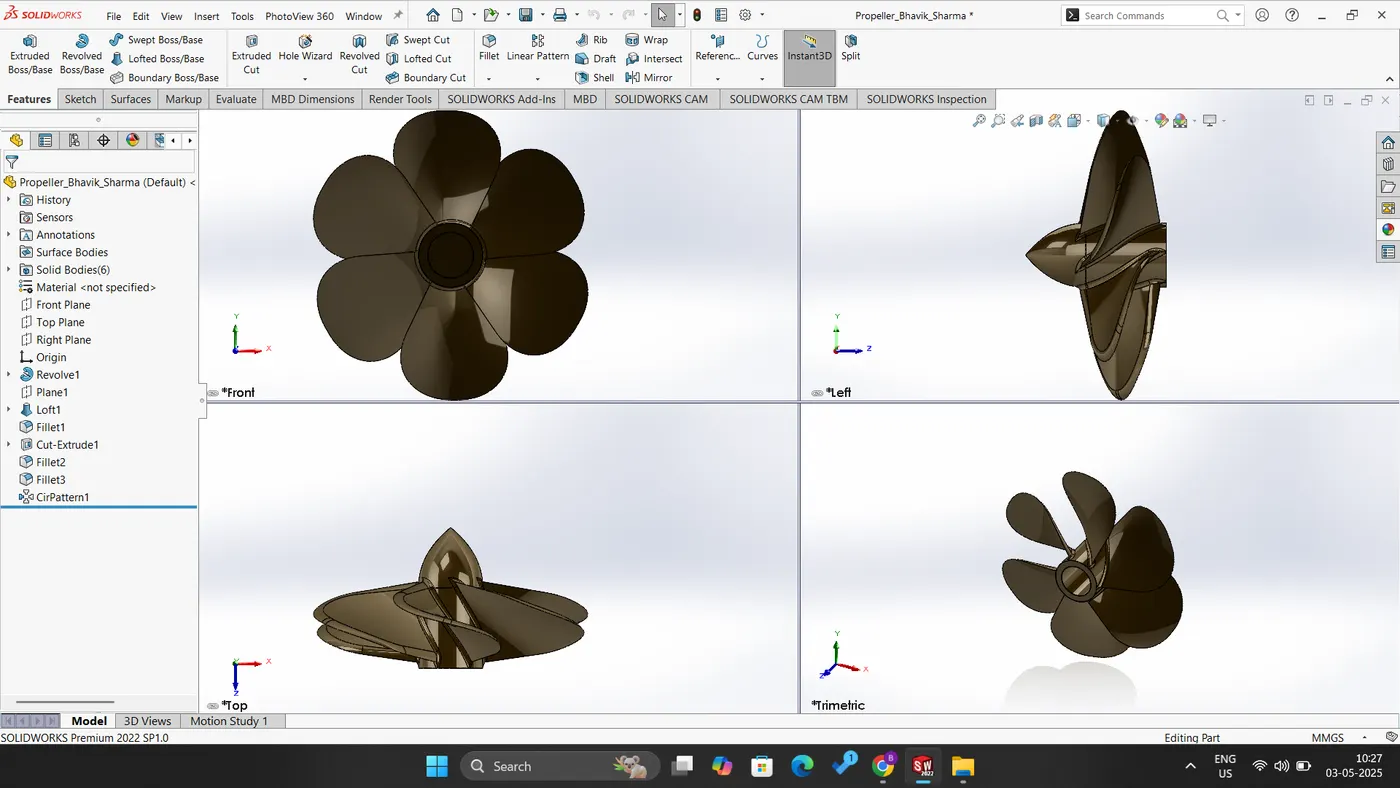
Fig: Propeller
Radar:
The radar component is a solid body that functions as a rotary element of the yacht. This component incorporates the following features:
- Boss Extrude: This feature is utilized to extrude a closed 2D sketch to a desired height.
- Cut Extrude: This function is employed to remove portions of the extruded component, allowing for the creation of holes or the elimination of undesired sections.
- Fillet: This feature is designed to create rounded shapes at corners and edges with a specified radius.
- Sketch Pattern: This function is used to replicate features across a defined sketch point.
- Mirror: This utility enables the mirroring of the body, using a designated reference face.
- Split Line: This feature facilitates the division of a face into segments; within the radar component, it is specifically employed to apply text onto the surface.
- Text: A three-dimensional text is to be applied to the radar using the Split Line command, ensuring accurate representation and placement.
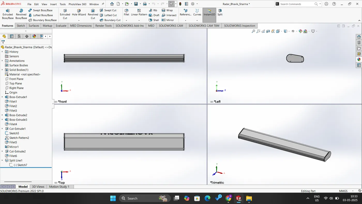
Fig: Radar
Hull:
The hull constitutes the foundational component of a yacht, incorporating various surface features that facilitate the design of its intricate shapes. By utilizing the merge and knit options, the entire surface component can be transformed into a solid structure. The following surface commands are employed in the development of this part:
- Blueprint Setup: This function serves as the groundwork for sketching curves and outlines necessary for surface creation.
- Surface Loft: This command is used to generate a surface by employing a minimum of two profile curves in conjunction with two guide curves.
- Curve: This element acts as either a profile or guide curve to form the surface, created from two two-dimensional sketches placed on different planes.
- Surface Trim: This tool is utilized to trim the surface as required.
- Surface Extrude: This command is applied to extrude the surface.
- Surface Knit: This option is employed to combine two or more surfaces.
- Surface Fill: This command creates a surface utilizing four boundary curves.
- Shell: This function hollows the solid model while maintaining a specified thickness.
- Boss Extrude: This tool generates a solid body from a two-dimensional sketch.
- Cut Extrude: This command is used to create cuts in the extruded part, enabling the formation of holes or the removal of undesirable sections.
- Fillet This feature is applied to provide rounded shapes to corners and edges.
- Chamfer: This command is utilized to create a taper along corners and edges.
- Linear Pattern: This tool allows for the creation of a pattern along a linear path.
- Dome: This function generates a dome shape over a solid part.
- Split: This command is employed to excise a solid section from the body.
- Surface Offset: This tool is used to create an offset of the surface.
- Delete Face: This command eliminates the designated face from the model.
- Sweep: This function forms helical shapes and pipes by utilizing a profile sketch along a guide curve to define the desired path.
- Revolve: This command revolves a closed sketch around an axis, with one of the lines serving as the axis of revolution.
- Mirror: This tool mirrors half of the hull to create a completely solid body.
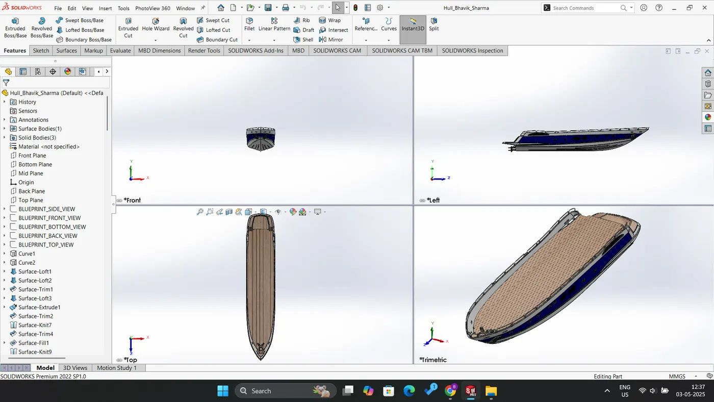
Fig: Hull
Garage door:
The text pertains to a section of a hull that serves as the foundation for a garage door. The garage door comprises several essential solid features:
- Cut Extrude: Employed to sever the designated portion of the hull.
- Shell: Utilized to create a hollow structure within the solid body, maintaining a specific thickness.
- Fillet: Applied to round the corners and edges, enhancing the overall design.
- Mirror: Implemented to replicate one half of the hull, ensuring symmetry in the structure.
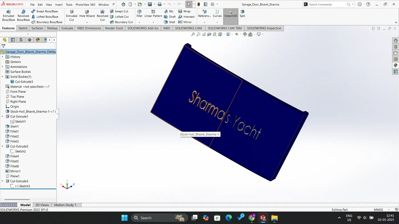
Fig: Garage Door
Front seat:
The front seat of the yacht
- Surface Loft: This technique is employed to create a surface utilizing a minimum of two profile curves and two guide curves.
- Surface Knit: This method enables the knitting of two or more surfaces together.
- Surface Sweep: This process facilitates the sweeping of a surface along a specified path.
- Surface Trim: This function is utilized to refine or trim the surface as required.
- Surface Fill: This technique is used to fill a surface defined by four boundary curves.
- Cut Extrude: This function is utilized to remove material from the extruded section, thereby allowing for the creation of holes or the elimination of unwanted portions.
- Fillet and Edges: This feature serves to round the corners of a component.
- Chamfer: This operation is applied to create a taper at the corners and edges of a part.
- Mirror: This utility is used to replicate one-half of the front seat to its corresponding side.
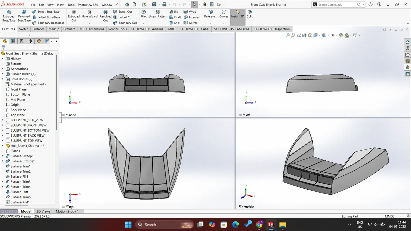
Fig: Front Seat
Middle seat:
In the middle seat section, the offset surface of the hull serves as the primary reference base. This section comprises the following features:
- Boss Extrude: This feature is employed to generate a solid body from a two-dimensional sketch.
- Chamfer: This is utilized to create a tapered shape for the corners and edges.
- Fillet: This feature is designed to provide a rounded shape to the corners and edges.
- Cut Extrude: This is used to remove material from the extruded component.
- Mirror: This function is applied to replicate the half portion of the middle seat to the opposing side.
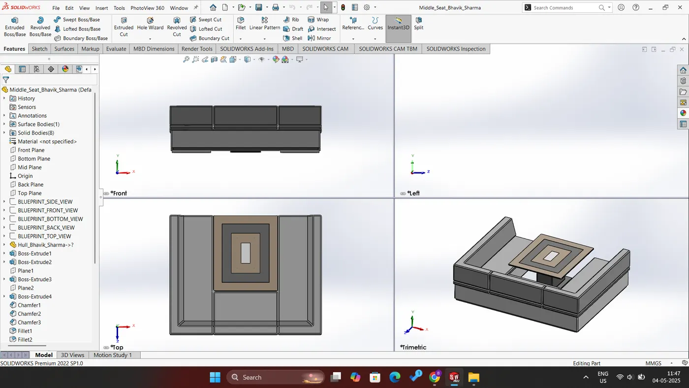
Fig: Middle Seat
Rear seat:
In the rear seat section, the offset surface of the hull serves as a fundamental reference. This section comprises the following features:
- Surface Sweep: Utilized to create a swept surface.
- Surface Offset: Employed to generate an offset version of the surface.
- Surface Trim: Implemented to trim the surface accordingly.
- Ruled Surface: Designed to extend the surface at an angle using either a curve or a line.
- Surface Knit: Applied to combine two or more surfaces together.
- Surface Extrude: Utilized to extrude the surface into three dimensions.
- Surface Extend: Used to extend the existing surface.
- Surface Loft: Created by utilizing a minimum of two profile curves and two guide curves to develop a surface.
- Boss Extrude: Employed to transform a two-dimensional sketch into a solid body.
- Sweep: Used to develop helical shapes and pipes along a path defined by a profile sketch and a guide curve.
- Revolve: Facilitates the revolution of a closed sketch around an axis, with one of the lines designated as the axis.
- Fillet: Applied to round off corners and edges.
- Chamfer: Used to create beveled corners and edges.
- Mirror: Utilized to reflect half of the rear seat design onto the opposite side.
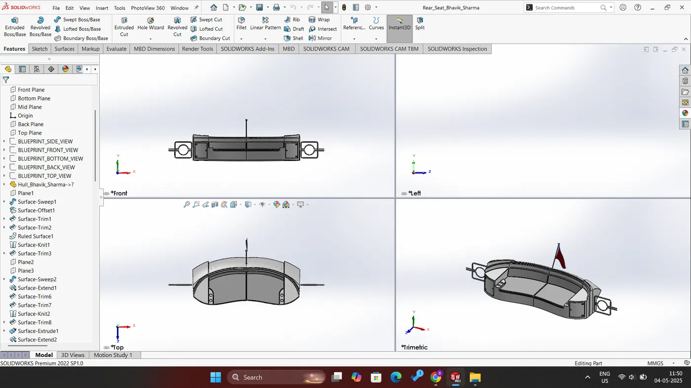
Fig: Rear Seat
Superstructure:
In the design of the superstructure, the offset surface of the hull serves as a foundational reference, while a blueprint setup is utilized to outline sketches on the designated planes. This process encompasses several essential features:
- Surface Extrude: This feature is employed to extend the surface.
- Surface Sweep: This technique is utilized to create a swept surface.
- Curve: Curves serve as profile or guide curves to generate surfaces and are produced using two distinct 2D sketches drawn in separate planes.
- 3D Sketch: This allows for three-dimensional sketching, facilitating the connection of endpoints of curves.
- Surface Trim: This function is used to trim surfaces utilizing either surface or sketch entities as trimming tools.
- Surface Knit: This feature combines individual surfaces into a unified entity.
- Ruled Surface: This is employed to extend a surface at an angle using a curve or line.
- Surface Loft: This method creates a surface using two guide curves and two profile curves.
- Surface Extend: This feature is utilized to prolong the surface.
- Surface Offset: This function enables the offsetting of a surface from its base.
- Split Line: This is used to divide a face using a sketch entity.
- Delete Face: This feature allows for the removal of a face.
- Boss Extrude: This technique is employed to extrude a closed sketch.
- Cut Extrude: This function is utilized to create holes or remove unwanted sections by cutting an extruded part.
- Fillet: This feature provides rounded shapes to corners and edges.
- Chamfer: This is used to create tapered shapes on corners and edges.
- Mirror: This capability allows for mirroring half of the superstructure to its opposite side utilizing a mid-plane as a reference mirror face.
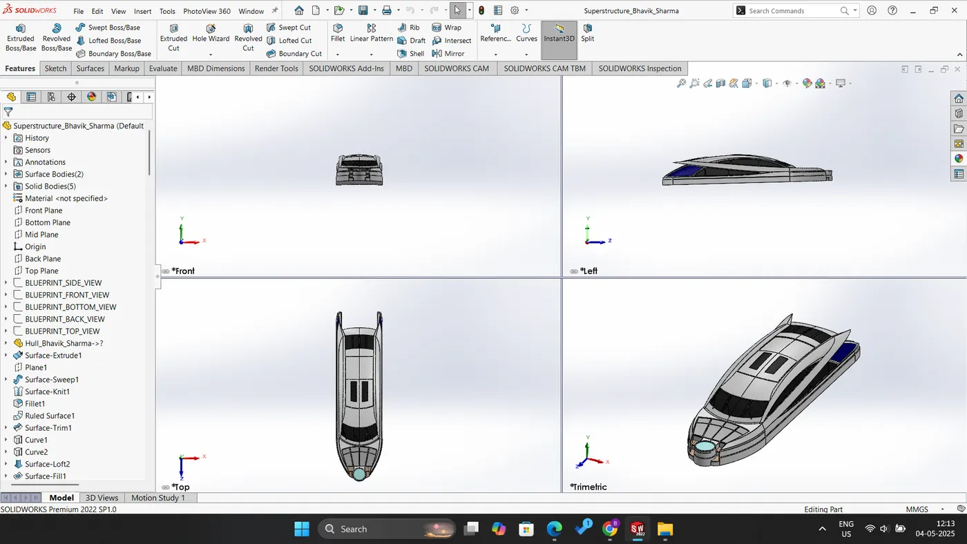
Fig: Superstructure
Radar Mast:
The radar mast is an integral component that is positioned atop the superstructure. The surface offset from the back upper window of the superstructure serves as the base reference for the radar mast. This component incorporates the following features:
- Boss Extrude: Employed to extrude a closed sketch.
- Revolve: Utilized to revolve a closed sketch around an axis by designating one of the lines as the axis.
- Sweep: Applied to sweep a profile curve along a specified path.
- Curve: Functions as either a profile or guide curve to generate surfaces, created using two distinct two-dimensional sketches located in different planes.
- Fillet: Used to round off corners and edges.
- Chamfer: Provides a taper to corners and edges.
- Shell: Designed to create a hollow body.
- Combine: Used to merge two solid bodies.
- Mirror: Facilitates the mirroring of half of the superstructure to its opposite side by utilizing a mid-plane as the mirror face.
Fig: Radar Mast
Assembly:
The assembly of all the components previously discussed is achieved through the utilization of various mating techniques. These mating strategies effectively provide the components with constrained motion by their intended functionality. The specific mates employed in this assembly to integrate all the parts are as follows:
- Coincident Mate: This mate facilitates a constrained reciprocating motion for the component.
- Concentric Mate: This mate is utilized to align the components in a singular direction.
- Angle Mate: This mate allows for rotary motion of the components about a specified axis or plane.
- Hinge Mate: This mate is employed to simulate the hinge mechanism in the garage door component.
- Tangent Mate: This mate provides constrained motion to the radar assembly.
- Each of these mates plays a critical role in ensuring the proper functioning of the overall assembly.
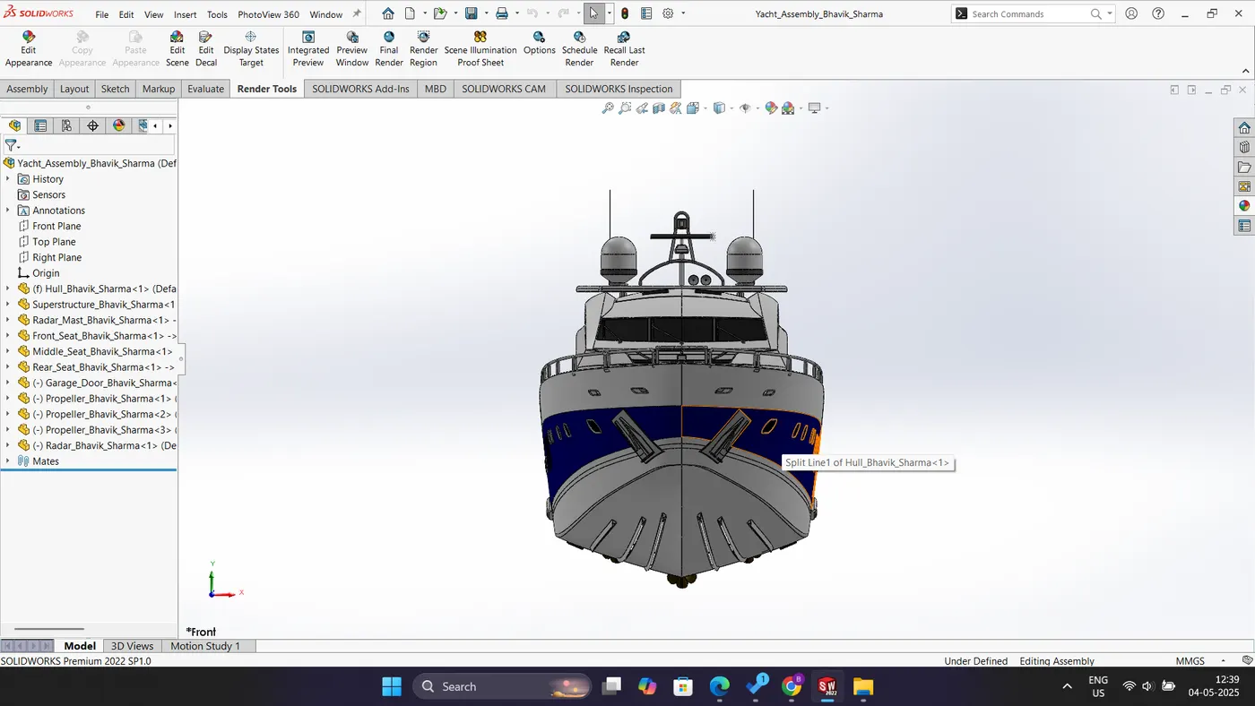
Fig: Front View of Yacht Assembly
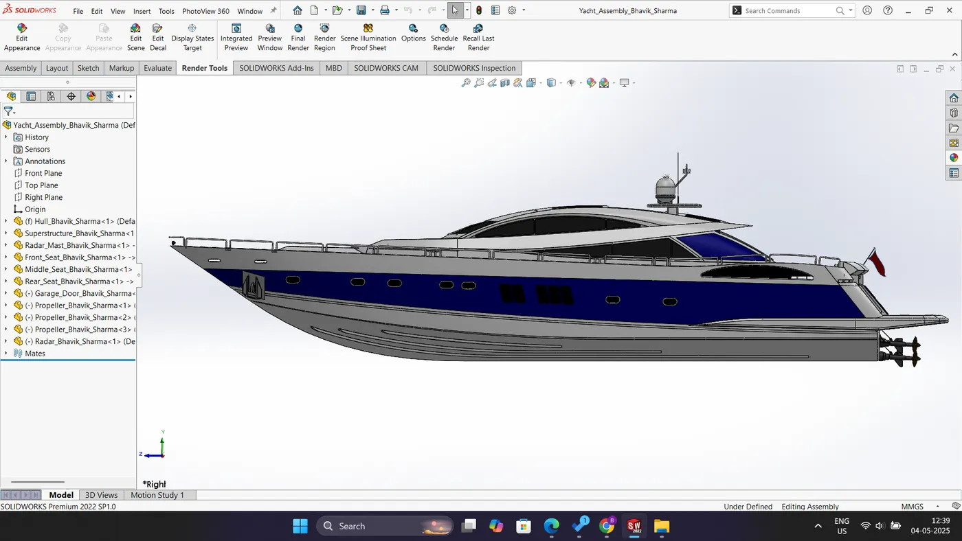
Fig: Side View of Yacht Assembly
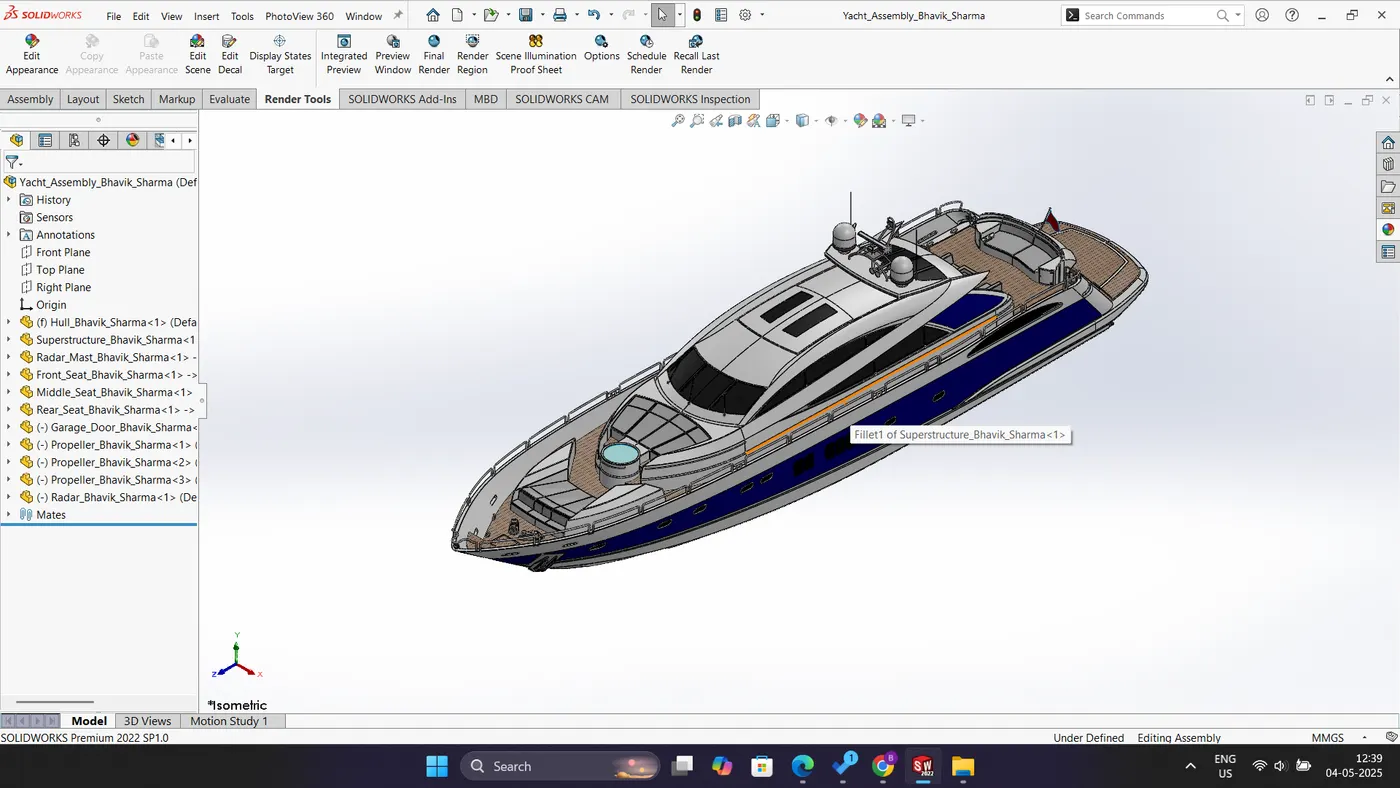
Fig: Isometric View of Yacht Assembly
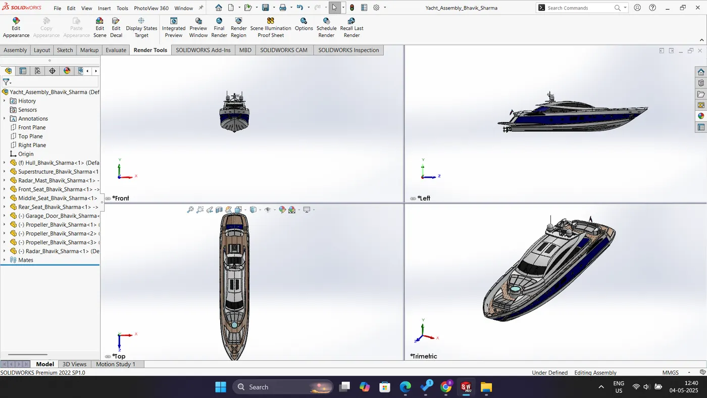
Fig: Multiple View of Yacht Assembly
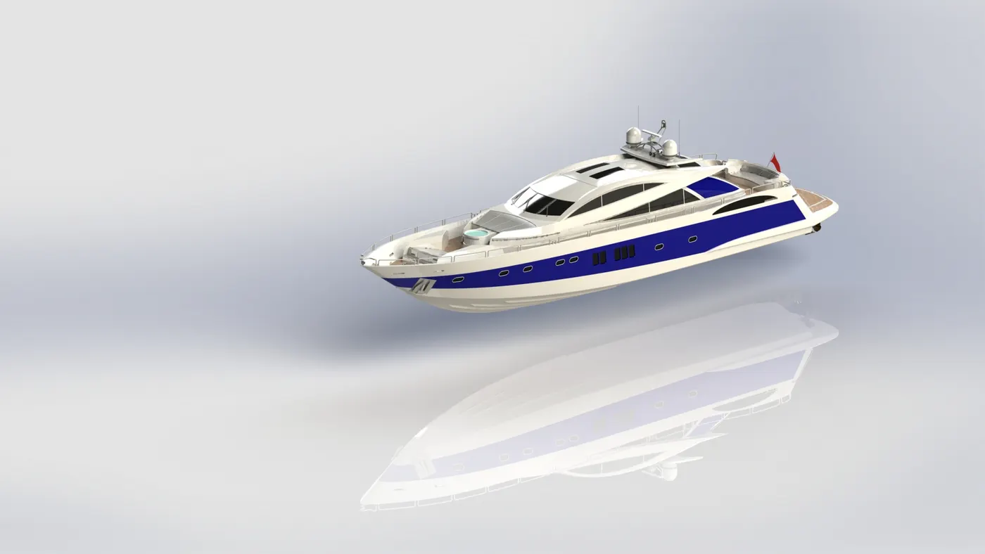
Fig: Rendered image of Yacht Assembly
Conclusion: The modeling, assembly, and photorealistic rendering of the Sunseeker Predator yacht have been accomplished using SolidWorks.
As the file size is quite big, so I have attached link below;