Radar Mast & Final Assembly of Yacht
FINAL ASSEMBLY OF YACHT
1. OBJECTIVE
To use SolidWorks to create a realistic and fully integrated yacht model by designing and assembling every component of the yacht, including the radar mast, hull, garage door, seating, superstructure, propeller, and radar system.
2. INTRODUCTION
In this project, separate yacht components will be designed and put together to create an accurate and useful model. The model was developed using SolidWorks and a variety of advanced CAD tools and rendering procedures. All of the parts are flawlessly integrated in the finished assembly. Solidworks Photoview 360 or Solidworks Visualize are used to render the 3D model.
3.DESIGN METHODOLOGY
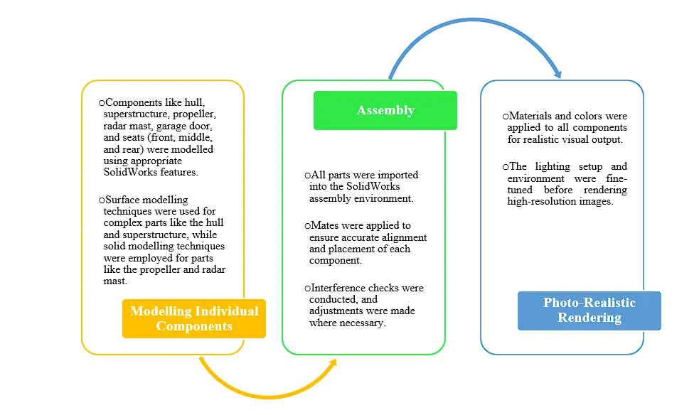
The assembly process involved the following steps,
i. Individual Component Modelling
SURFACE BODIES (Hull, Superstructure, Front and Rear Seat)
- Establishing the blueprint.
- Creating constraint sketches based on blueprint references.
- Projected curve formation.
- Surface loft is used to form surfaces from these projected curves.
- Surface extrude, surface fill, surface sweep, and ruled surfaces are some of the features that are used to form other surfaces.
- In order to create a solid body from surfaces, we knit the surfaces together until there are no gaps between them.
FOR SOLID BODIES (Radar mast, garage door, middle seat, and propeller)
- We have utilized the blueprint as a guide for a few solid bodies.
- Constrained drawing creation.
- Utilizing features such as Swept Loft, Cut Extrude, and Boss Extrude.
ii. Assembly
- Using the appropriate mates, all the components are put together in SolidWorks assembly environment.
- Verify whether there is any interference between the components.
- If interference arises, adjust the components appropriately to prevent inter-part interference.
iii. Photo-Realistic Rendering
- The yacht's setup and adjustment to our surroundings.
- Modifying altering materials and colours.
- Decals are added.
- Setting up the rendering scene.
- The configuration of rendering lights.
- The final rendering.
The flowchart below illustrates the design and assembly workflow:
4. DESCRIPTION
4.1. Blueprint Setup
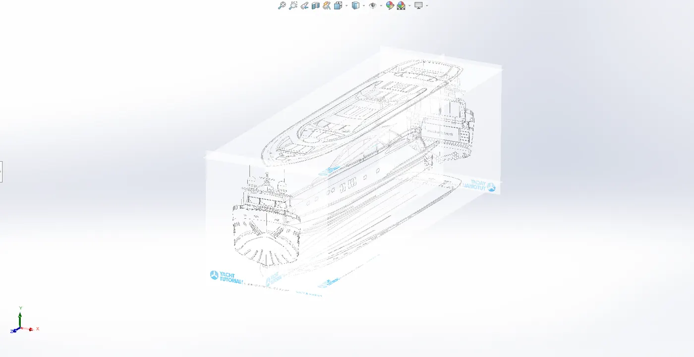
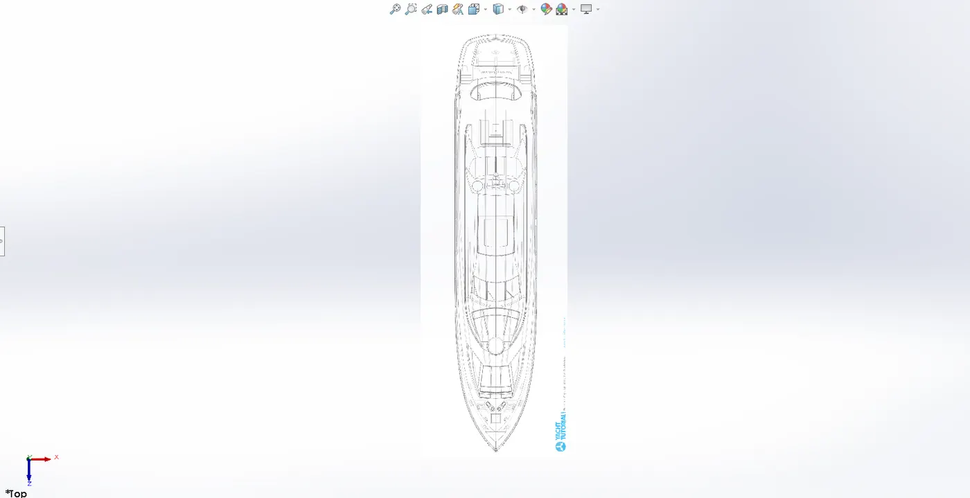
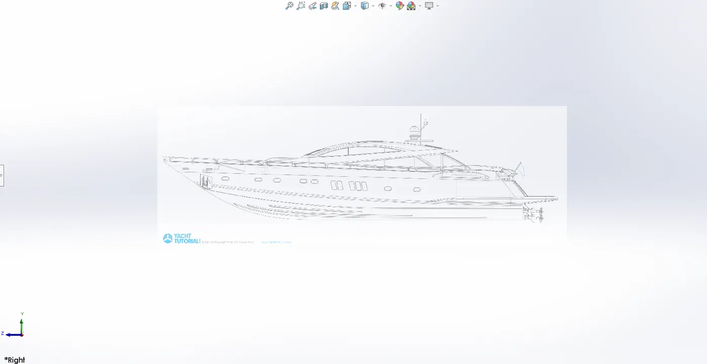
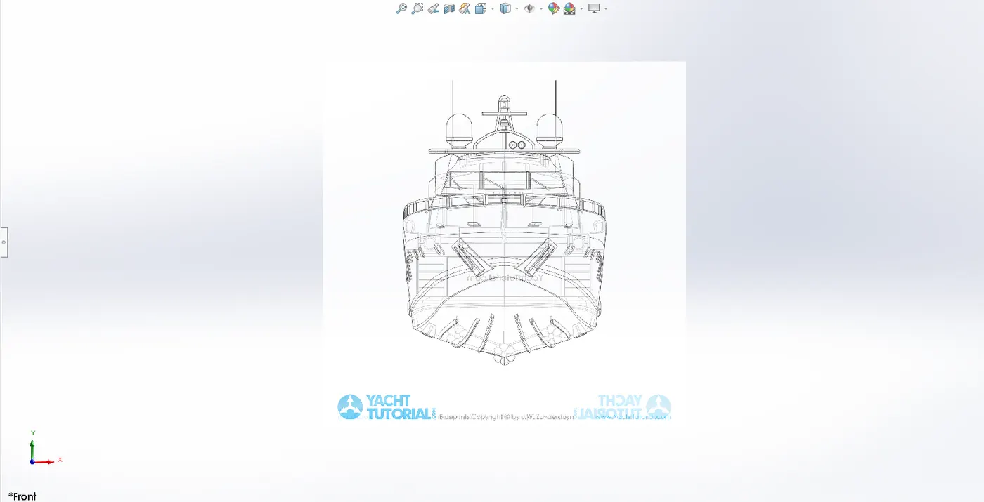
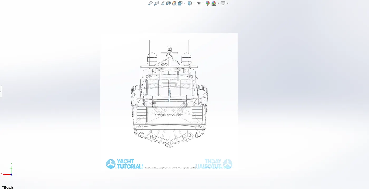
Creating a comprehensive digital layout of the complete yacht is part of the blueprint setup process. This stage guarantees that every part—including the radar and propeller—is appropriately incorporated into the overall design of the boat. With its technical drawings, measurements, and assembly instructions, it acts as the main manual for assembling the yacht.
A high-level plan that directs team members through the process of creating and adding to an open course is called a design blueprint. Its goal is to provide a visual representation of the course's overarching "architecture" that will direct the process of collaboration, design, and development.
We need some sort of reference in order to design and model the yacht. The intended views of the product from all angles (front, side, top, bottom, and back) or some idea sketches could serve as that reference. In the Solidworks environment, we created blueprints of the desired views of a yacht and positioned each view in relation to the others. After that, we designed every component or body of the yacht using this blueprint setup as a guide. We set it up correctly and insert the blueprint views as a sketch.
4.2. Propeller
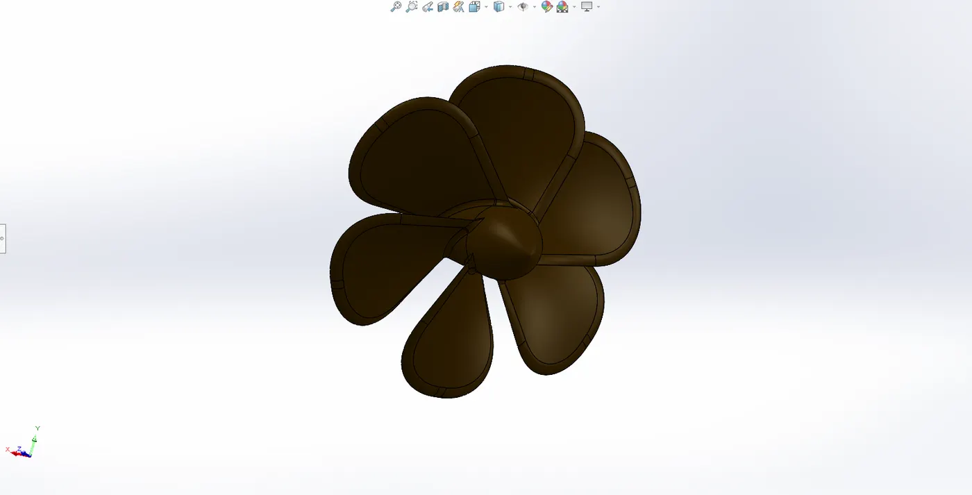
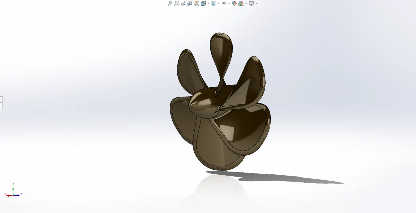
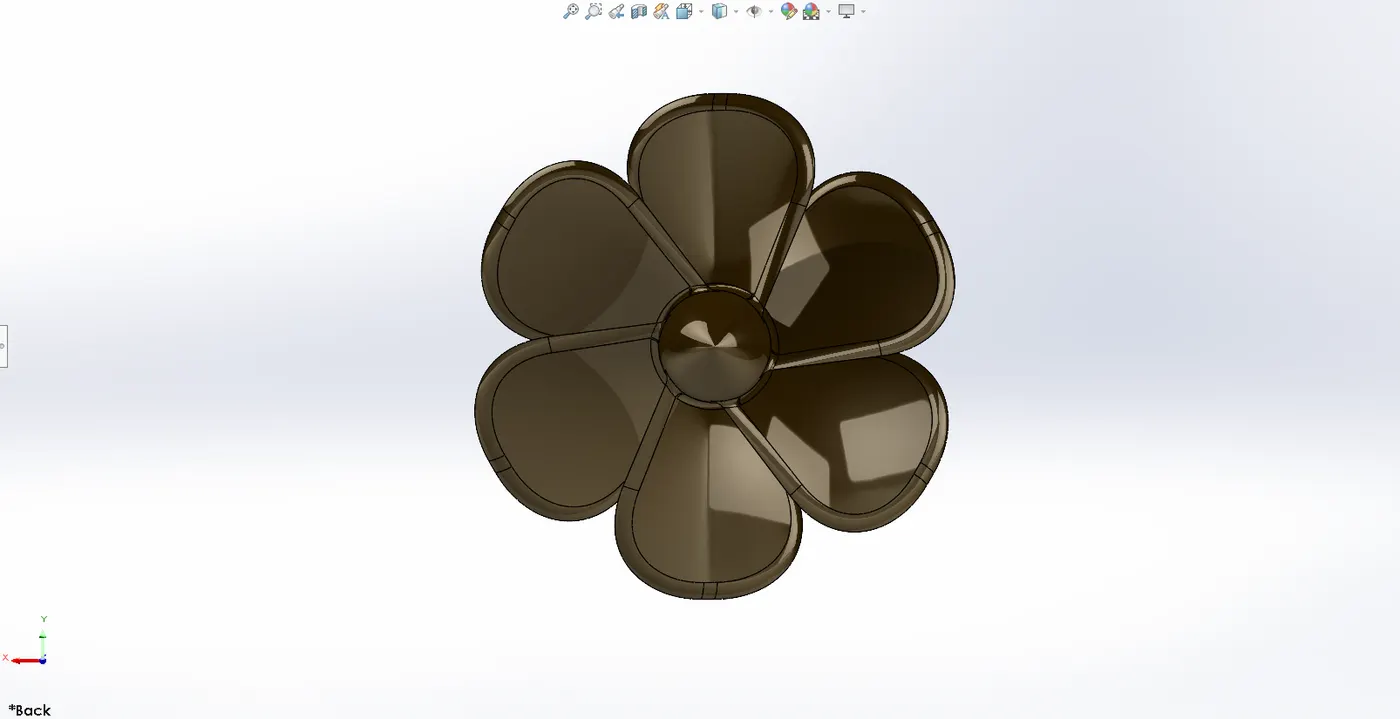
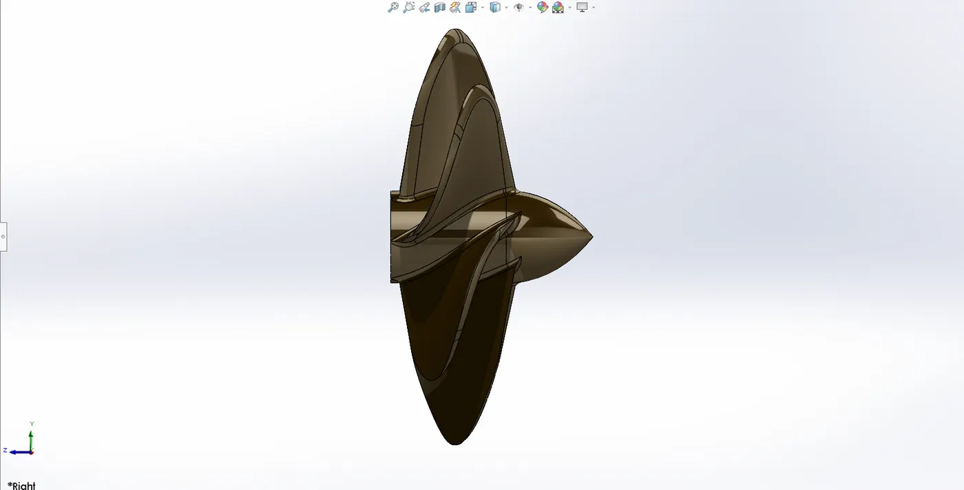
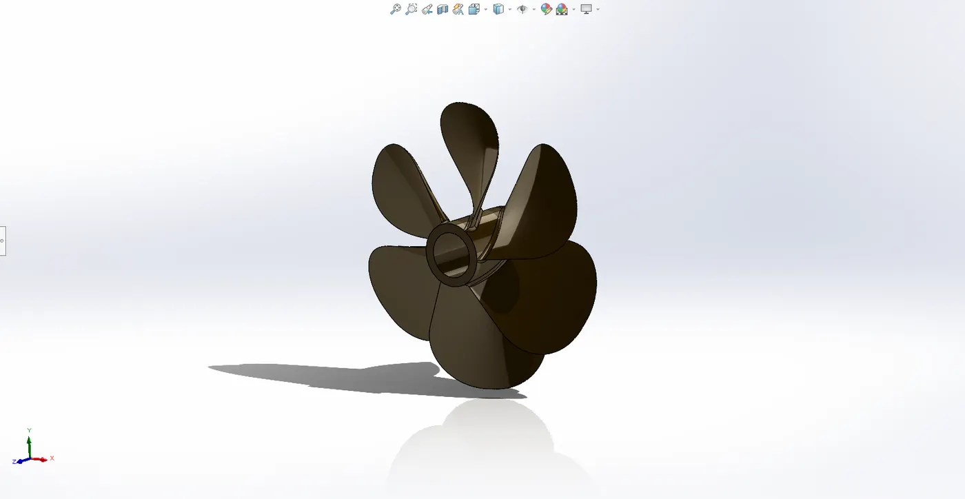
An essential part of the yacht's propulsion system is the propeller. It must be built to be as efficient as possible on the water, guaranteeing maximum speed, fuel economy, and manoeuvrability.
4.2.1. Design Overview
A propeller is a machine that functions similarly to Archimedes' screw when rotated. It has a revolving hub and radiating blades arranged at a pitch to create a helical spiral. It acts on a working fluid, such air or water, to convert rotational power into linear thrust
4.2.2. CAD Modelling Process
The yacht's propeller is a rotating component attached to the rear of the hull. I used the following features in the propeller.
- Rotate: This function rotates the closed two-dimensional sketch around a central axis.
- Cut extrude: It is employed to cut the portion that has been extruded.
- Revolve: This function is utilized in this section to create a hole over the revolved portion.
- Loft: It's utilized to make the propeller's vanes.
- Pattern: The circular pattern is used to replicate the pattern in a circle.
- Fillet: It is used to give all of the corners a rounded appearance.
4.3. Radar
Without radar equipment, yacht would not be able to spot many of the floating objects in the water. Yacht's radar equipment will notify of other objects in the water that may not be aware of. Yacht can avoid running over a sandbar or reef by using this approach.
4.3.1. Design Overview
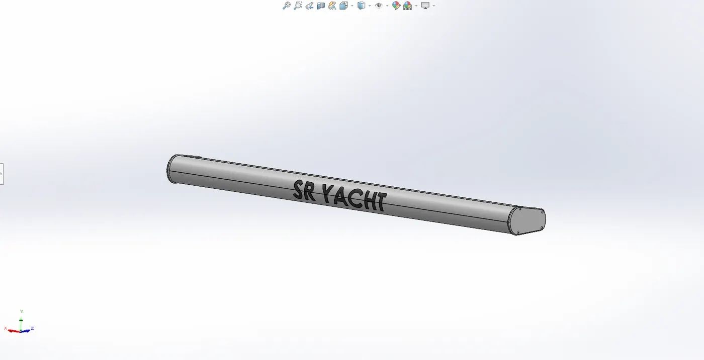
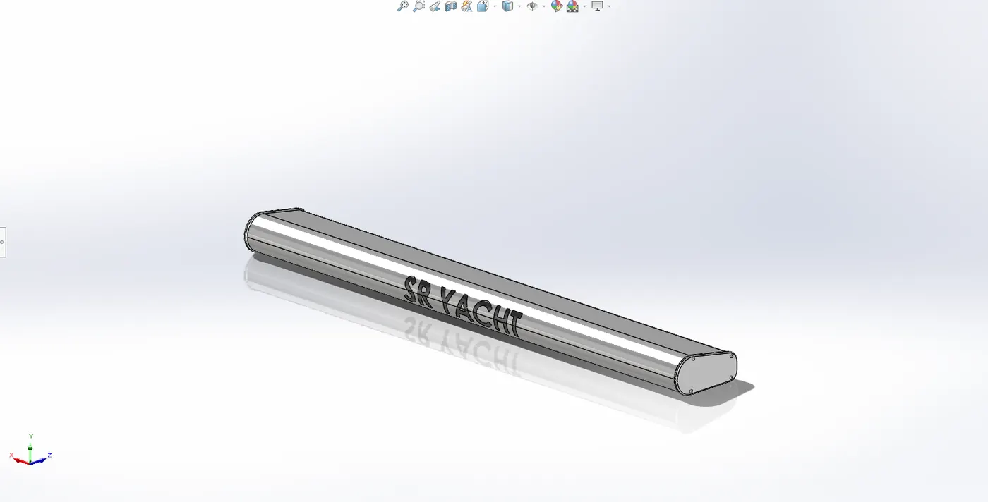
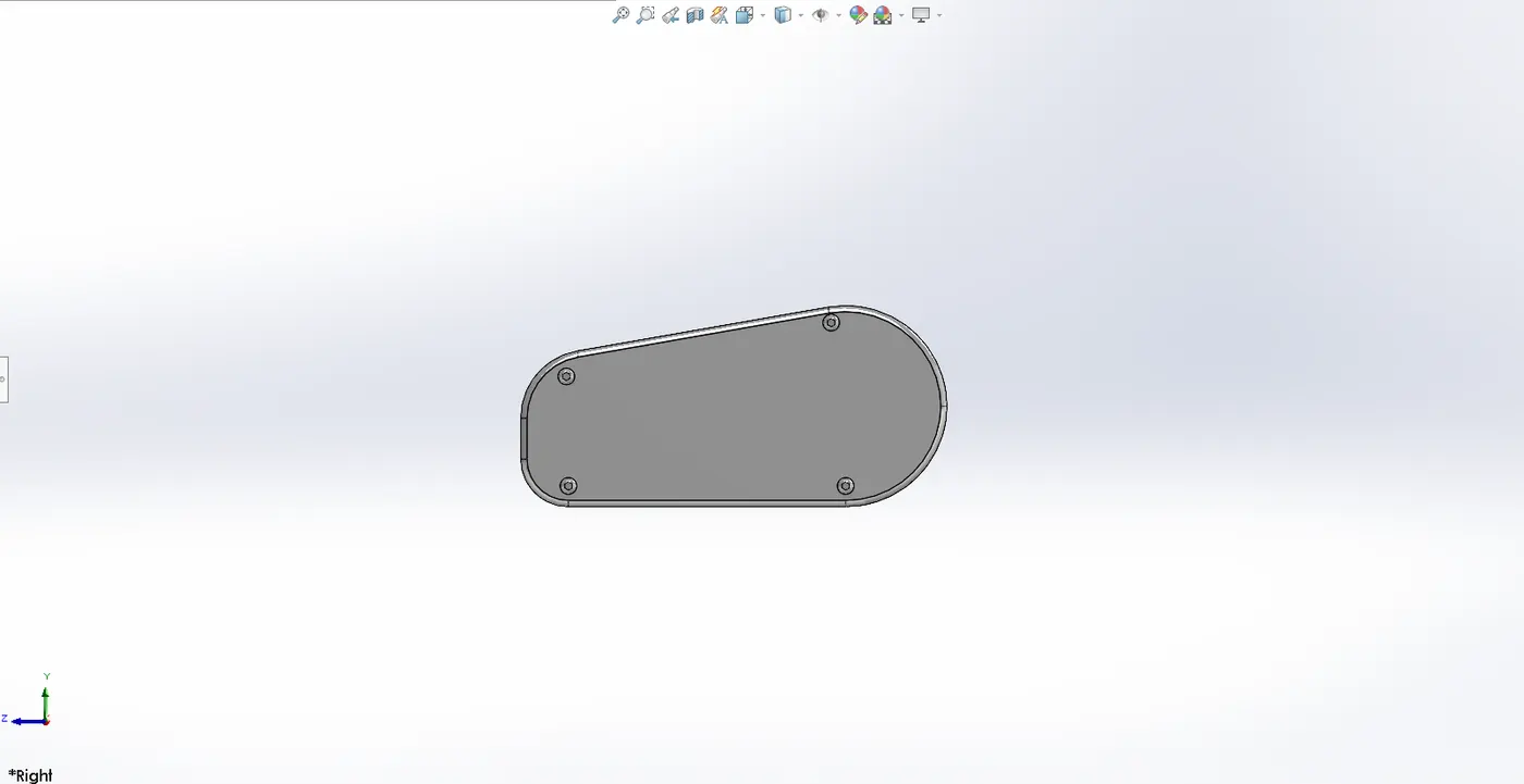
Navigation, collision avoidance, and weather monitoring all depend on the radar system. The radar system is represented in the yacht's CAD design as a mix of the housing, mounting structure. The goal is to make sure the radar unit fits correctly into the yacht's construction.
4.3.2. CAD Modelling Process
- Extrude the closed 2D sketch to the desired height using the boss extrude tool.
- Cut extrude: It is employed to cut the portion that has been extruded.
- Fillet: It is used to give all of the corners a rounded appearance.
- The purpose of a sketch pattern is to pattern features at a sketched spot.
- Mirror: By using the mirror face as a reference, it is used to mirror the body.
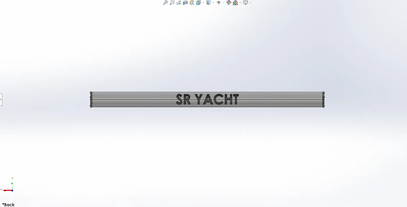
- The purpose of the spittle line is to cut the face into pieces. This capability allows the text to be printed over radar.
- Text: Using the split line command, this 3D text will be written across the radar.
4.4. Hull
Marine boats hulls serve as its structural core and are in charge of buoyancy, stability, and hydrodynamic performance. To maximize watercraft efficiency, the design strikes a compromise between strength, weight, and fluid dynamics.
4.4.1. Design Overview
The watertight body of a boat or ship is called a hull. The hull may have a deck covering it entirely or in part, or it may open at the top. A deckhouse and additional superstructures like a funnel, derrick, or mast may be located at the top of the deck.
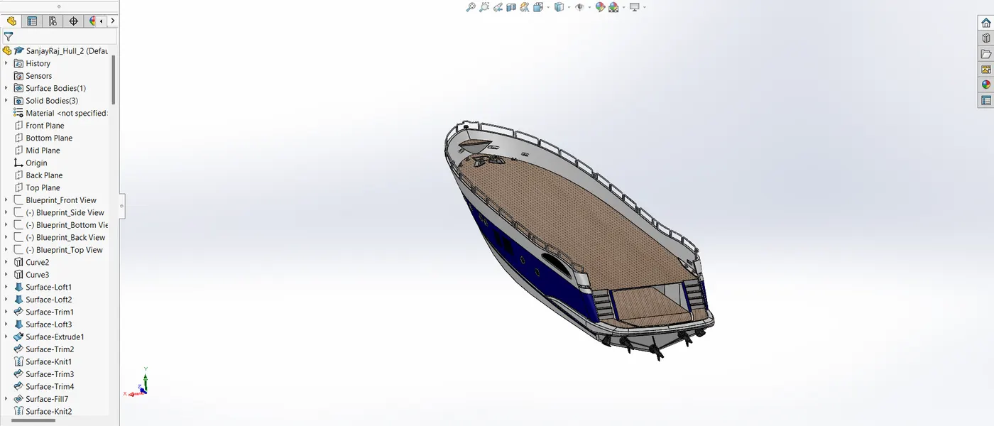
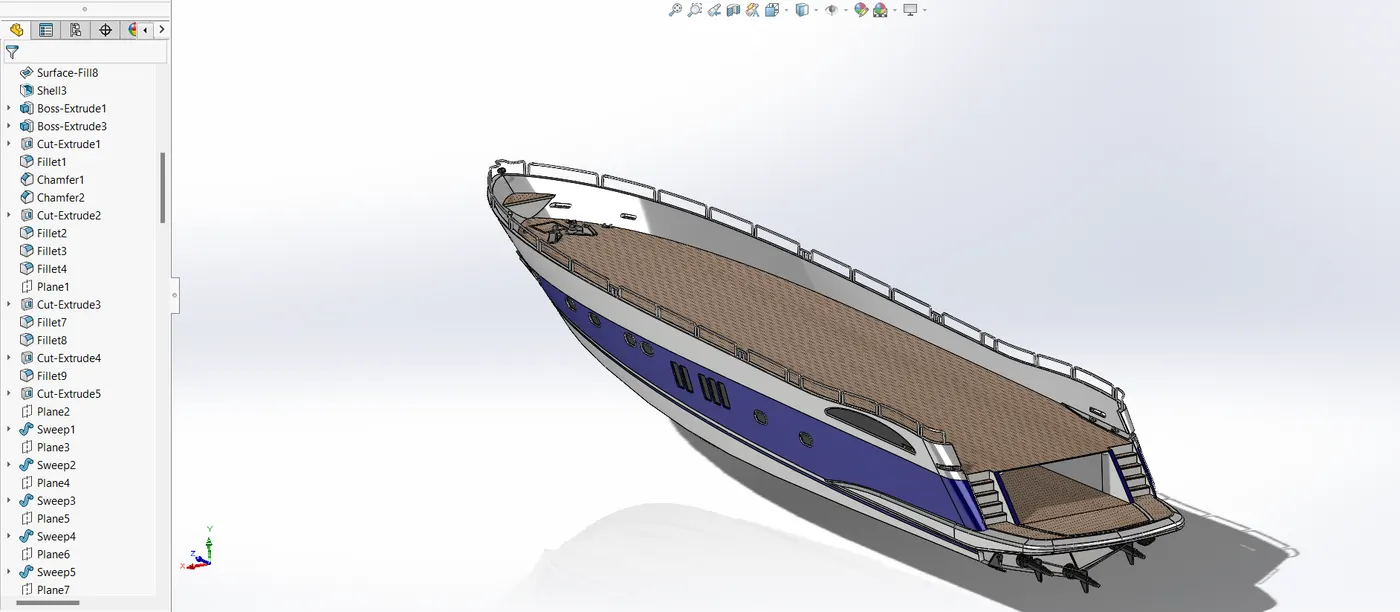
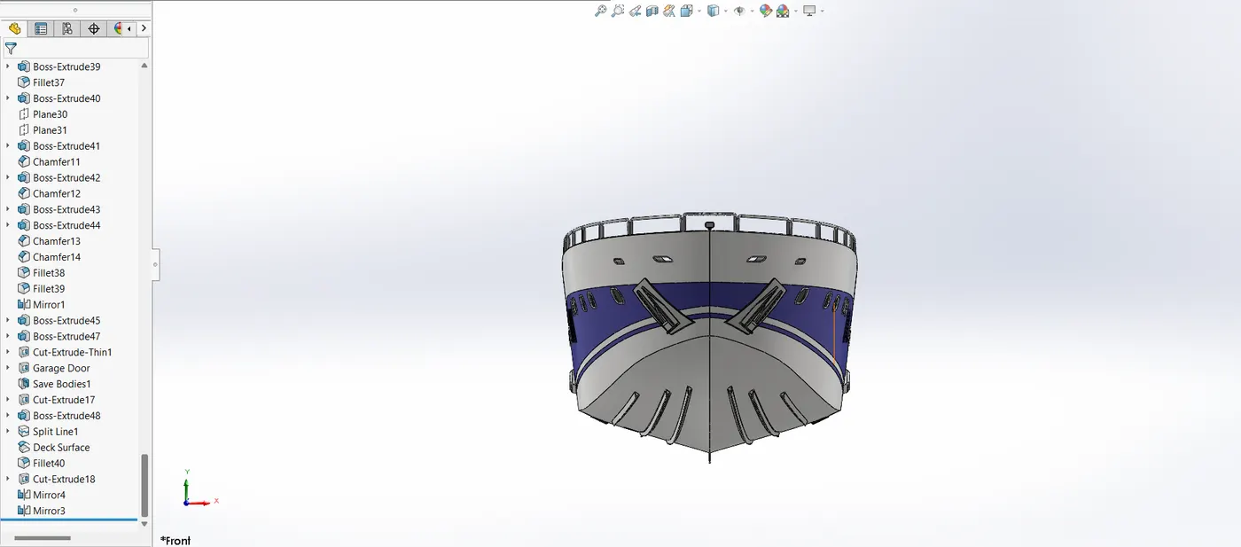
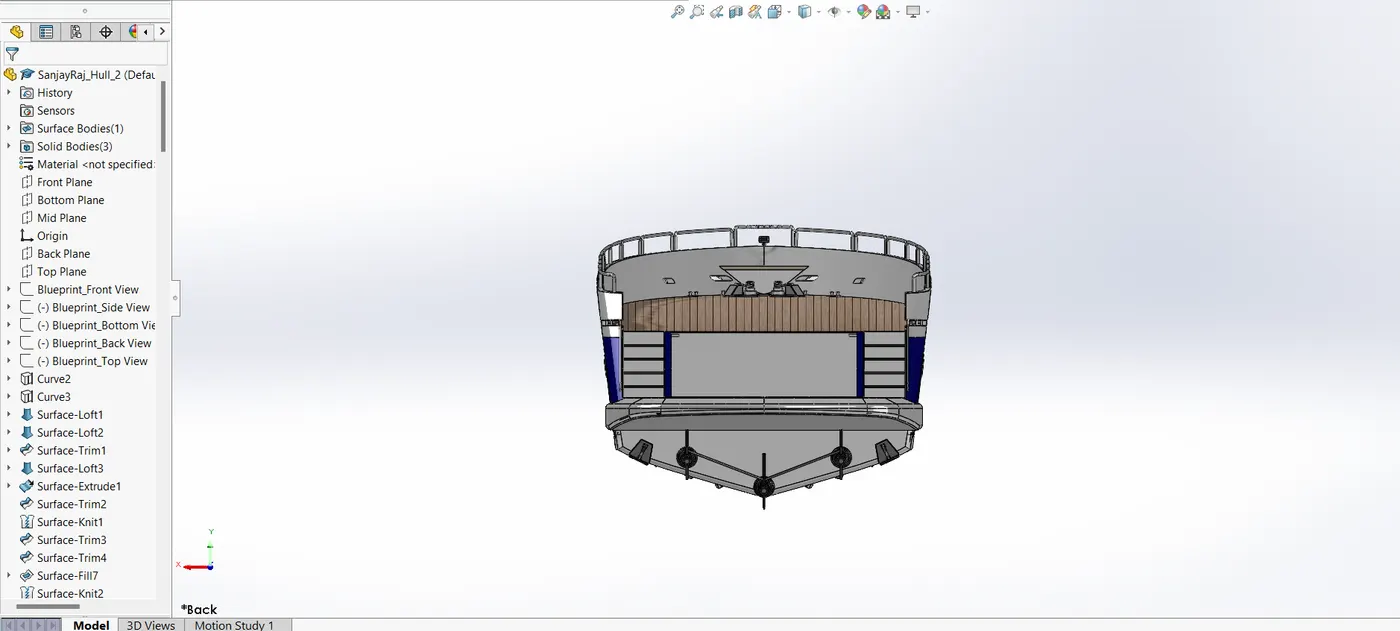
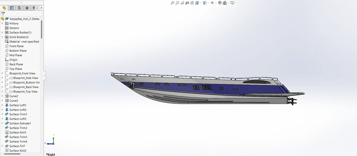
The base of a yacht is called the hull. Its many surface characteristics aid in the construction of this part's intricate shapes. The entire surface portion was then turned into a solid using the merge and knitted option.
4.4.2. CAD Modelling Process
The base of a yacht is called the hull. Its many surface characteristics aid in the construction of this part's intricate shapes. The entire surface portion was then turned into a solid using the merge and knitted option. The hull model was created using surface and solid modelling techniques. Key steps included:
- The blueprint setup serves as a foundation for drawing the surface's outlines and curves.
- Surface loft: this technique uses a minimum of two profile curves and two guide curves to produce a surface.
- Curve: a 2D sketch that is drawn into two distinct planes and utilized as a guide curve or profile curve to produce a surface.
- Surface trim: a tool for surface trimming.
- Surface extrusion: a method of surface extrusion.
- Surface knit: a technique for knitting two or more surfaces.
- Surface fill: this method uses four boundary curves to produce a surface.
- Shell: utilized to provide thickness to the solid model.
- Boss extrude: used to turn 2D sketches into solid bodies.
- Cut extrude: used to cut the unwanted part or create a hole in the extruded item.
- Fillet: used to give edges and corners a rounded appearance.
- Chamfer: used to give edges and corners a taper.
- Linear pattern: The feature is patterned across a linear path using a linear pattern.
- Dome: used to cover a solid area with a dome.
- Split: a technique for removing the solid portion from the body.
- Surface offset: a method of surface offset.
- Delete Face: To remove the face
- Sweep: Using a profile sketch and a guide curve to provide a path to the profile sketch, a sweep is used to create helical shapes and pipes.
- Revolve: This function uses one of the lines as an axis to rotate a closed sketch around it.
- Mirror: utilized to create a whole, solid body by mirroring the half of the hull.
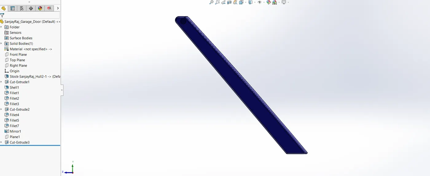
4.5. Garage Door
4.5.1. Design Overview
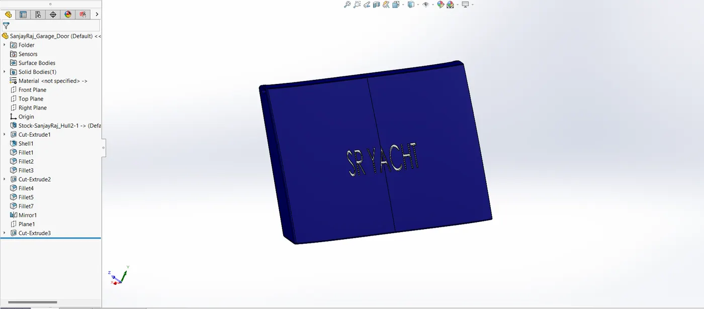
A crucial component of architecture, the garage door was made to be long-lasting, functional, and aesthetically pleasing. This concept places a strong emphasis on mobility and automation mechanism compatibility.
4.5.2. CAD Modelling Process
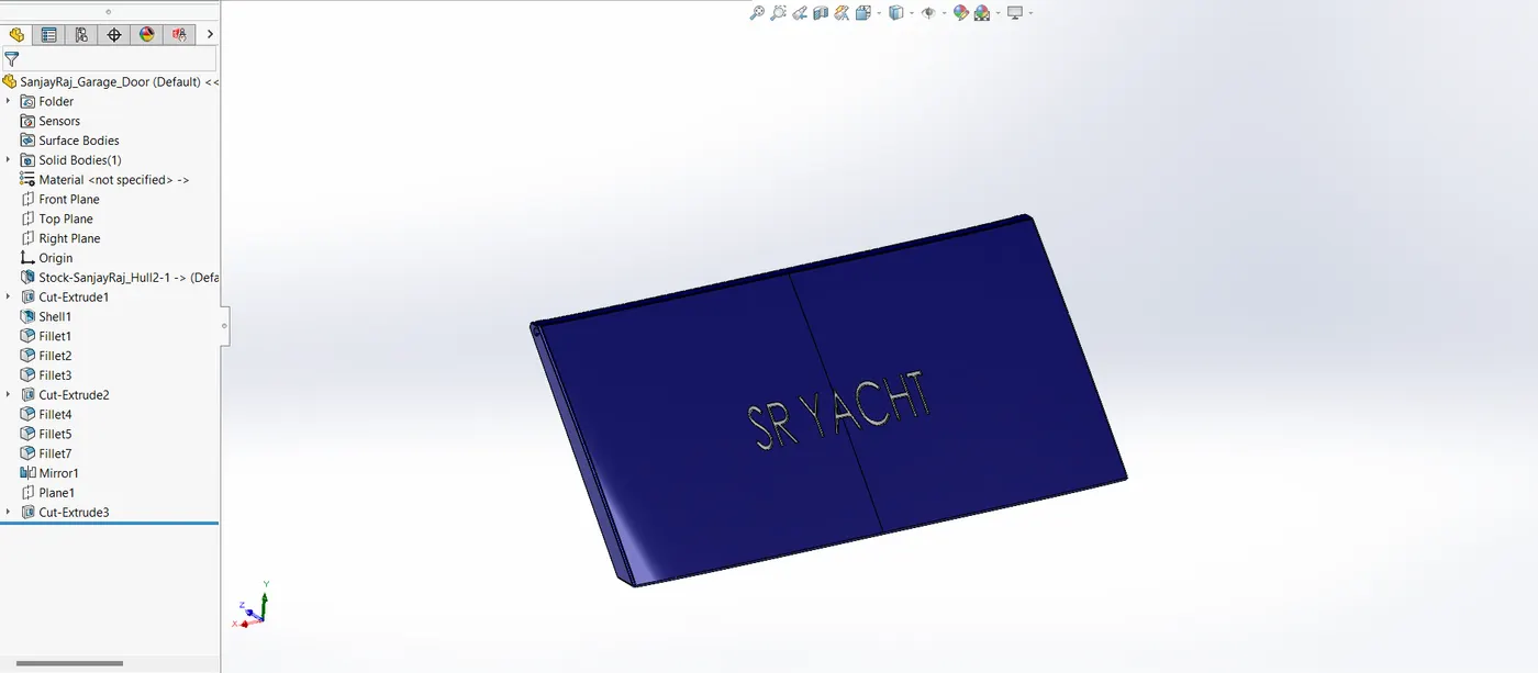
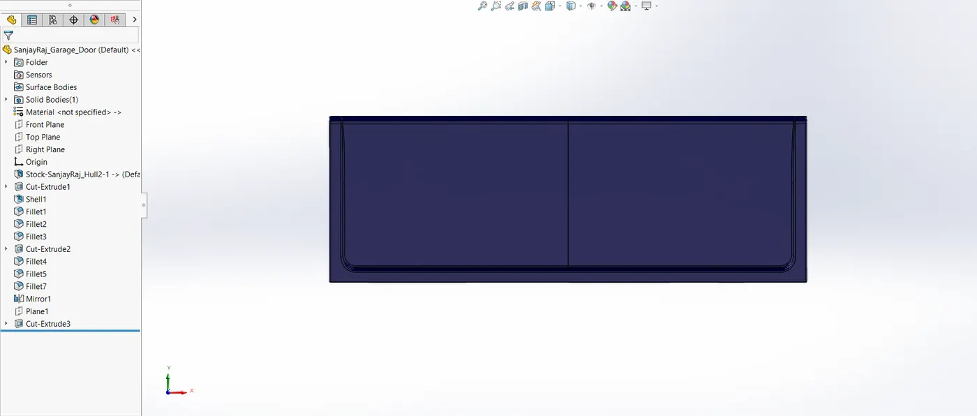
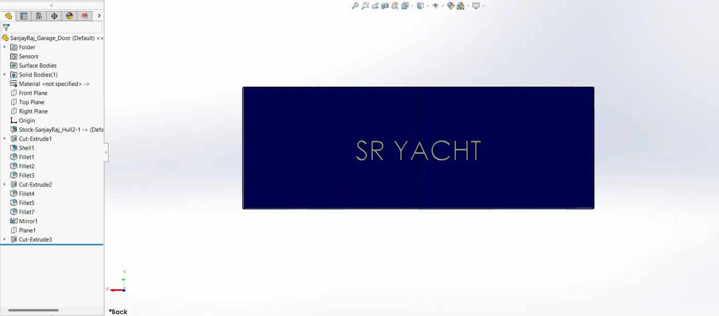
It is an excised portion of the hull that serves as the garage door's base. A garage door has the following essential components
- Cut extrude: used to cut the unwanted part or create a hole in the extruded item.
- Shell: utilized to provide thickness to the solid model.
- Fillet: used to give edges and corners a rounded appearance.
- Mirror: utilized to create a whole, solid body by mirroring the other half.
4.6. Front, Rear, and Middle Seat
4.6.1. Design Overview
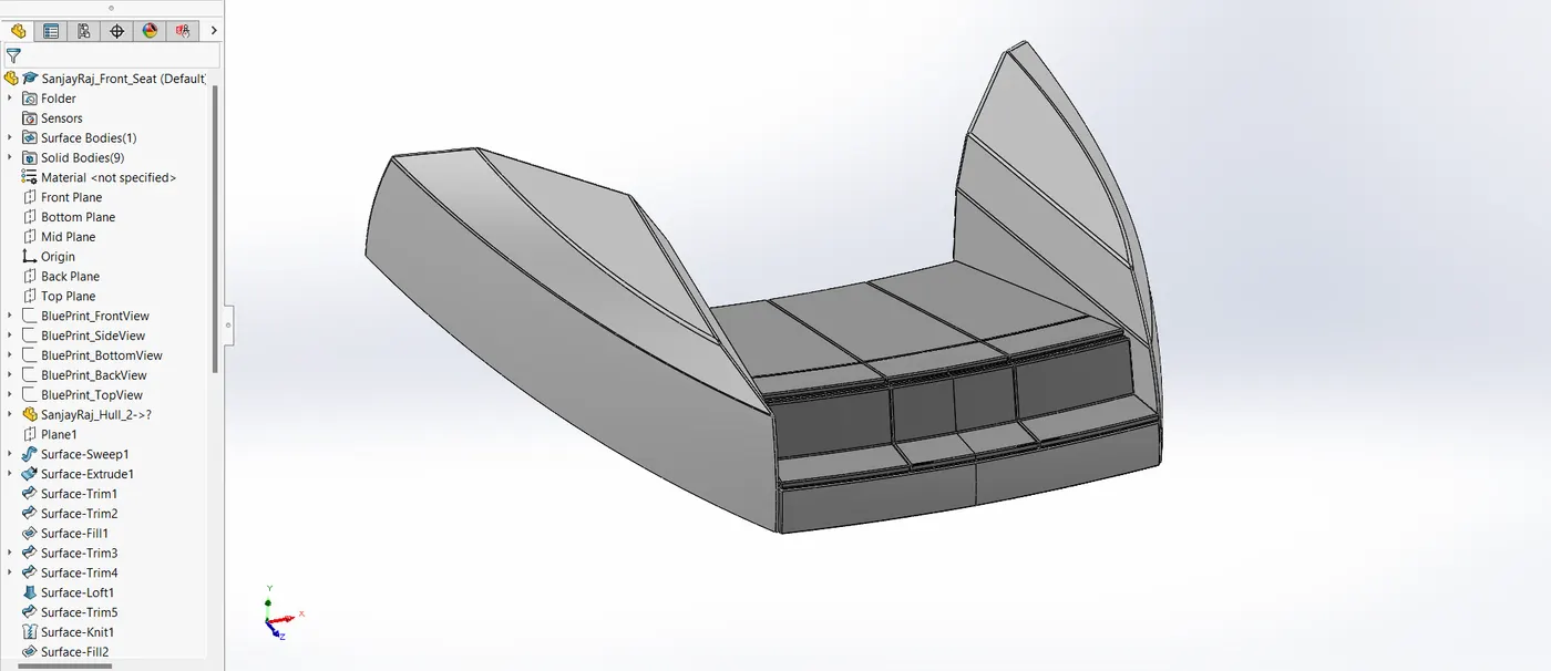
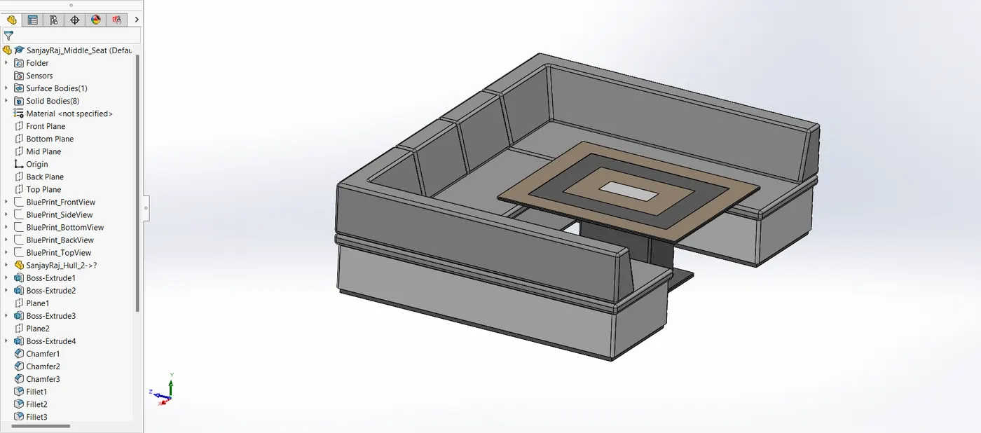
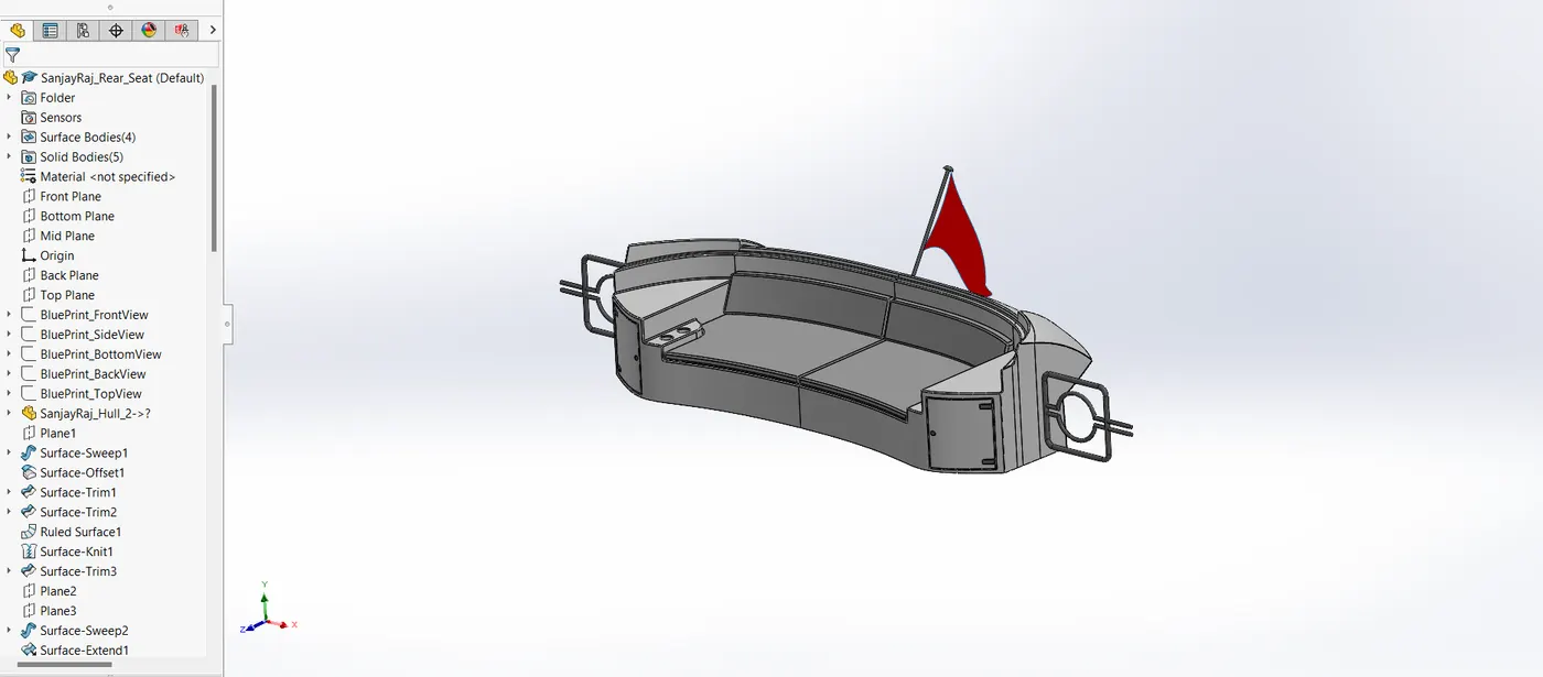
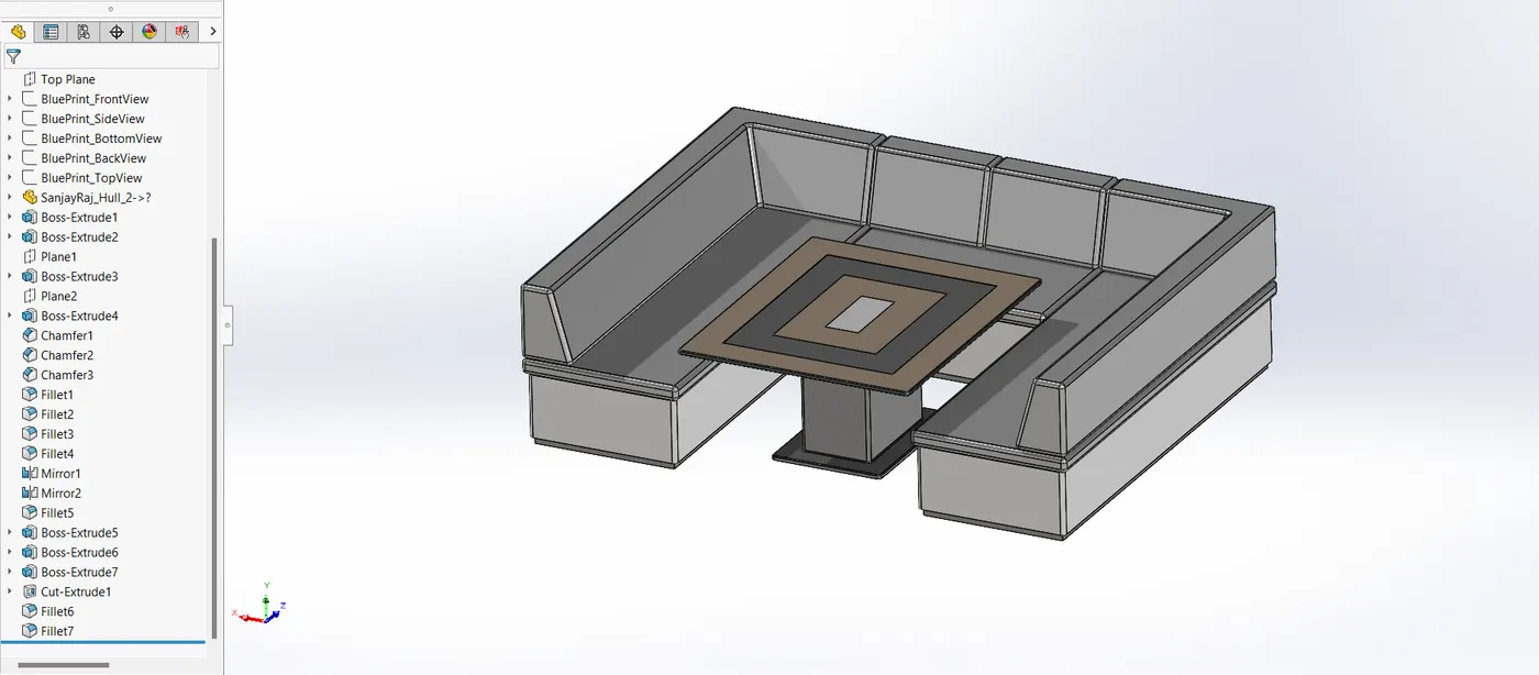
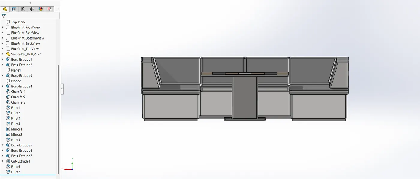
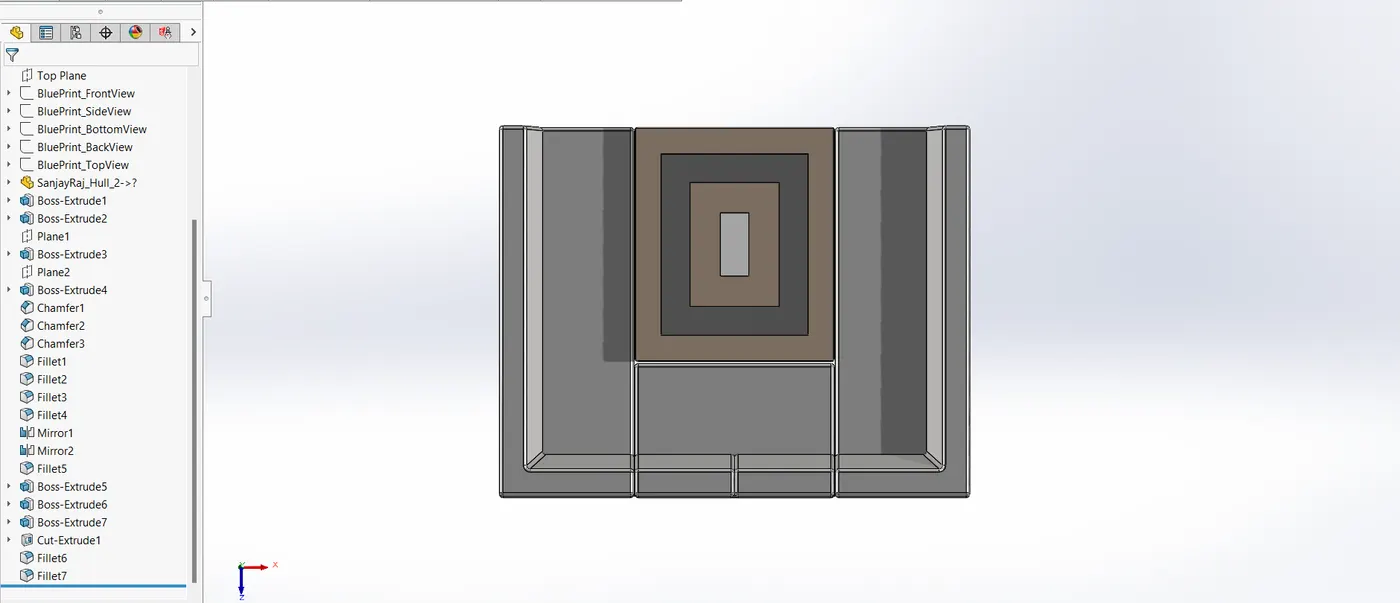
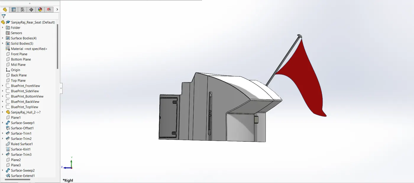
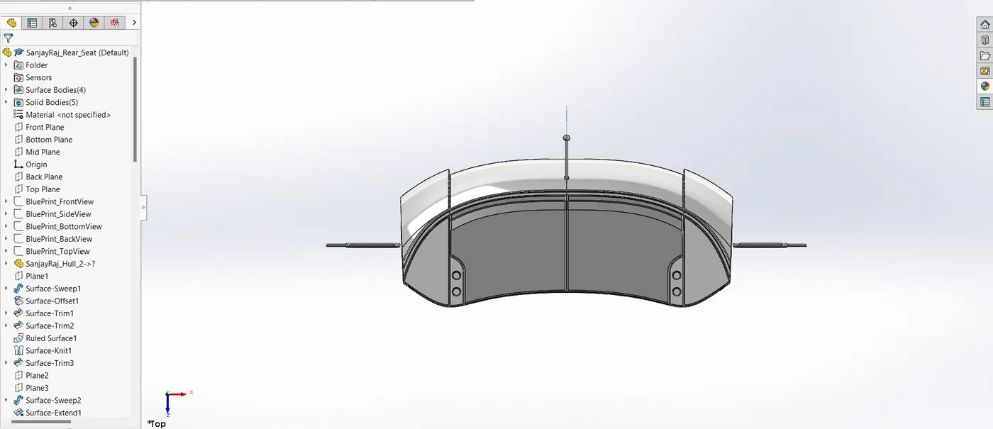
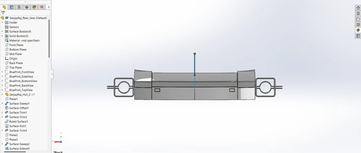
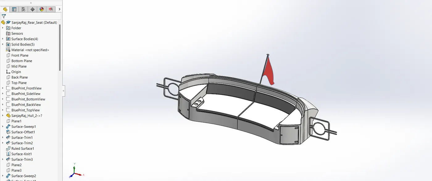
There should be enough of seats on the hull for passengers to enjoy the surroundings because the Predator yacht is known to be a sun-seeker. There will be seats on the yacht's front, centre, and back in consideration of this demand. The ergonomics of the yacht are reflected in the design of these seats. The middle seat is typically part of the social or lounge area of the yacht, providing comfortable seating for passengers during leisure or dining activities. The rear seat, often located in an open-deck or recreational area, is designed for maximum seating capacity and durability under outdoor marine conditions.
Front Seat
Middle Seat
Rear Seat
4.6.2. CAD Modelling Process
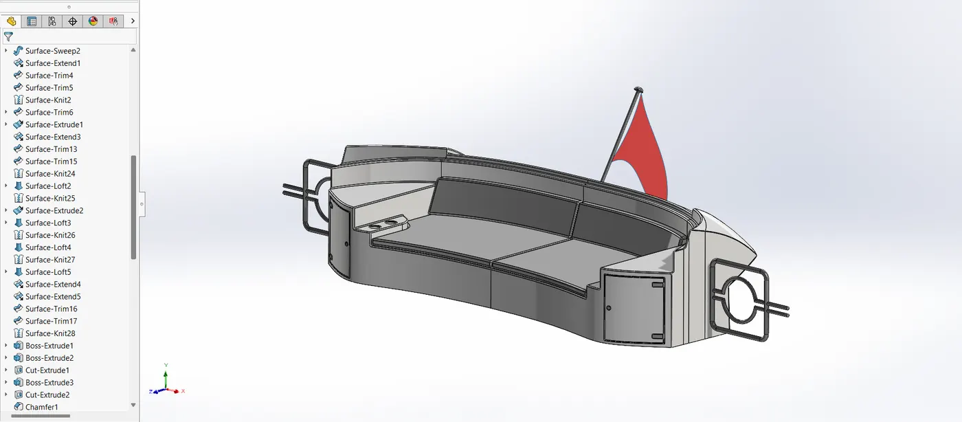
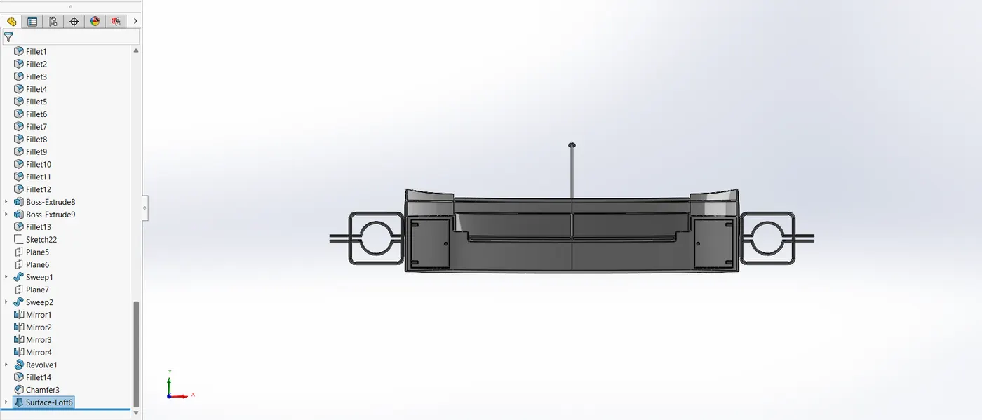
The front seat was modelled with a focus on functionality and premium aesthetics. The middle seat was designed to prioritize luxury and functionality. The rear seat was modelled to be sturdy, spacious, and weather-resistant. The following tools and techniques were utilized,
- Surface loft: Surface loft is the process of creating a surface with a minimum of two profile curves and two guiding curves.
- Surface knit: Knitting two or more surfaces is known as surface knitting.
- Cut extrude: used to cut the unwanted part or create a hole in the extruded item.
- Chamfer: Used to give edges and corners a tapered shape.
- Mirror: utilized to reflect half of the front seat to the other side.
- Surface Sweep: To sweep the surface, use a surface sweeper.
- Surface trim: Surface trim is a tool for surface trimming.
- Surface fill: four boundary curves are utilized to fill the surface.
- Boss extrude: used to create a solid body from 2D sketch.
- Fillet: used to give round shape to the corners & edges.
- Surface offset: used to offset the surface.
- Ruled surface: used to extend the surface in an angle using curve or line.
- Surface extend: used to extend the surface.
- Surface extrude: used to extrude the surface.
- Sweep: used to form helical shape & pipe using a profile sketch & guide curve to give a path to the profile sketch.
- Revolve: used to revolve a closed sketch about an axis by giving one of the lines as an axis.
Front Seat
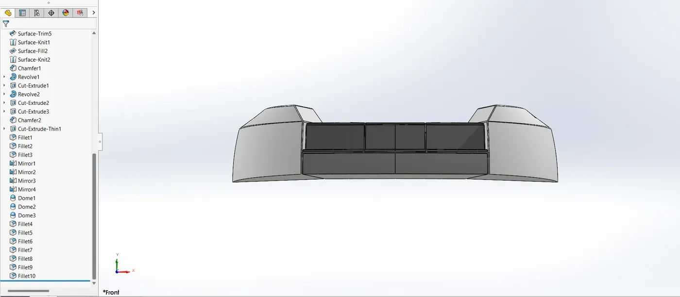
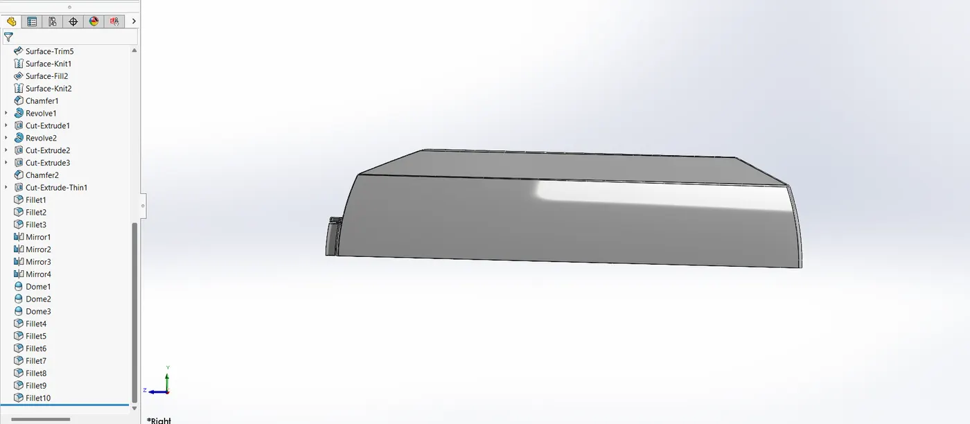
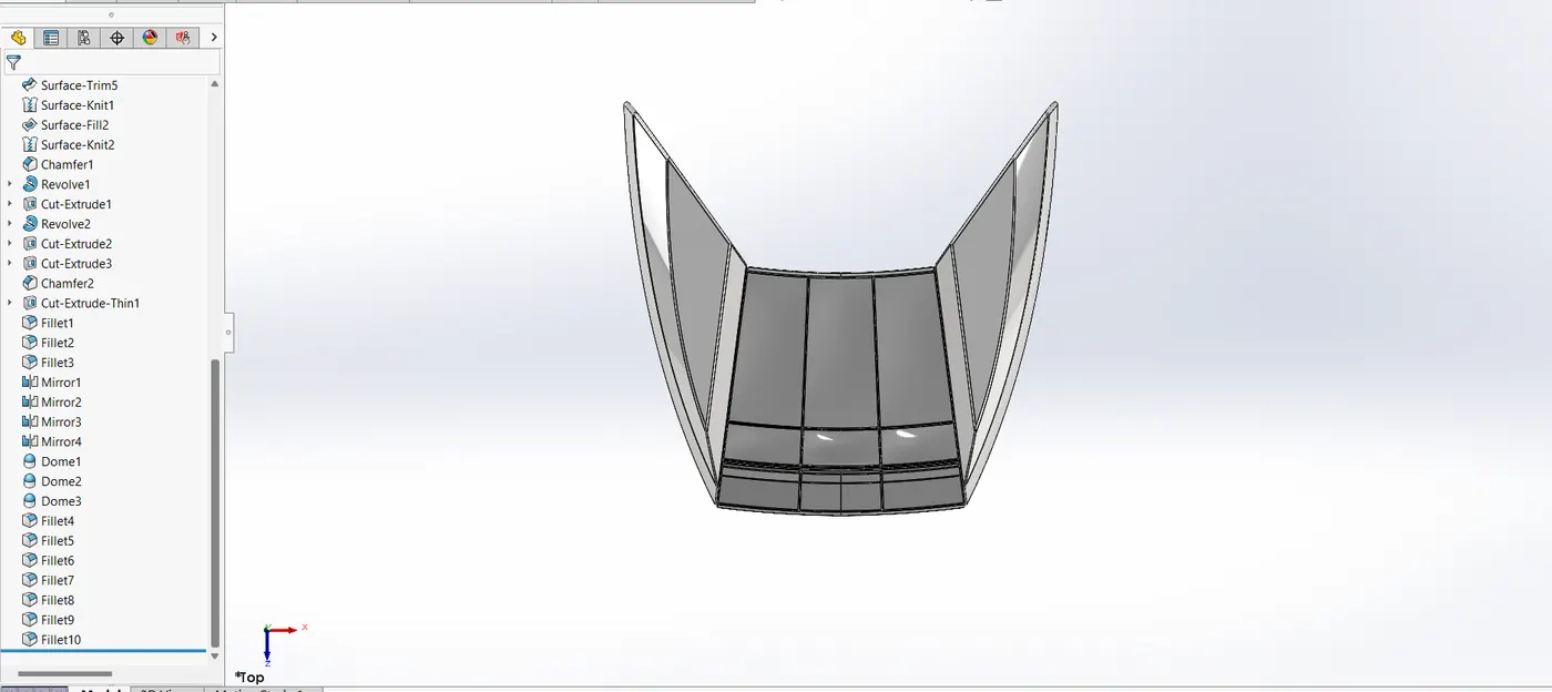
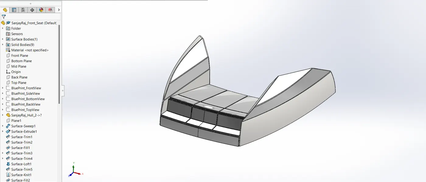
Middle Seat
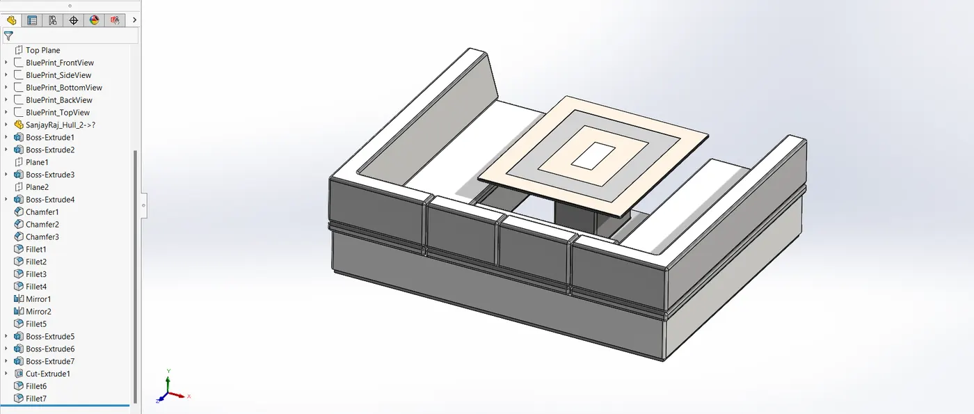
Rear Seat
4.7. Superstructure
A yacht's superstructure is intended to,
- Improve both aerodynamics and appearance.
- Provide areas that are useful, such lounges, cabins, and navigation areas.
- Assure safety and stability in maritime settings.
4.7.1. Design Overview
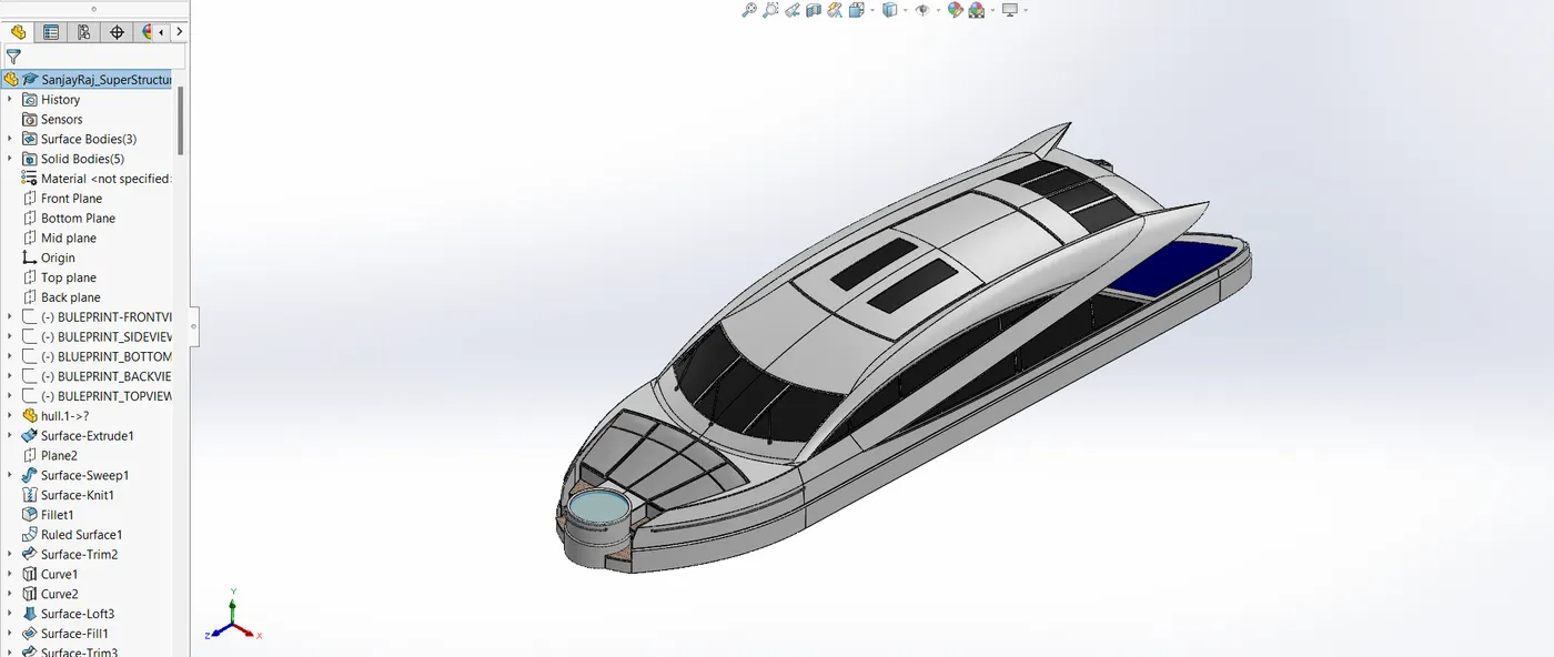
An existing structure that extends upward above a baseline is called a superstructure. A variety of physical structures, including buildings, bridges, and ships, are referred to by this name. The components of a ship or boat that protrude above its main deck, such as sailboats, fishing boats, passenger ships, and submarines, are referred to as the superstructure.
4.7.2. CAD Modelling Process
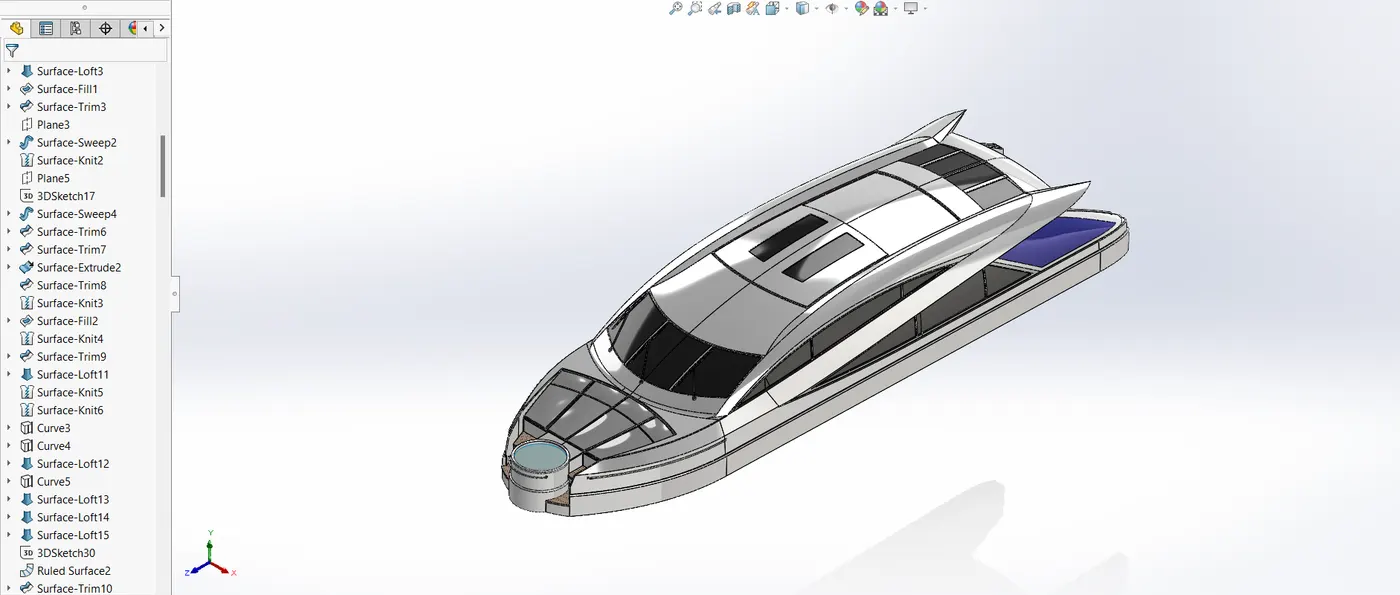
In the superstructure, the hull's offset surface serves as a base reference, and the blueprint setup is utilized to draw the sketches on the appropriate plane. It is positioned above the hull. It has the following characteristics,
- Surface extrude: is the process of extruding the surface.
- Surface sweep: To sweep the surface, use a surface sweeper.
- Curve: Curves are made using two 2D sketches that are drawn into two distinct planes and are used as profile curves or guide curves to produce surfaces.
- 3D sketch: a 3D sketching tool. It is utilized in this section to connect curves' end points.
- Trim surface: Surface trim is a trim tool that is used to trim the surface using surface or sketch elements.
- Surface knit: Surface knitting is a technique used to stitch separate surfaces together.
- Ruled surface: a surface that is extended at an angle by a line or curve.
- Surface loft: two guide curves and two profile curves are utilized to construct a surface.
- Surface extend: a tool for surface extension.
- Surface extrusion: a method of surface extension.
- Surface offset: a technique for separating the surface from the base.
- Split line: this sketch component is utilized to divide the face.
- Delete face: this function is used to remove the face.
- The closed sketch is extruded using the boss extrude.
- Cut extrude: this method is used to cut the unwanted part or make a hole in the extruded part.
- Fillet: utilized to give edges and corners a round form.
- Chamfer: utilized to give edges and corners a tapered form.
- Mirror – used to mirror the half portion of superstructure to its opposite side using mid plane as a mirror face.
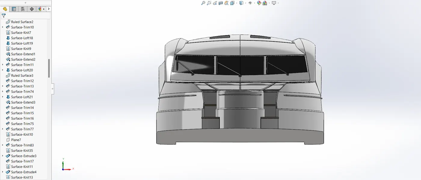
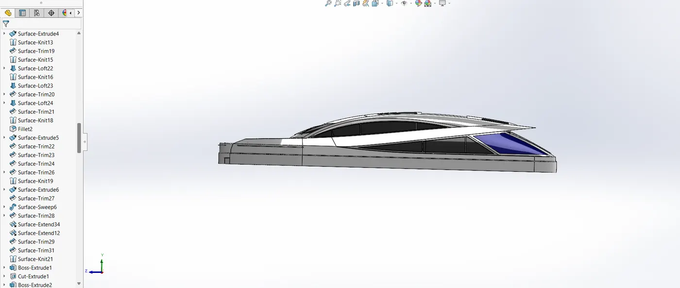
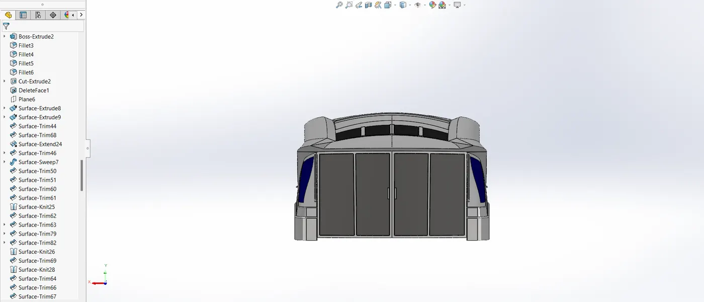
4.7.3. SPECIAL FEATURES OF THE SUPERSTRUCTURE
The streamlined shape of the superstructure minimizes drag, contributing to the yacht's overall efficiency. The functional space of the superstructure includes,
- Bridge area: For navigation and control.
- Passenger cabins: Ensuring comfort and luxury.
- Deck area: Open spaces for relaxation or entertainment.
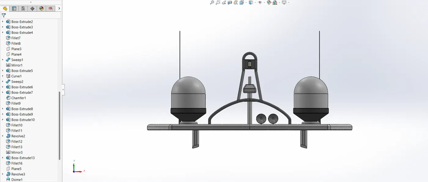
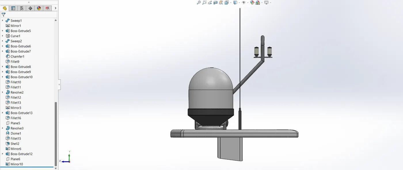
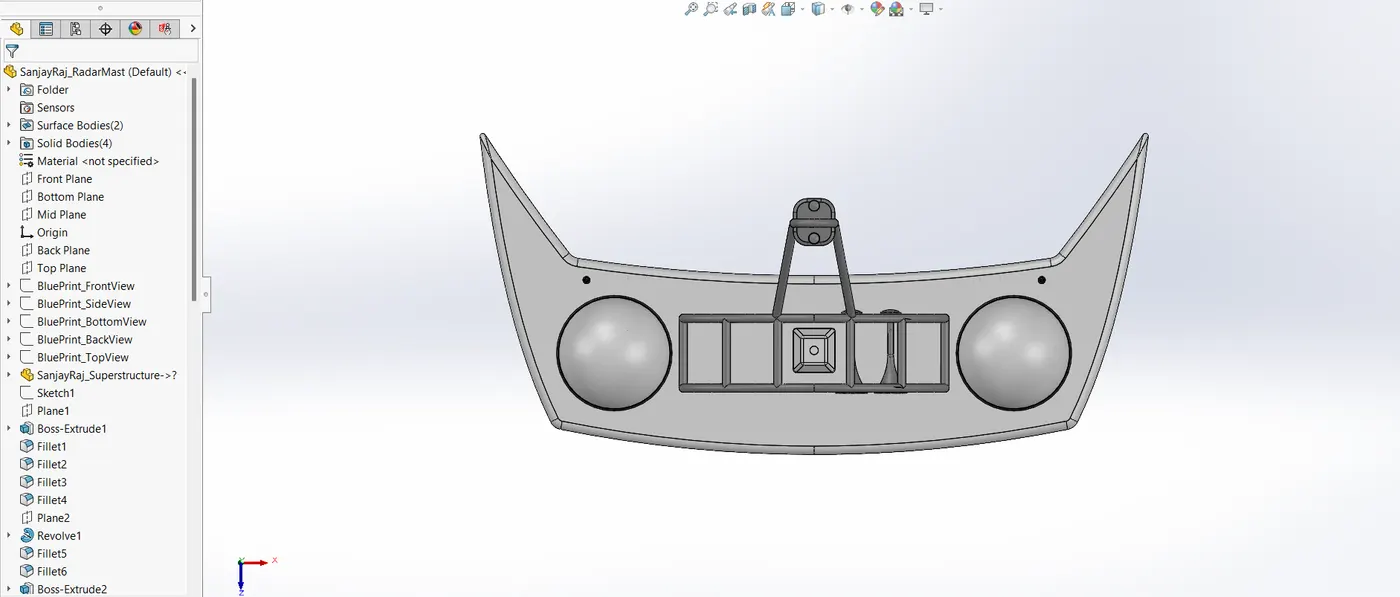
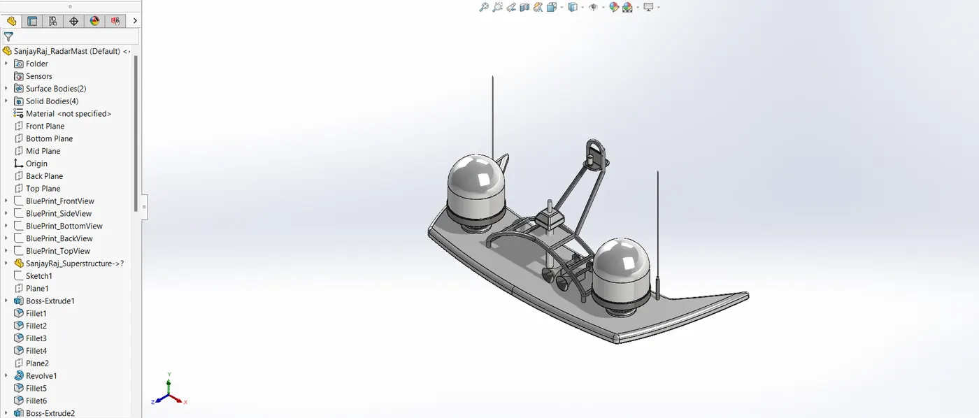
4.8. Radar Mast
Stability and signal efficiency are guaranteed by the navigation and communication equipment housed in the radar mast.
4.8.1. Design Overview
One component that is positioned above the superstructure is the radar mast. We utilize the blueprint as a guide for designing the radar tower, and we also make a surface in the hull design for later use. To make solid bodies, we mostly employed the extrude and cut-extrude features. Horns and a dome are created using the revolve feature.
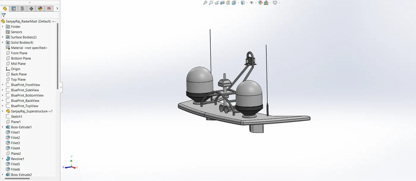
4.8.2. CAD Modelling Process
- Boss Extrude: The closed sketch is extruded using the boss extrude tool.
- Revolve: This function uses one of the lines as an axis to rotate a closed sketch around it.
- Sweep: A profile curve can be swept along a predetermined route using the sweep function.
- Curves: Curves are made using two 2D sketches that are drawn into two distinct planes and are used as profile curves or guide curves to produce surfaces.
- Fillet: used to give edges and corners a rounded appearance.
- Chamfer: used to give edges and corners a tapered shape.
- Shell: used to make a body that is hollow.
- Combine: a method for combining solid objects.
- Mirror: Using the midplane as a mirror face, the mirror is used to reflect half of the superstructure to the other side.
4.9. Final Assembly of Yacht
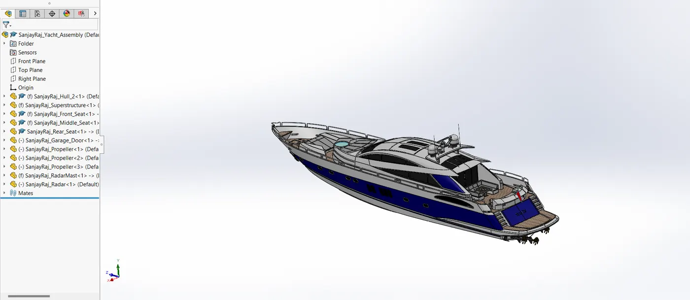
4.9.1. Assembly Overview
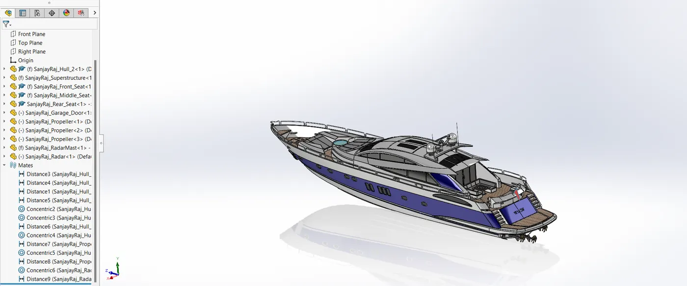
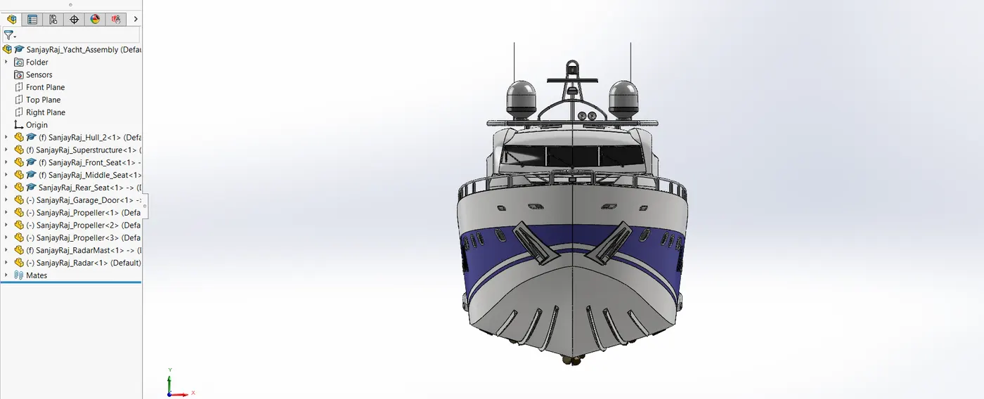
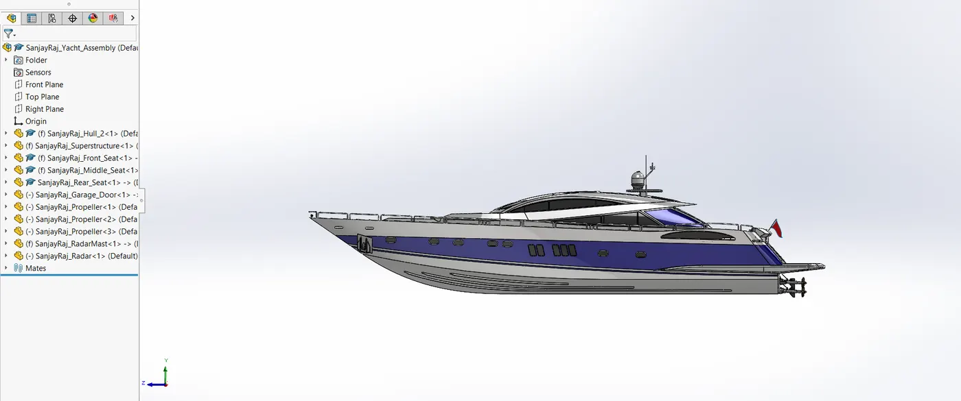
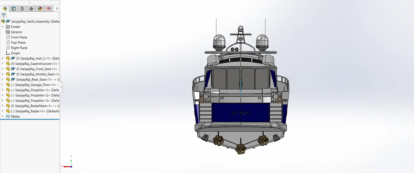
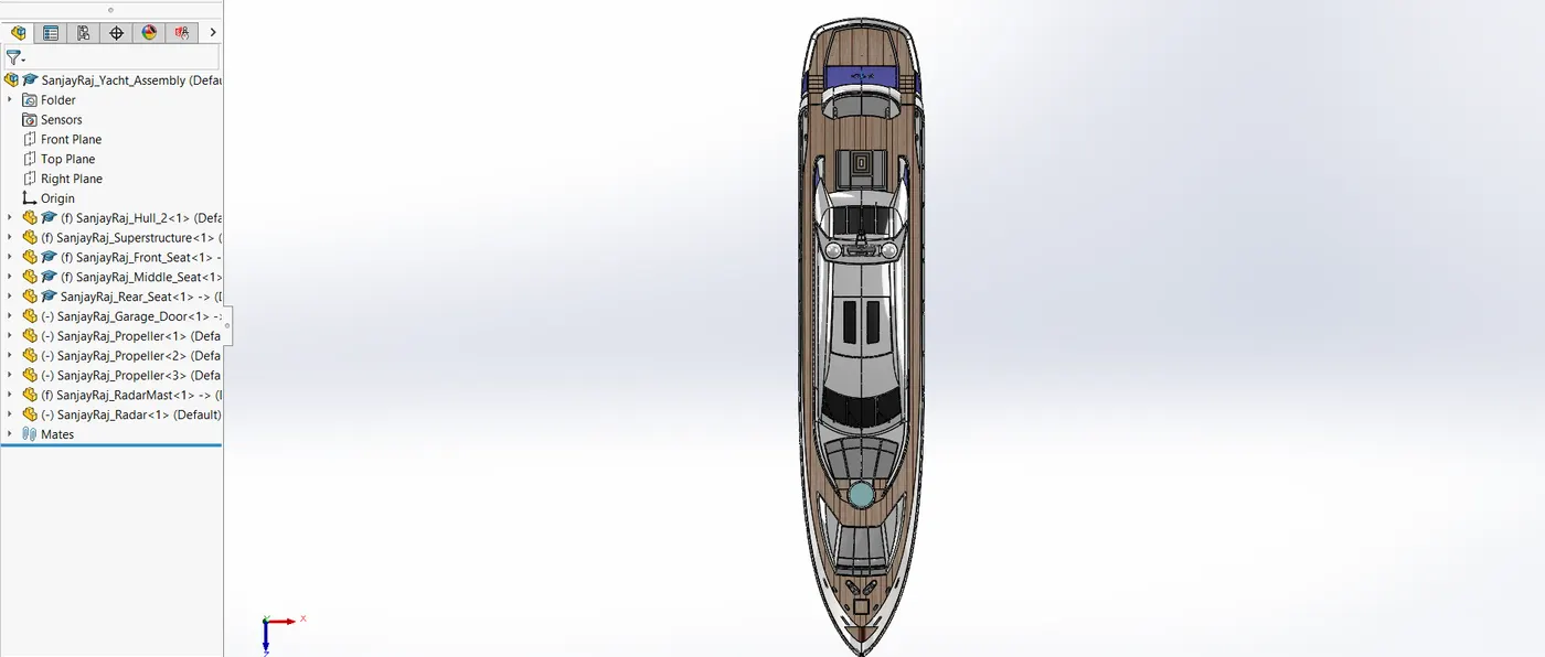
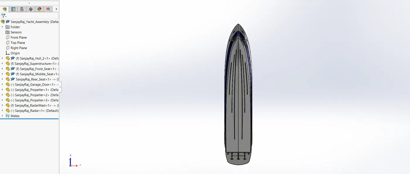
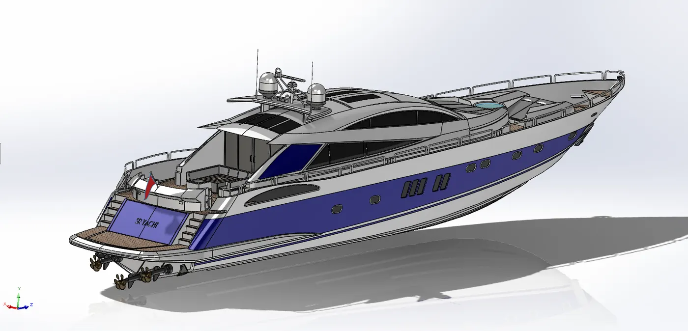
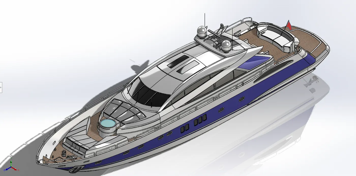
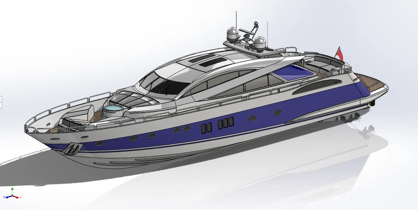
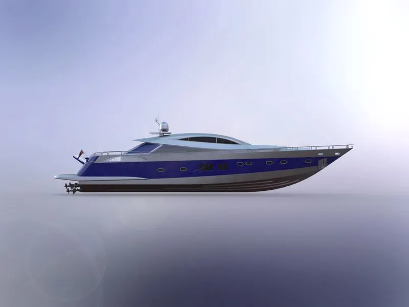
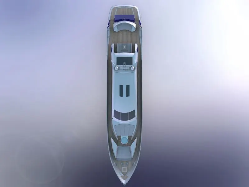
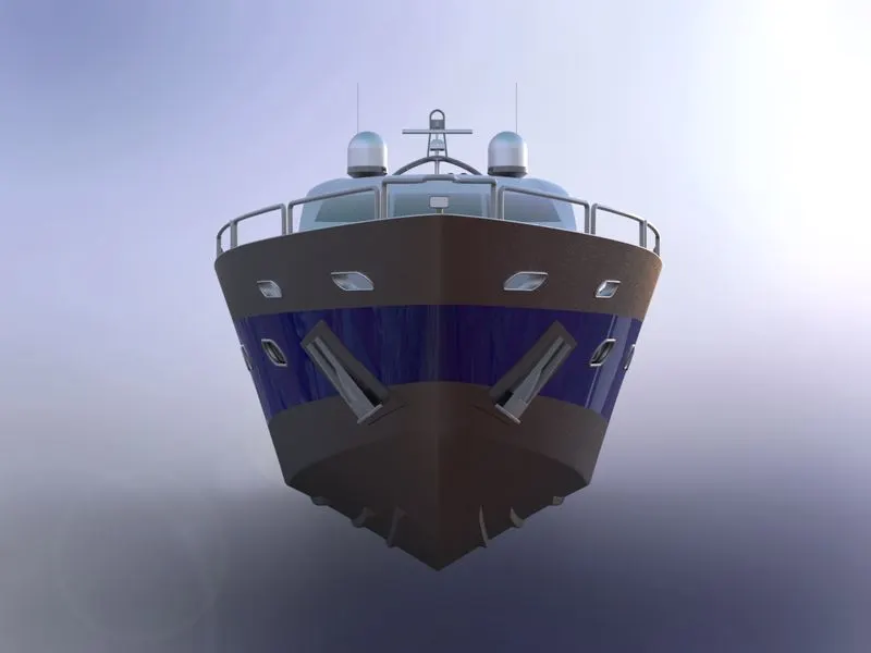
The entire yacht model was created by assembling all the parts in the SolidWorks assembly environment.
4.9.2. Assembly Process
- Mates: Component alignment is achieved by applying coincident and concentric restrictions.
- Interference detection: Fitting problems were fixed to prevent overlaps.
- Rendering: Added realistic materials, textures, and decals.
5. CONCLUSION
Using SolidWorks, the project successfully modelled and put together a complete yacht. While the rendering process brought the concept to life with stunning images, sophisticated CAD tools and processes guaranteed accuracy.
File Link - https://drive.google.com/file/d/1NyMh1fJrnTFsn5f1vHW-JqUlI6SJ4ctX/view?usp=sharing