Radar Mast & Final Assembly of Yacht
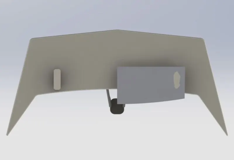
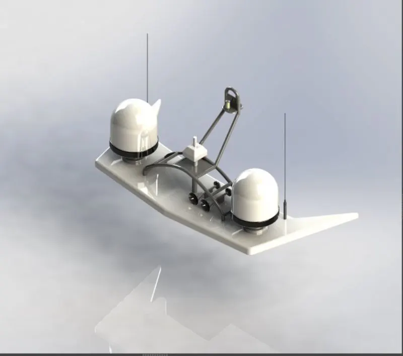
Radar
front view
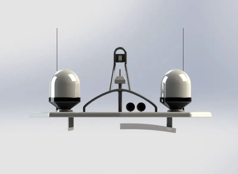
back view
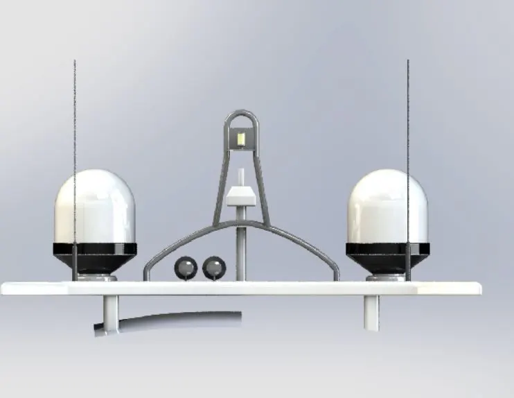
side view
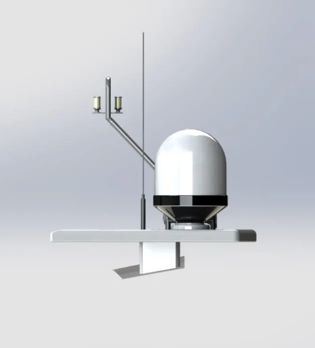
top view
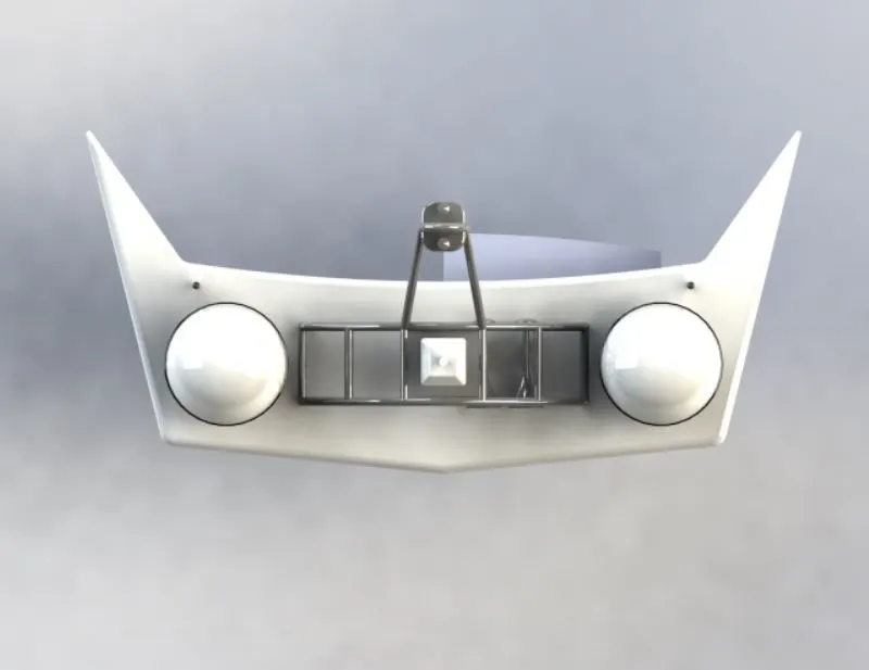
bottom view
isomatric view
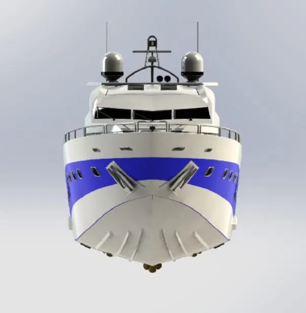
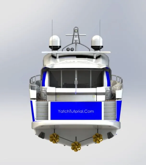
ASSEMBLY OF YATCH
front view
back view
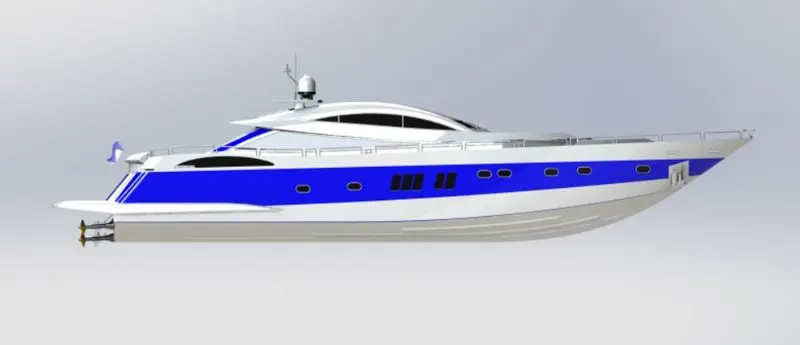
side view
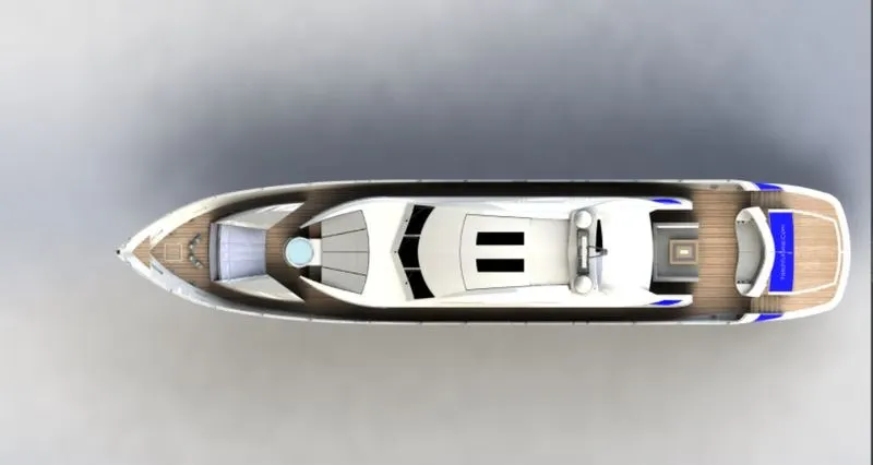
top view
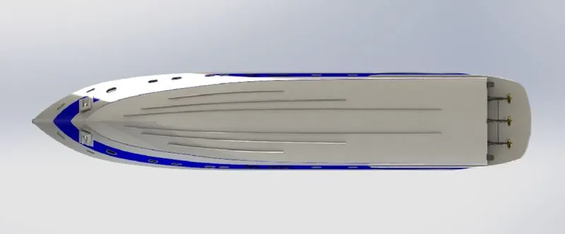
bottom view
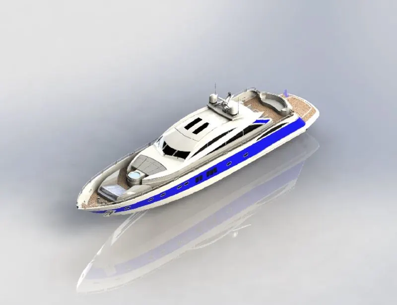
isomatric view
camera view
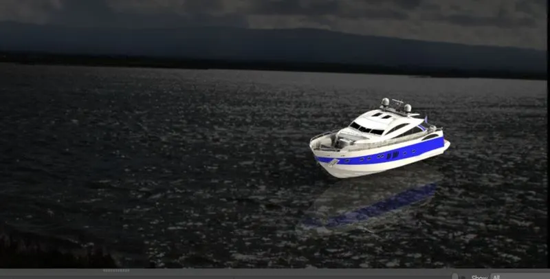
HERE IS THE COMLPETE REPORT OF THE MODELING THE YACH BY SOLIDWORKS
Indroduction:-
This project report is about 3D modelling, assembling and rendering a yacht. In super structure, First of all we ceate the surface bidy later it cinverted in to solid body using SolidWorks for 3D modelling & SolidWorks. Visualize/Photoview360 for photo realistic rendering.
The modelling of Yacht involves 3 stages
- Modelling of individual parts
- Assembling of the parts
- Rendering the components
The Yacht consists of the following parts
- Hull
- Superstructure
- Radar
- Radar mast
- Garage door
- Propeller
- Front, Middle, and Rear seat
During the modelling of the above parts, the reference planes are created wherever necessary, and since it is a cosmetic model tolerance is not considered deliberately.
ALL THESE PARTS ARE CREATED ACCODINGLY BLUE PRINT OF THE YATCH
1. HULL
Hull is the base of the yacht and it is a symmetric model.
Therefore it is enough to model one half and the other half could be mirrored.
First, the hull is developed in surface modelling, then after completing the model by surface it is converted to solid and proceeded with solid modelling. This is because hull consists of surface with complex curvature, therefore it is wise to model with surface then convert it as solid.
Blueprint setup – used as a base to sketch the curves & outlines to create the surface.
Surface loft – used to create a surface using at least 2 profile curves & 2 guide curves.
Curve – used as a profile curve or guide curve to form surface & created using 2 2D sketch which is sketched into two different planes.
Surface trim – used to trim the surface.
Surface extrude – used to extrude the surface.
Surface knit – used to knit two or more than two surfaces.
Surface fill – used to create a surface using 4 boundary curves.
Shell – used to hollow the solid model with some thickness
Boss extrude – used to create a solid body from 2D sketch.
Cut extrude – used to cut the extruded part to form hole or cut the undesirable part.
Fillet – used to give round shape to the corners & edges .
Chamfer – used to give a taper to the corners & edges.
Linear pattern – used to pattern the feature over a linear path
Dome – used to create a dome over a solid part.
Split – used to cut out the solid part from the body.
Surface offset – used to offset the surface.
Delete face – used to delete the face.
sweep – used to form helical shape & pipe using a profile sketch & guide curve to give a path to the profile sketch.
Revolve – used to revolve a closed sketch about an axis by giving one of the line as an axis.
Mirror - used to mirror the half portion of hull to form a complete solid body.
- Super Structure
It is placed on the top of the hull. It is also a symmetric model therefore it is enough to model one half so that the other half could be mirrored. It is modelled in a way same as hull, the model is started in surface modelling with a deck surface imported from hull as reference. The desired surfaces are modeled and the surface model is converted into solid and proceeded with solid modelling.
Surface extrude - used to extrude the surface.
Surface sweep – used to sweep the surface.
Curve - used as a profile curve or guide curve to form surface & created using 2 2D sketch which is sketched into two different planes.
3D sketch – used to sketch in 3D. in this part it is used to join the end points of curves.
Surface trim – used to trim the surface using surface or sketch entities as a trim tool.
Surface knit – used to knit the individual surface to combine it.
Ruled surface - used to extend the surface in an angle using curve or line.
Surface loft – used to create a surface using 2 guide curves & 2 profile curves.
Surface extend – used to extend the surface.
Surface extrude – used to extend the surface.
Surface offset – used to offset surface from the base .
Split line – used to split the face using sketch entity.
Delete face – used to delete the face.
Boss extrude – used to extrude the closed sketch.
Cut extrude – used to cut the extruded part to create hole or cut the undesirable part.
Fillet – used to give round shape to corners & edges.
Chamfer – used to give taper shape to corners & edges.
Mirror – used to mirror the half portion of superstructure to its opposite side using mid plane as a mirror face.
- Radar
Radar is a device used for detecting Radio signals and maintain the communication with the oather ships and administration. It is a very important device in any yacht/ship. It is mated with a part called radarmast and placed on the topmost part of the yacht. It is modelled only in solid modelling. it is a symmetric model so the other half is mirrored. The name is engraved using text and cut extrude (offset from surface).
Boss extrude - used to extrude the closed 2D sketch upto desirable height.
Cut extrude – used to cut the extruded part to make hole or cut the undesirable part.
Fillet – used to give the rounded shape to the corners & edges with a required radius.
Sketch pattern – used to pattern features aver a sketched point.
Mirror – used to mirror the body by giving the mirror face as reference.
Spit line – used to cut the face into parts. In radar, this feature is used to print the text over it.
Text – it is a 3D text to be printed over the radar, using split line command.
- Radarmast
It is a device that comes along with radar it is used to control the position and direction of radar. It also processes the signals which are sent and received. It is modelled based on the deck surface imported from the superstructure
Boss extrude – used to extrude the closed sketch.
Revolve – used to revolve a closed sketch about an axis by giving one of the line as an axis.
Sweep - used to sweep a profile curve along a defined path.
Curve – used as a profile curve or guide curve to form surface & created using 2 2D sketch which is sketched into two different planes.
Fillet - used to give round shape to corners & edges.
Chamfer - used to give taper shape to corners & edges.
Shell – used to create a hollow body.
Combine – used to combine to solid bodies.
Mirror – used to mirror the half portion of superstructure to its opposite side using mid plane as a mirror face.
- Garage Door
This part is modelled in a solid model which was saved when split command is used during modelling hull. The part is retrieved and is used for the construction of the garage door. It is a symmetric model, therefore the other half is mirrored. The name is engraved using text and cut extrude (offset from surface)
Cut extrude - used to cut the extracted part of the hull.
Shell - used to hollow the solid body with some thickness.
Fillet - used to give the round shape to corners & edges.
Mirror - used to mirror the half portion of hull.
- Propeller
Propeller is submerged inside water. Propeller is the main component for the navigation of yacht, it receives power from the engine, it helps the yacht to move forward or backward by pushing the water in opposite direction, for instance if the ship is moving forward the propeller pushes the water backward and vice versa
Revolve - used to rotate the closed 2D sketch about a central axis.
Cut extrude - used to cut the extruded part. In this part, this feature is used to make a hole over the revolved part.
Loft – used to create vanes of propeller.
Circular pattern – used to copy the pattern in a circular path.
Fillet – used to give the rounded shape to all the corners.
7.FRONT SEAT
Surface loft - used to create a surface using at least 2 profile curves & 2 guide curves.
Surface knit - used to knit two or more than two surfaces.
Cut extrude - used to cut the extruded part to form hole or cut the undesirable part.
Fillet - & edges Used to give round shape to the corners.
Chamfer - Used to give taper shape to the corners & edges.
Mirror – used to mirror the half portion of front seat to opposite side.
In front seat part, offset surface of hull is used as a base reference. It consists of following features:
Surface sweep – used to sweep the surface.
Surface trim – used to trim the surface.
Surface fill – used to fill the surface using 4 boundary curves.
8. MIDDLE SEAT
In middle seat part, offset surface of hull is used as a base reference. It consists of following features:
Boss extrude - used to create a solid body from 2D sketch.
Chamfer - Used to give taper shape to the corners & edges.
Fillet - Used to give round shape to the corners & edges.
Cut extrude – used to cut the extruded part.
Mirror – used to mirror the half portion of middle seat to opposite side.
9. RAER SEAT
In rear seat part, offset surface of hull is used as a base reference. It consists of following features:
Surface sweep – used to sweep the surface.
Surface offset – used to offset the surface.
Surface trim– used to trim the surface.
Ruled surface – used to extend the surface in an angle using curve or line.
Surface knit - used to knit two or more than two surfaces.
Surface extrude - used to extrude the surface.
Surface extend – used to extend the surface.
Surface loft - used to create a surface using at least 2 profile curves & 2 guide curves.
Boss extrude - used to create a solid body from 2D sketch.
Sweep - used to form helical shape & pipe using a profile sketch & guide curve to give a path to the profile sketch.
Revolve – used to revolve a closed sketch about an axis by giving one of the line as an axis.
Fillet - Used to give round shape to the corners & edges.
Chamfer - Used to give round shape to the corners & edges.
Mirror - used to mirror the half portion of rear seat to opposite side.
Conclusion
The Project helped in understanding different tools and features that can be used in solidworks to design, model, assemble and render different Machines similar to the Yacht we designed. The project covered almost all the tools used in Solidworks and also some basics of sheet metal design and helped in understanding those tools due to practical application of the same.
NOTE - IN THIS FILE I PROVIDE '.IGS AND .DWG AND .RAR FORMATE FILES