Radar Mast & Final Assembly of Yacht
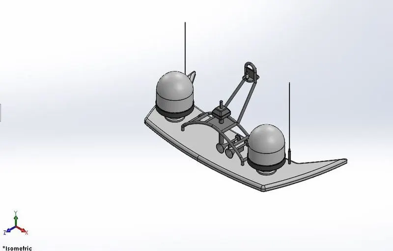
1.RADARMAST
ISOMETRIC VIEW
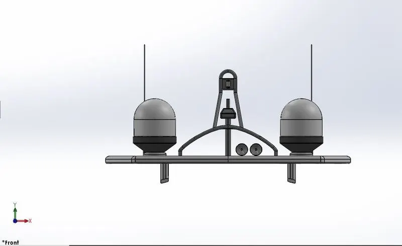
FRONT VIEW
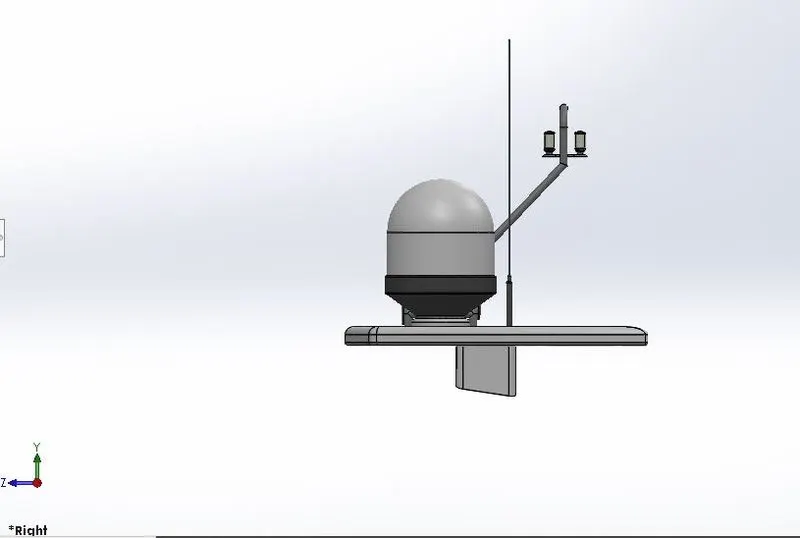
SIDE VIEW
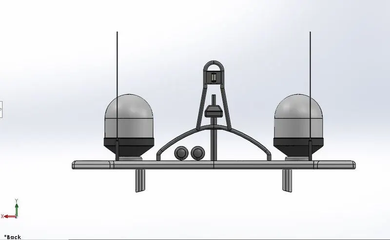
BACK VIEW
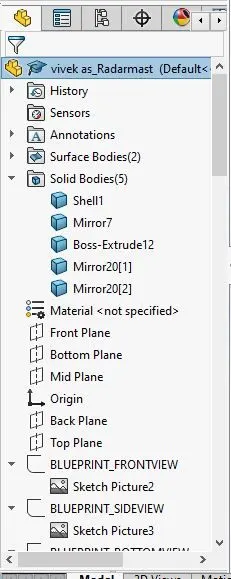
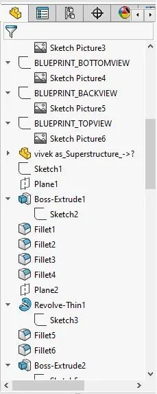
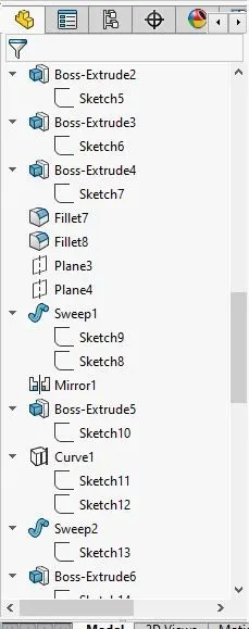
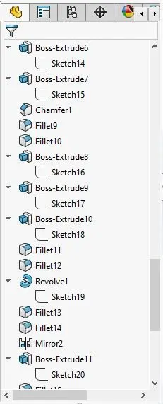
RADARMAST FEATURE TREE
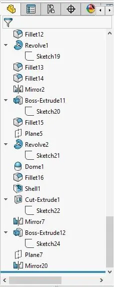
2. YACHT ASSEMBLY
ISOMETRIC VIEW
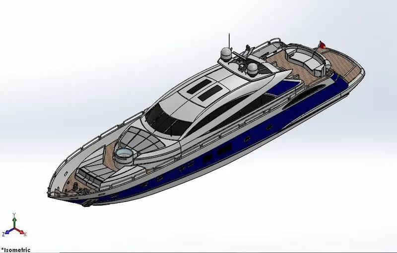
FRONT VIEW
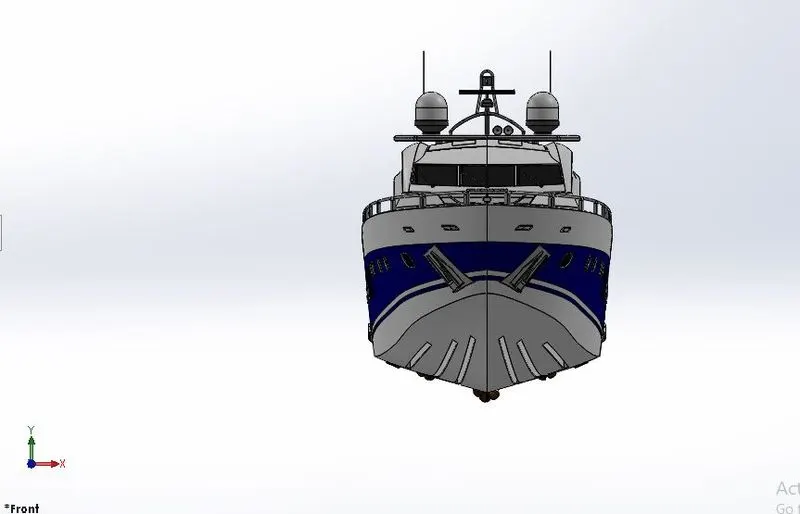
SIDE VIEW
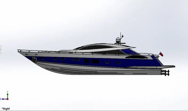
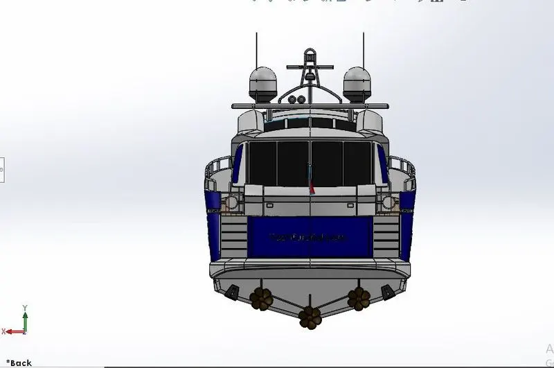
BACK VIEW
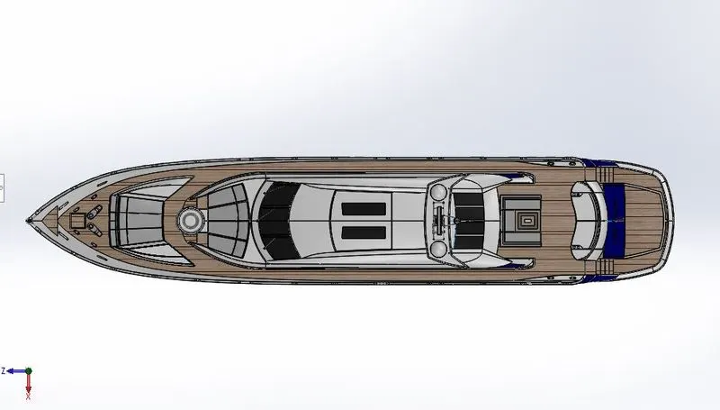
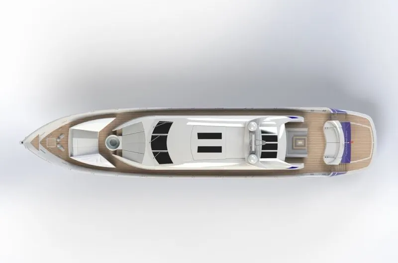
TOP VIEW
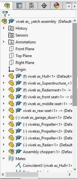
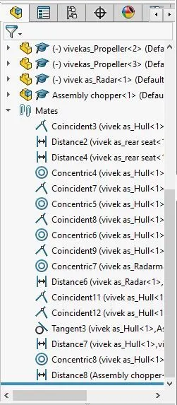
ASSEMBLY FEATURE TREE
MODELING AND RENDERING OF YACHT USING ULIMATE SOLIDWORKS
OBJECTIVE:
- The main objective of this project is to learn ULTIMATE SOLIDWORKS by modeling different parts of Yacht
- The exploration of tools that are used for the modeling yacht in solidworks
- To assemble the different parts modeled for the yacht
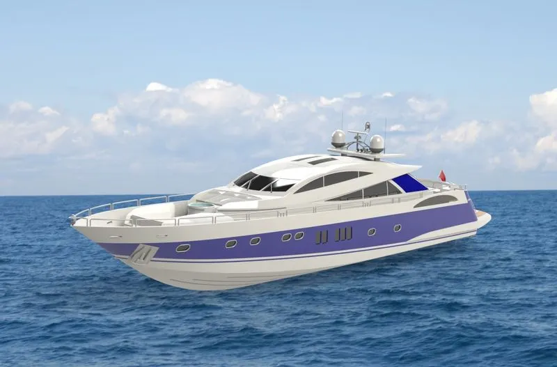
To create a photo-realistic view of the yacht by rendering the model using SOLIDWORKS Photo View360 and SOLIDWORKS Visualize.
INDRODUCTION
The SOLIDWORKS CAD software is a mechanical design automation application that lets designers quickly sketch out ideas, experiment with features and dimensions, and produce models and detailed drawings.By using Solidworks the designing the parts of an yacht to the final rendering done by the assembly of parts.
METHODOLOGY
The Design Methodology is explained by a flowchart given below.
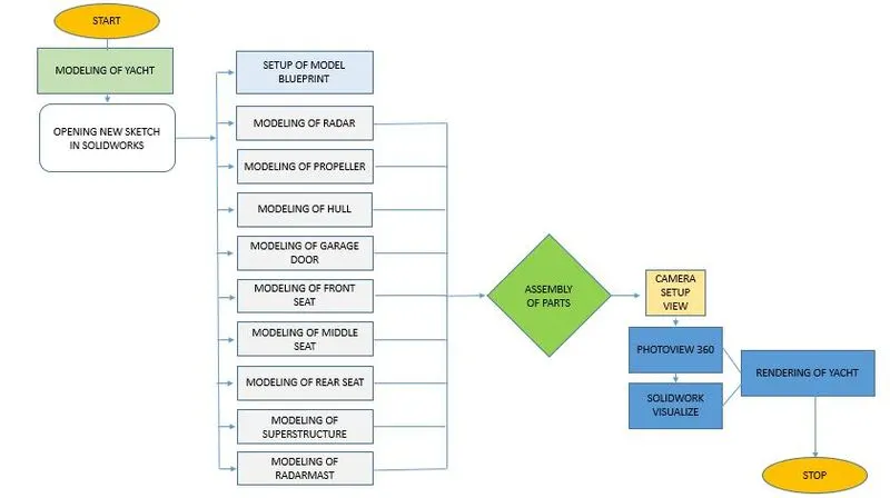
DESCRIPTION OF FEATURES:
SKETCH
- Sketch is the two dimensional representation of the model with respect to the plane/view from the outside of the model.Lines,Arcs,Spline,Circles,Rectangles are available in the sketch known as Entitles in Solid works
3D SKETCH
- 3D sketch is used to sketch lines,arcs,splines etc in the 3 dimensional x,y,x directions
OFFSET
- The offset entities tool allows us to create an offset of one or more sketch entities or using model edges or model faces
EXTRUDE BOSS/BASS
- An Extrude Boss/Base feature will allow you to take a 2D sketch and add thickness to it in the third dimension.
EXTRUDE CUT
- Extruded cut feature removes material from the part. The End Condition, Draft, and Thin Feature options are same as described in Extruded Boss/Base.
FILLET
- Fillet/Round creates a rounded internal or external face on the part. You can fillet all edges of a face, selected sets of faces, selected edges, or edge loops.
TRIM ENTITIES
- Select the trim based on the entities you want to trim or extend.Power trim is to trim the sketchs are in 2D on 3D planes.
LOFT BOSS/BASS
- Loft creates a feature by making transitions between profiles. A loft can be a base, boss, cut, or surface. You create a loft using two or more profiles. Only the first, last, or first and last profiles can be points.
DOME
- Select one or more planar or non-planar faces.Apply domes to faces whose centroid lies outside the face.This allows to apply domes to irregularly shaped contours.
SPLIT
- It is used to split one or more solid or surface bodies. To split a surface, the Trimming Surface must extend past the boundaries of the surface to split.
REVOLVE
- Revolves add or remove material by revolving one or more profiles around a centerline. You can create revolved boss/bases, revolved cuts, or revolved surfaces. The revolve feature can be a solid, a thin feature, or a surface.
DYNAMIC MIRROR
- Dynamic Mirror allows the user to mirror a sketch about a line while the user is creating their sketch. Depending on design intent this tool can save an immense amount of time.
COMBINE
- The common function allows you to add two bodies together, and keep the area that is common to them. To use this feature, we will select the common button, and then under Bodies to Combine, select the two bodies.
CHAMFER
- Chamfer tool creates a beveled feature on selected edges, faces, or a vertex. To create a chamfer
SHEEL
- The shell tool hollows out a part, leaves open the faces you select, and creates thin-walled features on the remaining faces. If you do not select any face on the model, you can shell a solid part, creating a closed, hollow model. You can also shell a model using multiple thicknesses.
LINEAR PATTERN
- The Linear Pattern Command is used to drive features, faces, or bodies in a linear direction.It is used to creat different number of instances required to create pattern linearly.
CIRCULAR PATTERN
The circular bobies/features are used to creat different number of instances required to create pattern circularity.
SURFACE MODELING
- Surface modeling gives you the ability to build out a visual representation of an object's exterior and its contours. In other words, it's a surface.
FILLED SURFACE
- The Filled Surface feature constructs a surface patch with any number of sides, within a boundary defined by existing sketches or curves
LOFTED SURFACE
- Loft Surfaces are surfaces generated by multiple 3D Curves or existing edges creating a smooth tangency between the selected curves.
SWEPT SURFACE
- Swept surfaces are surfaces that are generated from the section curve positioned along a path.
SURFACE TRIM
- Surface Trim is used to cut away material from the a surface.
SURFACE KNIT
- Surface Knit is used to knit the two free edges/open edges of the surfaces together.Also it reduced the gap between the two edges of the surfaces.
EXTEND SURFACE
- Extend Surface is used to extend the surface which is already created.The surface can be extend in different options.
BLUEPRINT SETUP
- Blueprints are important for modeling a designThe blueprints are arranged in the the planes that where the sketch work are done.
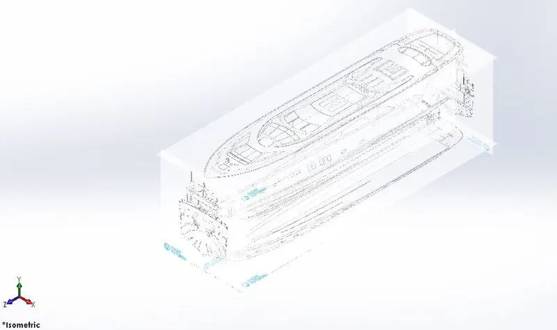
DESCRIPTION OF THE PARTS AND FEATURES USED
1.RADAR
Radar (radio detection and ranging) is a detection system that uses radio waves to determine the distance (ranging), angle, and radial velocity of objects
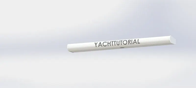
FEATURES USED:
- Boss Extrude
- Cut Extrude
- Fillet
- Sketch Pattern
- Split Line
- Mirror
2.PROPELLER
A propeller (colloquially often called a screw if on a ship or an airscrew if on an aircraft) is a device with a rotating hub and radiating blades that are set at a pitch to form a helical spiral which, when rotated, exerts linear thrust upon a working fluid such as water or air.
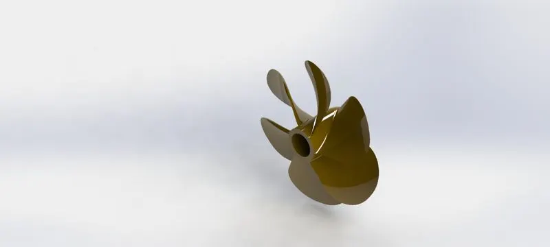
FEATURES USED:
- Cut Extrude
- Revolve
- Circular Pattern
- Loft
- Fillet
- Plane
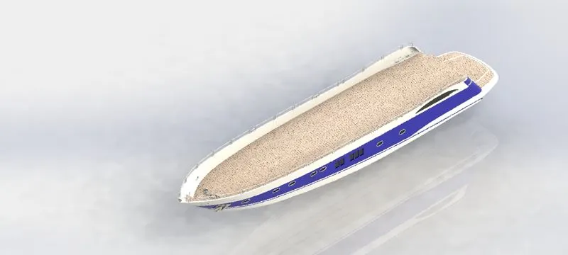
3.HULL
Hull is the watertight body of a ship, boat, or flying boat. The hull may open at the top (such as a dinghy), or it may be fully or partially covered with a deck. Atop the deck may be a deckhouse and other superstructures, such as a funnel, derrick, or mast.
FEATURES USED:
- Surface Loft
- Surface Fill
- Surface Knit
- Surface Extrude
- Surface Fill
- Surface Trim
- Cut Extrude
- Fillet
- Boss Extrude
- Chamfer
- Sweep
- Revolve
- LPattern
- Split Line
- Mirror
- Plane
- Projected Curve
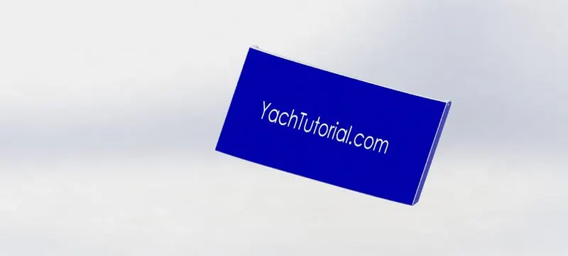
4.GARAGE DOOR
A garage door is a large door on a garage that opens either manually or by an electric motor.
FEATURES USED:
- Cut Extrude
- Shell
- Fillet
- Mirror
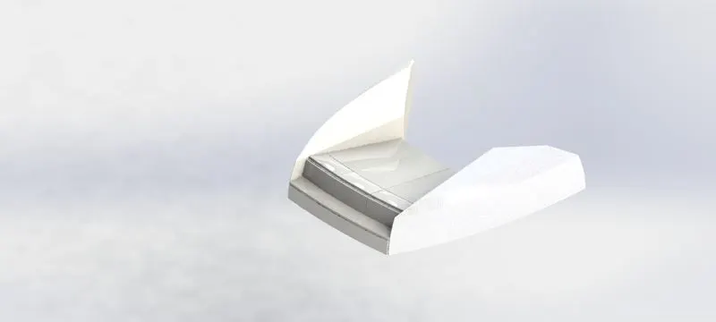
5.FRONT SEAT
A seat at the front of a vehicle, especially the one next to the driver
FEATURES USED:
- Surface Loft
- Surface Fill
- Surface Knit
- Surface Extrude
- Surface Trim
- Cut Extrude
- Fillet
- Boss Extrude
- Chamfer
- Surface Sweep
- Revolve
- Mirror
- Dome
- Plane
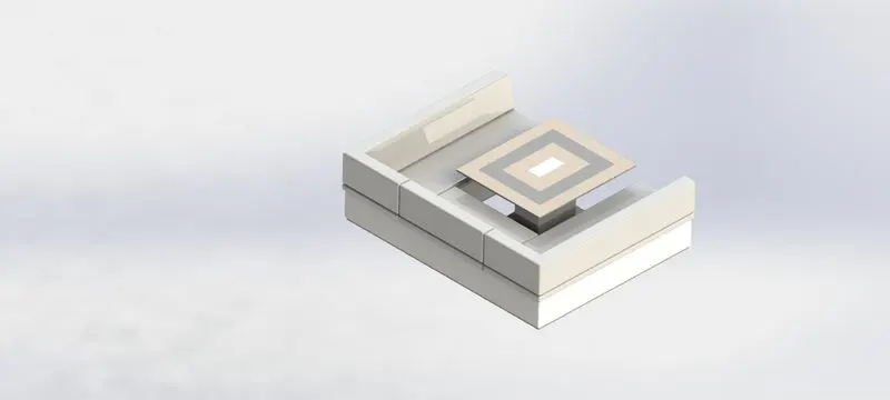
6.MIDDLE SEAT
The part of a chair or other piece of furniture that a person sits.
FEATURES USED:
- Boss Extrude
- Fillet
- Mirror
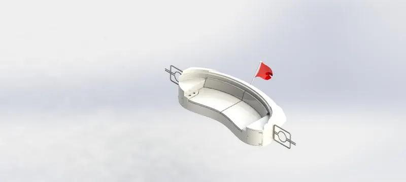
7.REAR SEAT
The part of a chair or other piece of furniture on the back side of the yacht that a person sits.
FEATURES USED:
- Surface Loft
- Surface Fill
- Surface Knit
- Surface Extrude
- Surface Fill
- Surface Trim
- Cut Extrude
- Fillet
- Boss Extrude
- Chamfer
- Surface Sweep
- Revolve
- Mirror
- Sweep
- Plane
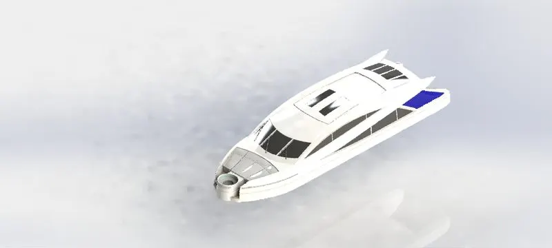
8.SUPERSTRUCTURE
A superstructure is an upward extension of an existing structure above a baseline.
FEATURES USED:
- Surface Loft
- Surface Fill
- Surface Knit
- Surface Extrude
- Surface Fill
- Surface Trim
- Cut Extrude
- Fillet
- Boss Extrude
- Chamfer
- Surface Sweep
- Revolve
- Mirror
- Sweep
- Dome
- Split Line
- Plane
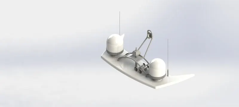
9. RADARMAST
Radarmast are electronic navigation instruments that use a rotating antenna to sweep a narrow beam of microwaves around the water surface surrounding the ship to the horizon, detecting targets by microwaves reflected from them, generating a picture of the ship's surroundings on a display screen.
FEATURES USED:
- Cut Extrude
- Fillet
- Boss Extrude
- Chamfer
- Revolve
- Mirror
- Sweep
- Plane
ASSEMBLY OF YACHT
MAIN ASSEMBLY
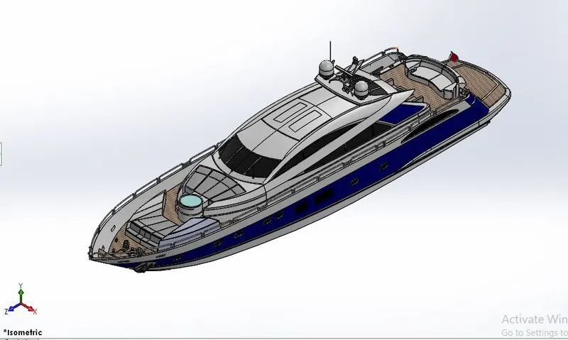
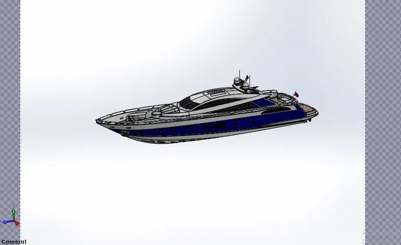
- The Hull part is inserted intially in the assembly by using insert parts in the option.Hull is fixed in the assembly environment.
- After that all the other parts of Yacht are inserted into the assembly and give mate conditions.
Camera Setup View
FEATURES USED TO ASSEMBLE YACHT:
- Mates
- Insert Parts
Mates
Mates creates geometric relationships between assembly components.
Insert Parts
Insert Parts is used to insert other components which is needed to be mated with the fixed component.
RENDERING
- Rendering or image synthesis is the process of generating a photorealistic or non-photorealistic image from a 2D or 3D model by means of a computer program
- Rendering are two types
- Photo view360
- Solid-Works Visualize
Photo view360
- PhotoView 360 is a SOLIDWORKS add-in that produces photo-realistic renderings of SOLIDWORKS models. The rendered image incorporates the appearances, lighting, scene, and decals included with the model.
Solid-Works Visualize
- SOLIDWORKS Visualize allows you to leverage your 3D CAD data to create photo-quality content in the fastest and easiest way you can–from images to animations, interactive web content, and immersive Virtual Reality.
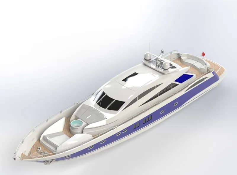
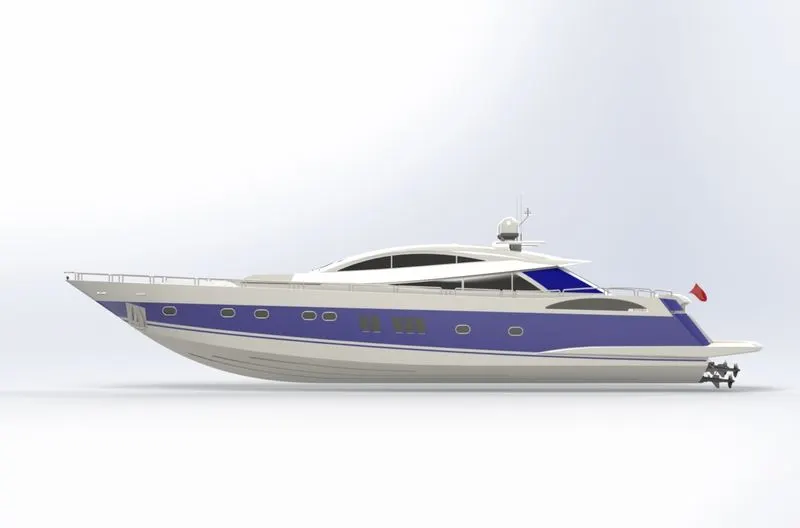
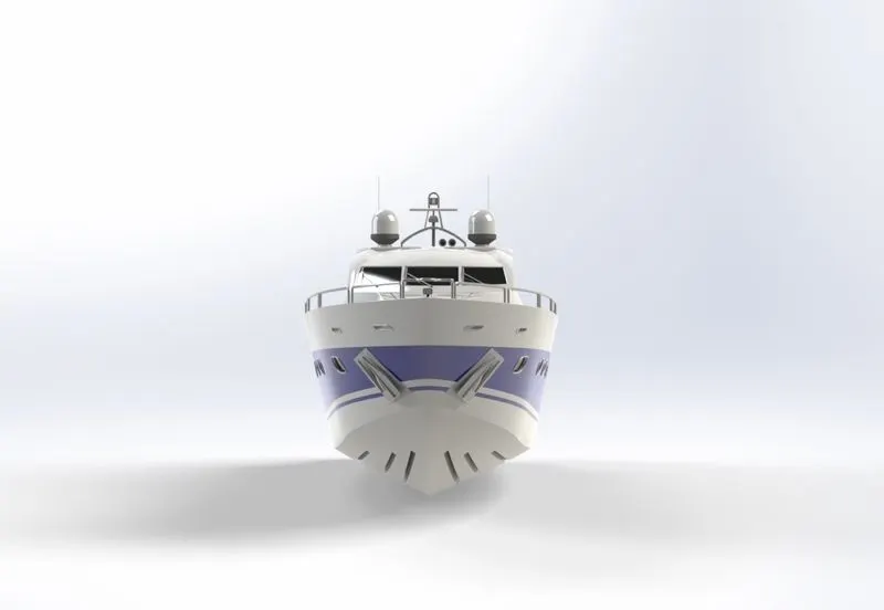
- The photo-realistic is rendered into realistic images with different views.
- PhotoView 360 and SOLIDWORKS Visualize are used for rendering the assembled model.
CONCLUSION
- After modeling the parts of Yacht i have learned more about the tools and features are used in solidworks.
- Assembled the parts of Yacht .
- The photo-realistic image was rendered by using Photo-view360 and Solidworks Visualise.