Photo Realistic Rendering
MODELING AND RENDERING OF AMERICAN CHOPPER USING SOLIDWORKS
OBJECTIVE:
- The main objective of this project is to learn SOLIDWORKS by modeling different parts of American chopper.
- The exploration of tools that are used for the modeling Americian chopper in Solid works.
- To assemble the different parts modeled for the American chopper.
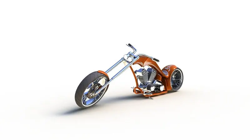
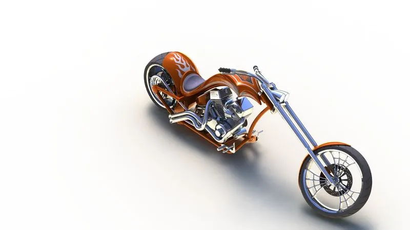
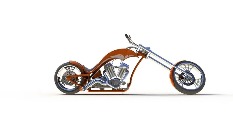
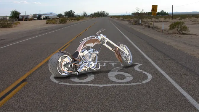
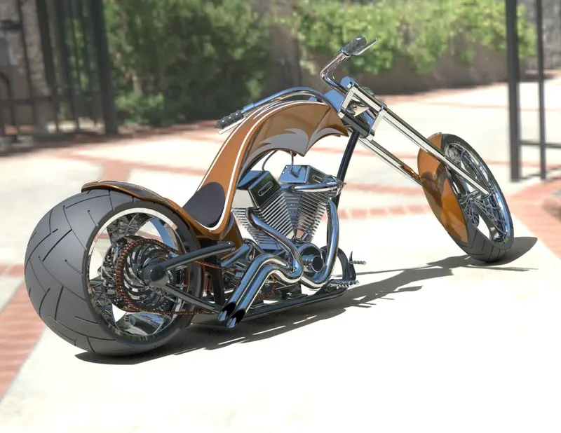
- To create a photo-realistic view of the chopper by rendering the model using SOLIDWORKS Photo View360 and SOLIDWORKS Visualize.
INDRODUCTION
The SOLIDWORKS CAD software is a mechanical design automation application that lets designers quickly sketch out ideas, experiment with features and dimensions, and produce models and detailed drawings.By using Solidworks the designing the parts of an American chopper to the final rendering done by the assembly of parts.
METHODOLOGY
The Design Methodology is explained by a flowchart given below.
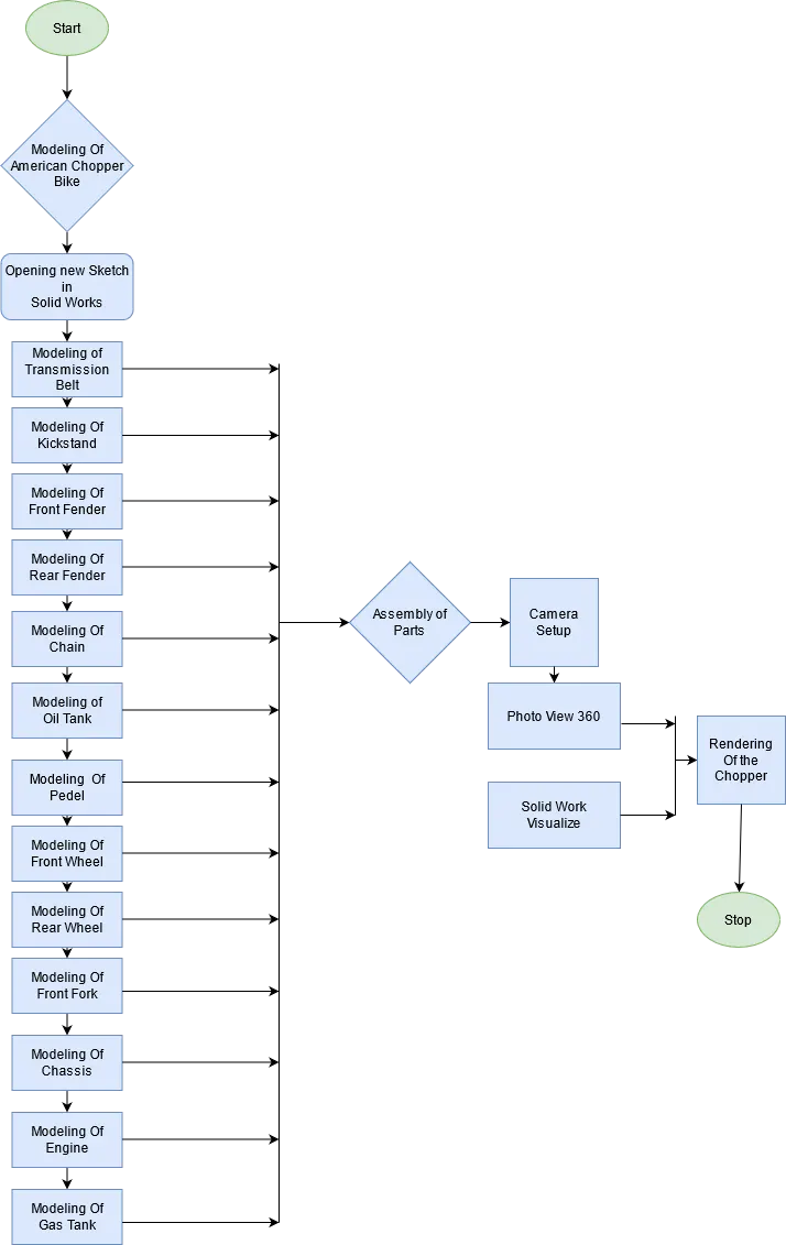
DESCRIPTION OF FEATURES:
SKETCH
- Sketch is the two dimensional representation of the model with respect to the plane/view from the outside of the model.Lines,Arcs,Spline,Circles,Rectangles are available in the sketch known as Entitles in Solid works
OFFSET
- The offset entities tool allows us to create an offset of one or more sketch entities or using model edges or model faces
EXTRUDE BOSS/BASS
- An Extrude Boss/Base feature will allow you to take a 2D sketch and add thickness to it in the third dimension.
EXTRUDE CUT
- Extruded cut feature removes material from the part. The End Condition, Draft, and Thin Feature options are same as described in Extruded Boss/Base.
FILLET
- Fillet/Round creates a rounded internal or external face on the part. You can fillet all edges of a face, selected sets of faces, selected edges, or edge loops.
TRIM ENTITIES
- Select the trim based on the entities you want to trim or extend.Power trim is to trim the sketchs are in 2D on 3D planes.
LOFT BOSS/BASS
- Loft creates a feature by making transitions between profiles. A loft can be a base, boss, cut, or surface. You create a loft using two or more profiles. Only the first, last, or first and last profiles can be points.
DOME
- Select one or more planar or non-planar faces.Apply domes to faces whose centroid lies outside the face.This allows to apply domes to irregularly shaped contours.
SPLIT
- It is used to split one or more solid or surface bodies. To split a surface, the Trimming Surface must extend past the boundaries of the surface to split.
REVOLVE
- Revolves add or remove material by revolving one or more profiles around a centerline. You can create revolved boss/bases, revolved cuts, or revolved surfaces. The revolve feature can be a solid, a thin feature, or a surface.
DYNAMIC MIRROR
- Dynamic Mirror allows the user to mirror a sketch about a line while the user is creating their sketch. Depending on design intent this tool can save an immense amount of time.
COMBINE
- The common function allows you to add two bodies together, and keep the area that is common to them. To use this feature, we will select the common button, and then under Bodies to Combine, select the two bodies.
CHAMFER
- Chamfer tool creates a beveled feature on selected edges, faces, or a vertex. To create a chamfer
SHEEL
- The shell tool hollows out a part, leaves open the faces you select, and creates thin-walled features on the remaining faces. If you do not select any face on the model, you can shell a solid part, creating a closed, hollow model. You can also shell a model using multiple thicknesses.
LINEAR PATTERN
- The Linear Pattern Command is used to drive features, faces, or bodies in a linear direction.It is used to creat different number of instances required to create pattern linearly.
CIRCULAR PATTERN
The circular bobies/features are used to creat different number of instances required to create pattern circularly.
SURFACE MODELING
- Surface modeling gives you the ability to build out a visual representation of an object's exterior and its contours. In other words, it's a surface.
FILLED SURFACE
- The Filled Surface feature constructs a surface patch with any number of sides, within a boundary defined by existing sketches or curves
LOFTED SURFACE
- Loft Surfaces are surfaces generated by multiple 3D Curves or existing edges creating a smooth tangency between the selected curves.
SWEPT SURFACE
- Swept surfaces are surfaces that are generated from the section curve positioned along a path.
SURFACE TRIM
- Surface Trim is used to cut away material from the a surface.
SURFACE KNIT
- Surface Knit is used to knit the two free edges/open edges of the surfaces together.Also it reduced the gap between the two edges of the surfaces.
EXTEND SURFACE
- Extend Surface is used to extend the surface which is already created.The surface can be extend in different options.
DESCRIPTION OF THE PARTS AND FEATURES USED
- TRANSMISSION BELT
Transmission Belt is a loop of flexible material used to link two or more rotating shafts mechanically, most often parallel. Belts may be used as a source of motion, to transmit power efficiently or to track relative movement.
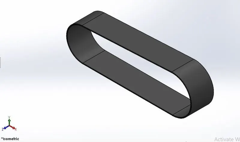
FEATURES USED:
- Boss Extrude
- Fillet
2.KICKSTAND
Kickstand is usually a piece of metal that flips down from the frame and makes contact with the ground. It is generally located in the middle of the bike or towards the rear
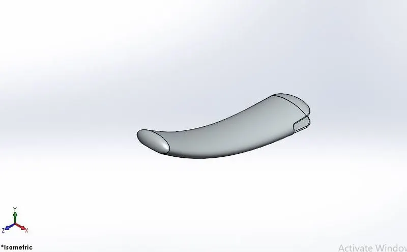
FEATURES USED:
- Loft
- Dome
- Cut Extrude
- Split
- Boss Extrude
- Fillet
3.FRONT FENDER
Fender is the American English term for the part of an automobile, motorcycle or other vehicle body that frames a wheel well (the fender underside).
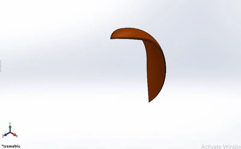
FEATURES USED:
- Revolved Boss
- Split
- Fillet
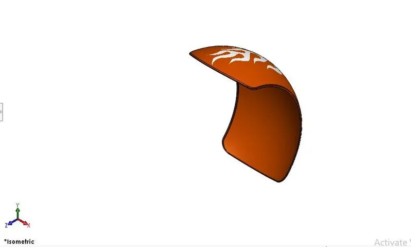
4.REAR FENDER
Fender is the American English term for the part of an automobile, motorcycle or other vehicle body that frames a wheel well (the fender underside).It is used to sand,mud,rocks,liquid into the rotating tire.
FEATURES USED:
- Revolved Boss
- Split
- Fillet
- Shell
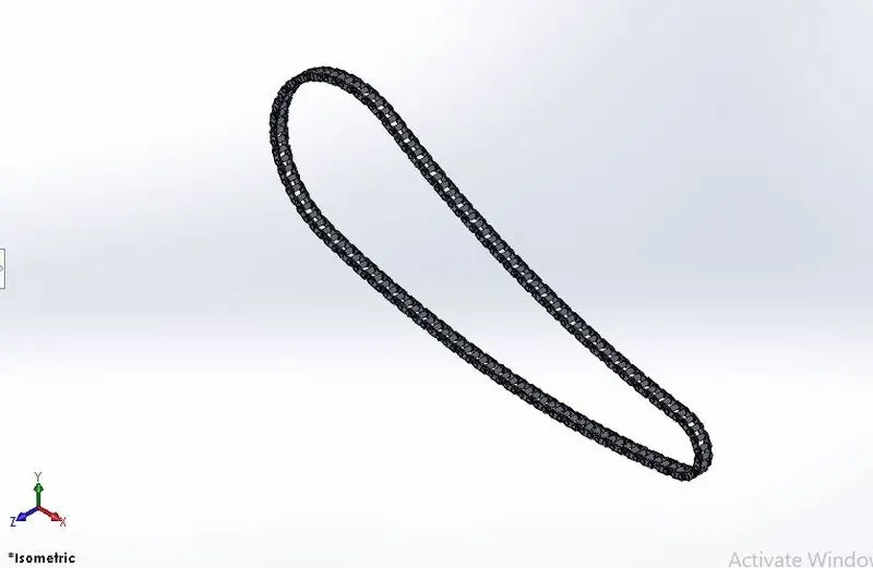
5.CHAIN
Chains are part of the drive train to transmit the motor power to the back wheel.
FEATURES USED:
- Extrude Boss
- Fillet
- Projecting Curve
- Curve Pattern
- Mirror
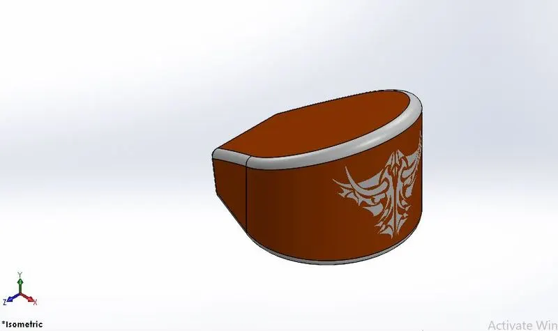
6.OIL TANK
A oil tank has the purpose of storing lubrating oil to lubricate the engine parts to aviod wear and tear due to extreme heating.
FEATURES USED:
- Extrude Boss
- Fillet
- Shell
- Combine
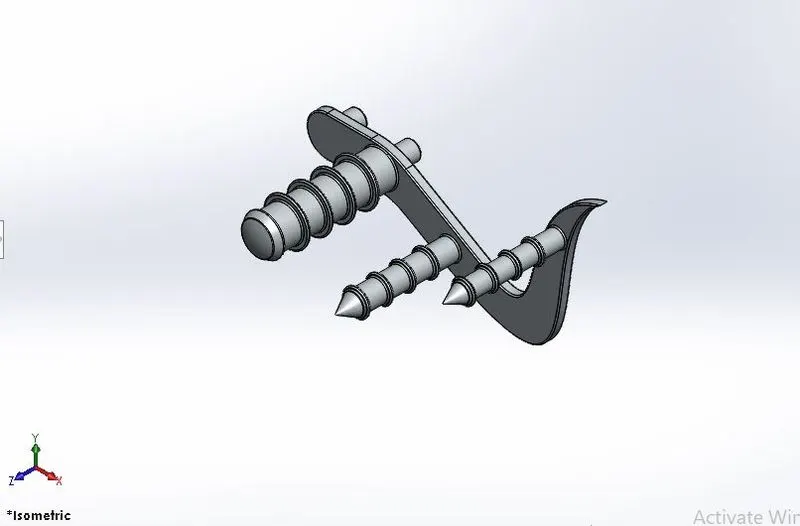
7.PEDAL
The function of the pedal is to shift the gear to get the desire speed from the engine and also apply the break.
FEATURES USED:
- Extrude Boss
- Fillet
- Revolve Boss
- Dome
- Chamfer
- Linear Pattern
8.FRONT WHEEL
Wheel is a circular block of a hard and durable material at whose center has been bored a hole through which is placed an axle bearing about which the wheel rotates.
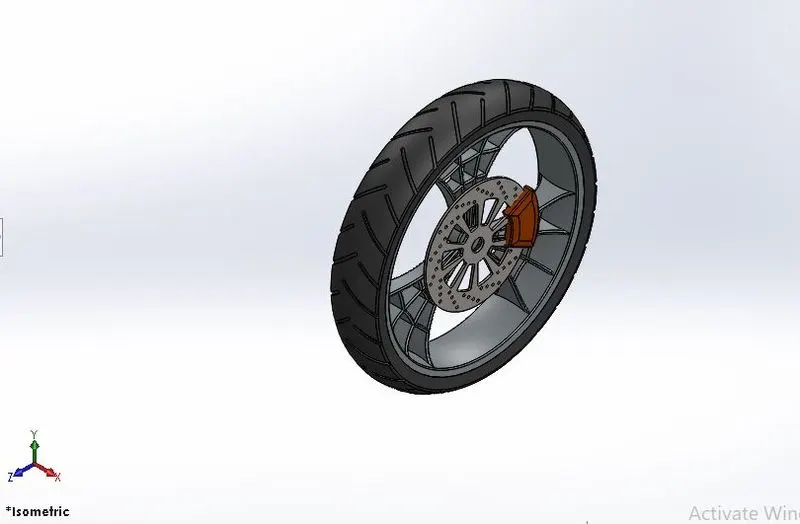
FEATURES USED:
- Extrude Boss
- Cut Extrude
- Revolve Cut
- Circular Pattern
- Combine
- Fillet
- Chamfer
9.REAR WHEEL
Wheel is a circular block of a hard and durable material at whose center has been bored a hole through which is placed an axle bearing about which the wheel rotates when torque is applied to the wheel about its axis.
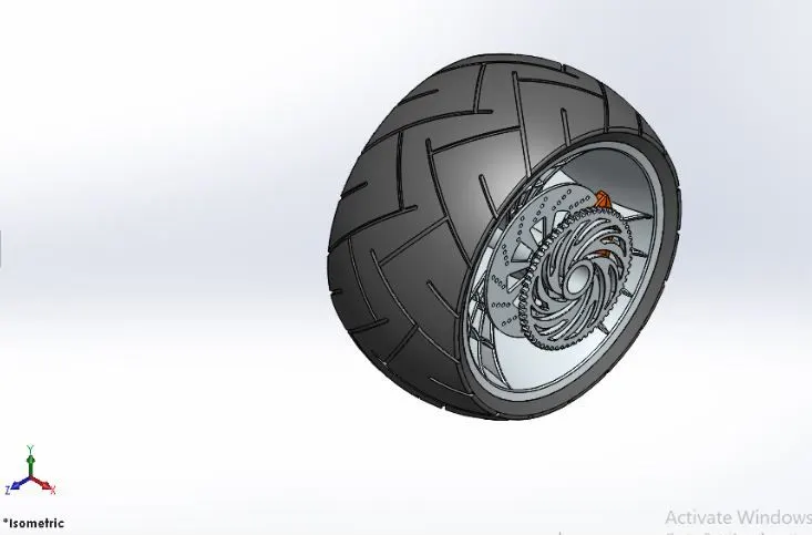
FEATURES USED:
- Extrude Boss
- Revolve Boss
- Fillet
- Extrude Cut
- Dome
- Revolve Cut
- Swept Curve
- Project Curve
- Mirror
- Combine
10.FRONT FORK
A fork typically consists of two blades which are joined at the top by a fork crown. The crown is often at the front. Most suspension forks have an arch connecting the two side of the lowers (the part connected to the axle).
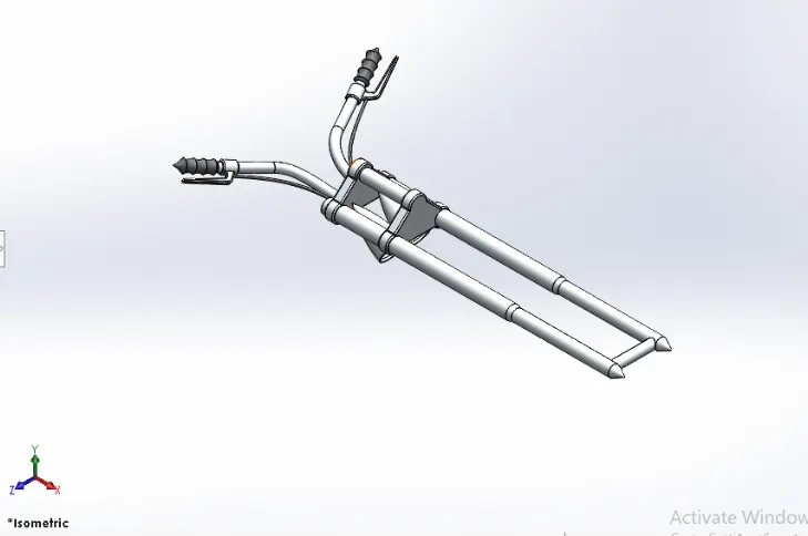
FEATURES USED:
- Extrude Boss
- Revolved Boss
- Fillet
- Extrude Cut
- Dome
- Revolved Cut
- Swept Boss
- Project Curve
- Mirror
- Combine
11.CHASSIS
Chassis is the main support structure of the vehicle which is also known as 'Frame'. It bears all the stresses on the vehicle in both static and dynamic conditions.
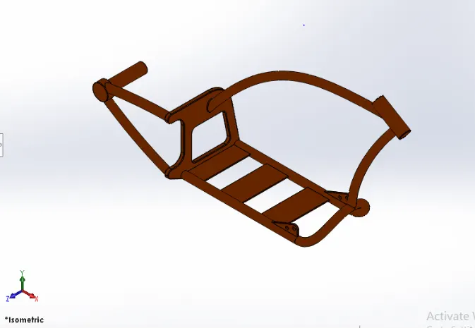
FEATURES USED:
- Swept Boss
- Project Curve
- Mirror
- Extrude Boss
- Fillet
- Extrude Cut
- Dome
- Combine
- Chamfer
- Split
- Revolved Boss
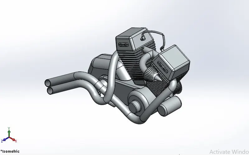
12.ENGINE
An engine or motor is a machine designed to convert one form of energy into mechanical energy.
FEATURES USED:
- Swept Boss
- Project Curve
- Mirror
- Extrude Boss
- Fillet
- Extrude Cut
- Dome
- Chamfer
- Split
- Revolved Boss
- Linear Pattern
- Circular pattern
- Composite Curve
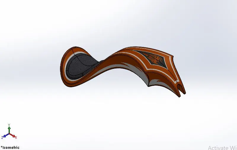
13.GAS TANK
A Gas tank (also called a petrol tank )is a safe container for flammable fluids. Though any storage tank for fuel may be so called, the term is typically applied to part of an engine system in which the fuel is stored and propelled (fuel pump) or released (pressurized gas) into an engine.
FEATURES USED:
- Surface Loft
- Surface Knit
- Projected Curve
- Fillet
- Swept Surface
- Split
- Mirror
- Swept Cut
- Plane
ASSEMBLY OF AMERICAN CHOPPER
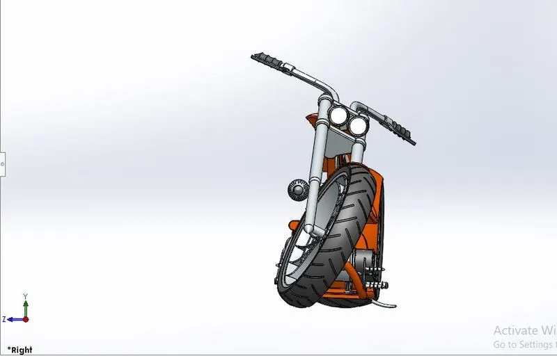
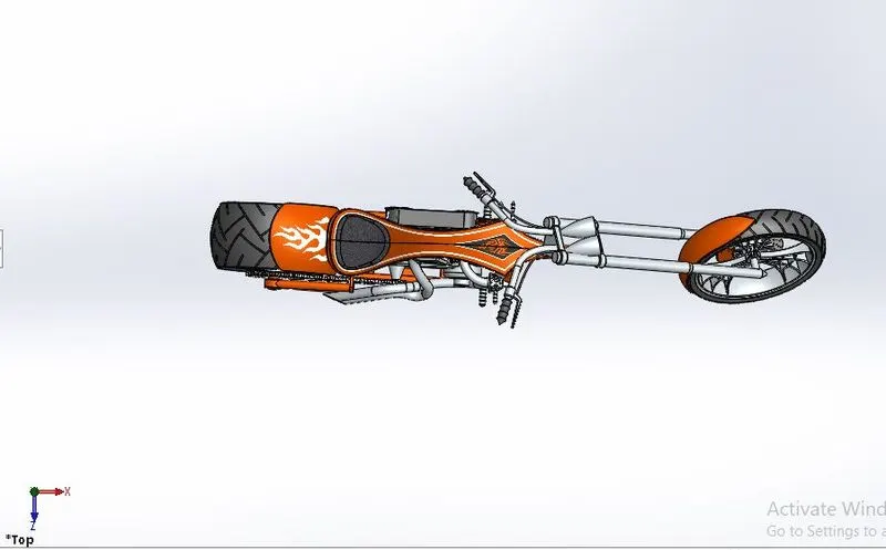
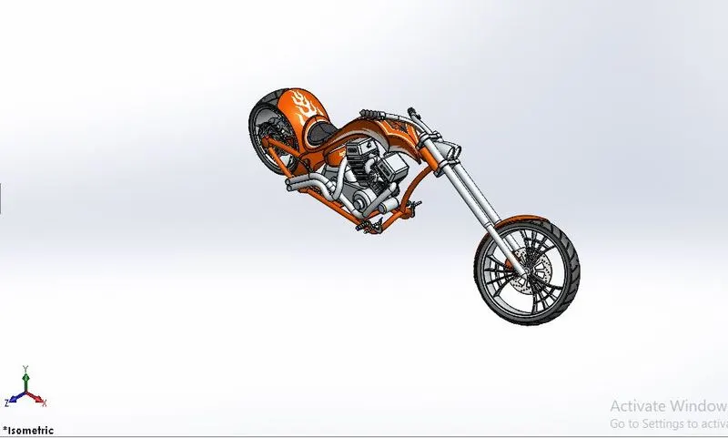
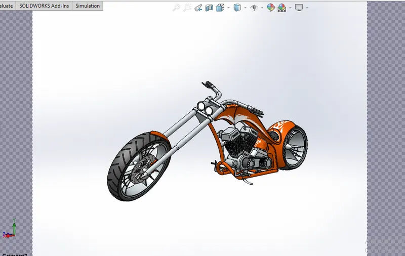
MAIN ASSEMBLY
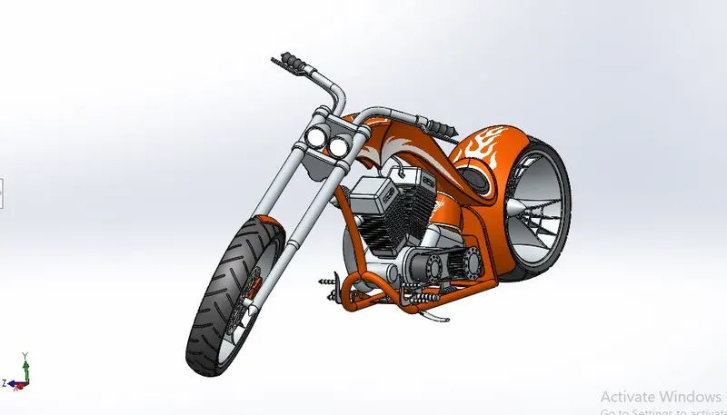
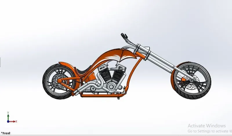
- The Chassis part is inserted intially in the assembly by using insert parts in the option.Chassis is fixed in the assembly environment.
- After that all the other parts of chopper are inserted into the assembly and give mate conditions.
Front View Side View
Top View Isometric View
Camera Setup View
FEATURES USED TO ASSEMBLE AMERICAN CHOPPER:
- Mates
- Insert Parts
Mates
Mates creates geometric relationships between assembly components.
Insert Parts
Insert Parts is used to insert other components which is needed to be mated with the fixed component(Chassis).
RENDERING
- Rendering or image synthesis is the process of generating a photorealistic or non-photorealistic image from a 2D or 3D model by means of a computer program
- Rendering are two types
- Photo view360
- Solid-Works Visualize
Photo view360
- PhotoView 360 is a SOLIDWORKS add-in that produces photo-realistic renderings of SOLIDWORKS models. The rendered image incorporates the appearances, lighting, scene, and decals included with the model.
Solid-Works Visualize
- SOLIDWORKS Visualize allows you to leverage your 3D CAD data to create photo-quality content in the fastest and easiest way you can–from images to animations, interactive web content, and immersive Virtual Reality.
- The photo-realistic is rendered into realistic images with different views.
- PhotoView 360 and SOLIDWORKS Visualize are used for rendering the assembled model.
CONCLUSION
- After modeling the parts of American chopper i have learned about the tools and features are used in solidworks.
- Assembled the parts of American chopper .
- The photo-realistic image was rendered by using Photo-view360 and Solidworks Visualise.
LINK OF THE ZIP FILE:
https://drive.google.com/file/d/19feNl0pHiWpCr90bRpAhd6dwa9oCRAmc/view?usp=sharing