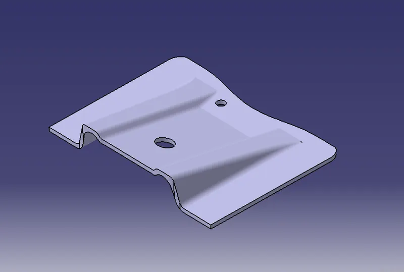
Week 8 - Challenge 1 - Base Bracket Design
REPORT
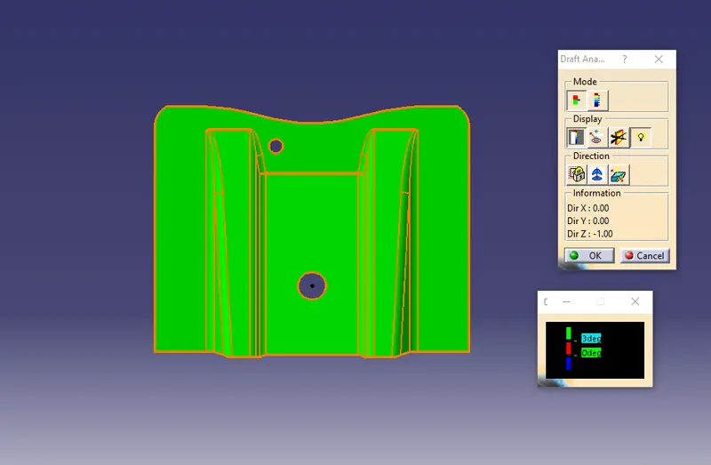
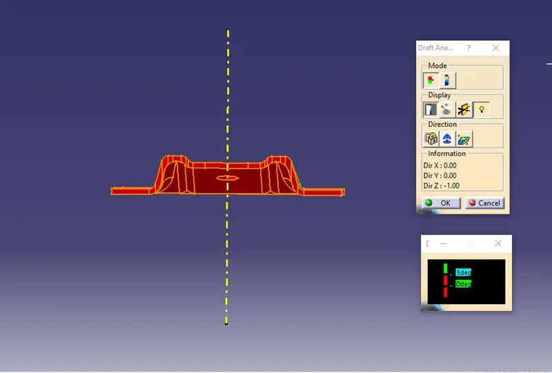
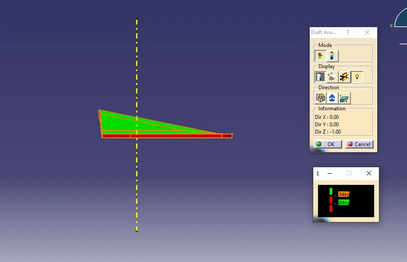
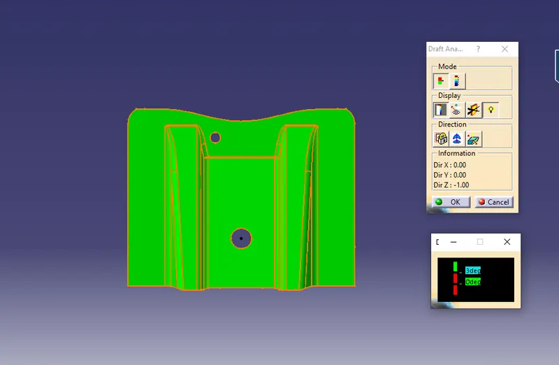
Draft Analysis
The Draft Analysis command enables you to detect if the part you drafted will be easily removed. This type of analysis is performed based on color ranges identifying zones on the analyzed element where the deviation from the draft direction at any point, corresponds to specified values.
Class A surface
It provides information about the aesthetic features of a component. The product designer starts development of design models from class A surface.
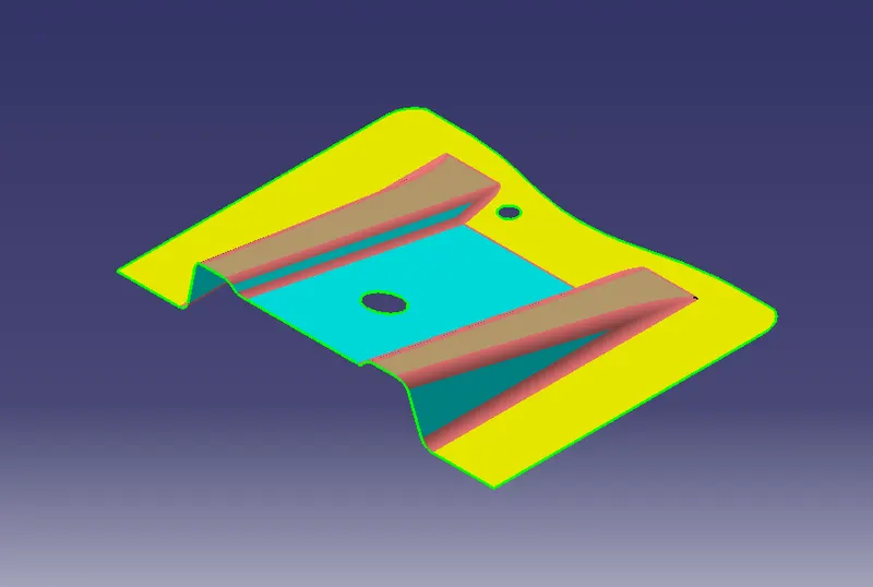
Class B surface
It provides information about the engineering features of a component. This surface is created by offsetting it from class A surface.
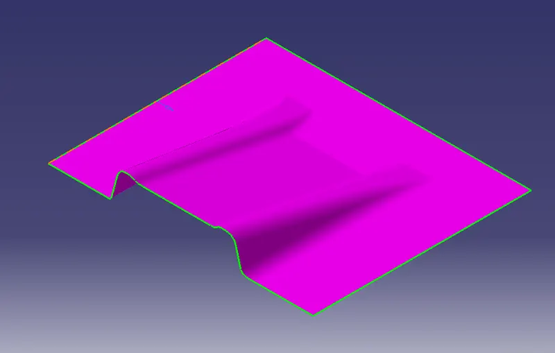
Class C surface
It is a surface that connects surface A and surface B along tooling direction.
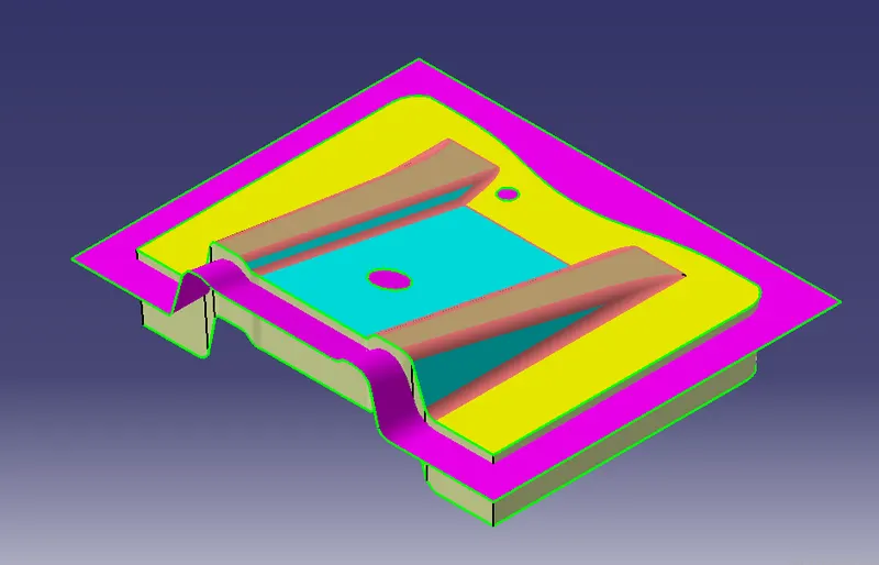
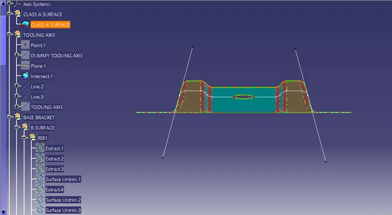
Tooling Axis
It is direction along which the core and cavity open and close. Draft is also given along the tooling axis.
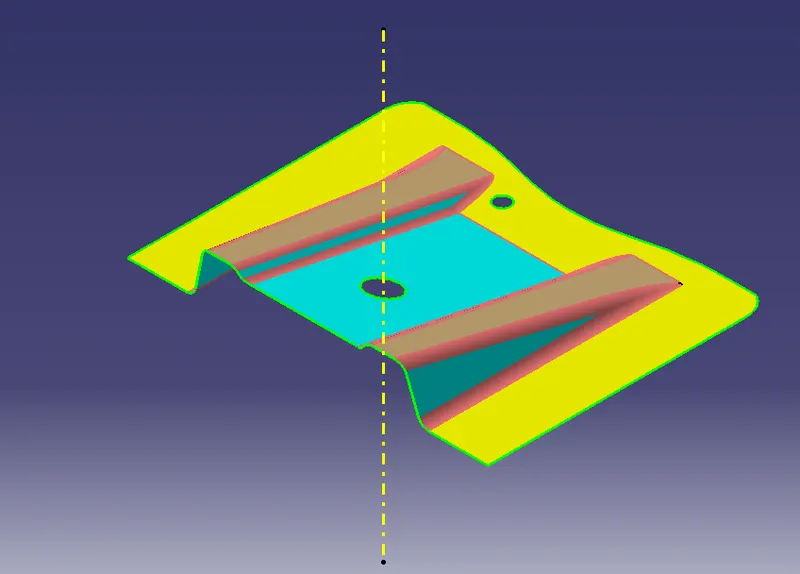
Draft Analysis Of Class A Surface
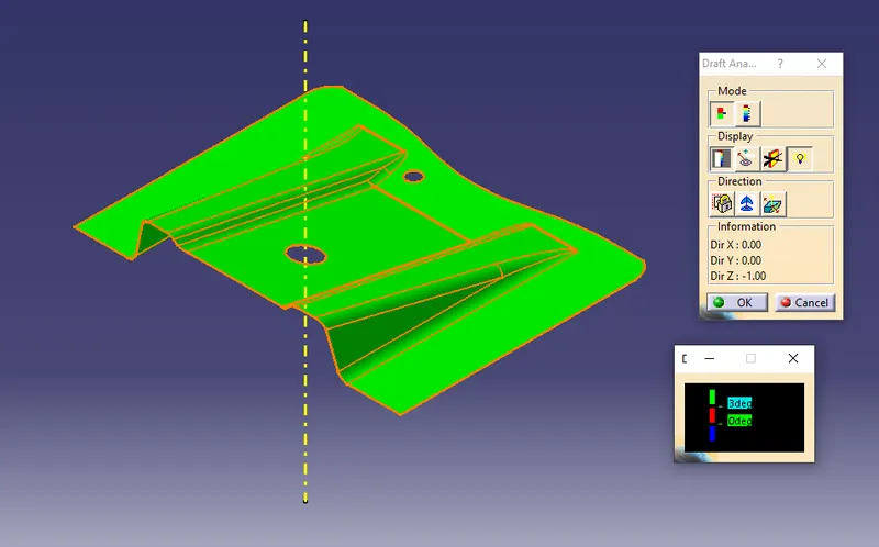
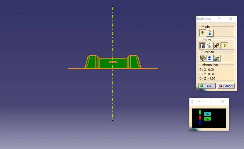
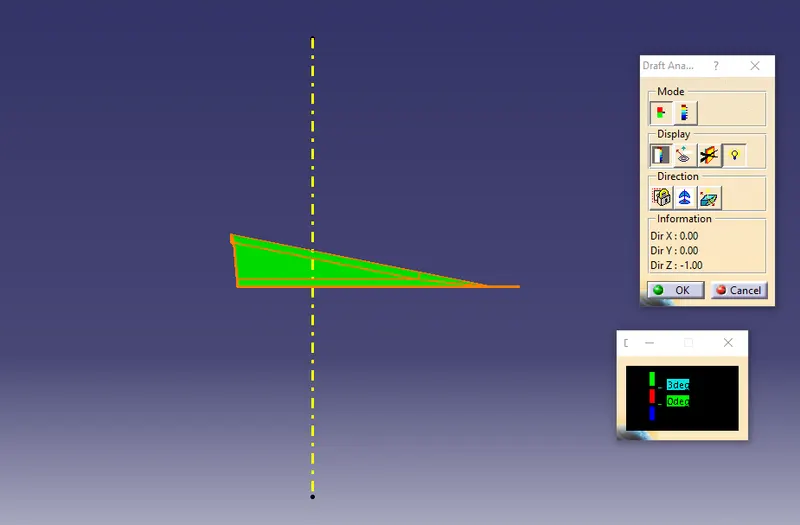
Creating tooling axis:
1. Creating tooling lines.
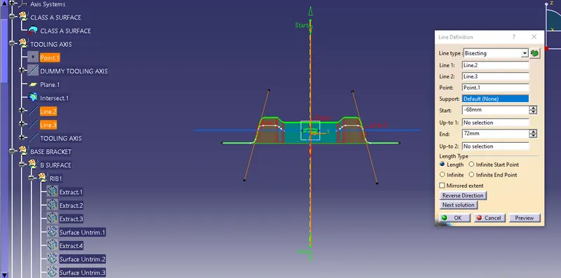
2. Creating a line with the help of 'bisecting' in line toolbar.
Draft Analysis On Final Component
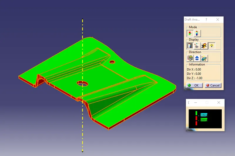
VIEWS
Front View
Side View
Top View
Isometric View
Closed Solid Body