Radar Mast & Final Assembly of Yacht
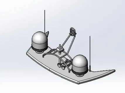
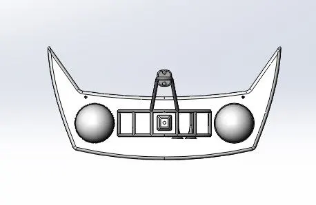
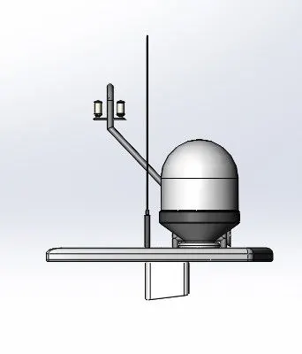
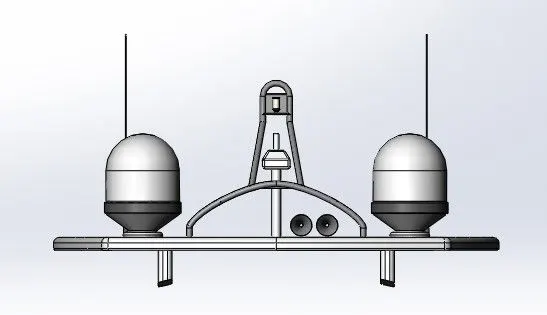
Radar Mast :
Isometric view :
Top view :
Left view :
Front view :
Right view :
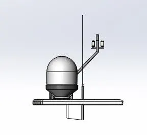
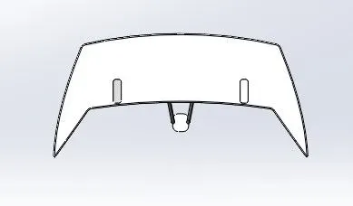
Bottom view :
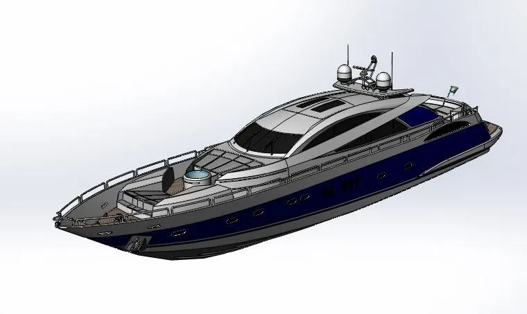
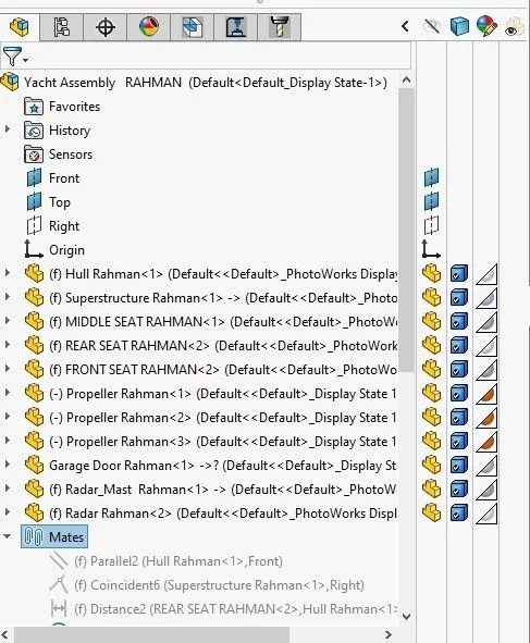
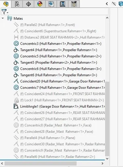
Yacht Assembly
Title of the Project : YACHT MODELLING
Objective :
To model a Yacht using Solid Works Part file assemble all the individual parts using the solidworks assembly file and perform attractive rendering operations using solidworks visualize (or) Photoview 360.
Introduction :
A Yacht is a sail or Power vessel used for pleasure ,cruising or racing .there is no standard definition,so the term applies to such vessels that have a cabin with amenities that accommodate overnight use . to be termed a yacht , as opposed to a boat , such a pleasure vessel is likely to be at least 33 feet (10m) in length and may have been judged to have good aesthetic qualities. Originally , all yachts were made of wood , using a wooden keel and ribs clad planks .These materials were supplanted with iron or steel in steam yachts.in the 1960s fiberglass became a prevalent material . these materials and others continue in use . wheras yachts of 79 feet (24m) and below may constructed of fiberglass ,larger yachts are more likely to be constructed of steel , aluminum or compsite fiber -reinforced plastic.
Design methodology / approach :
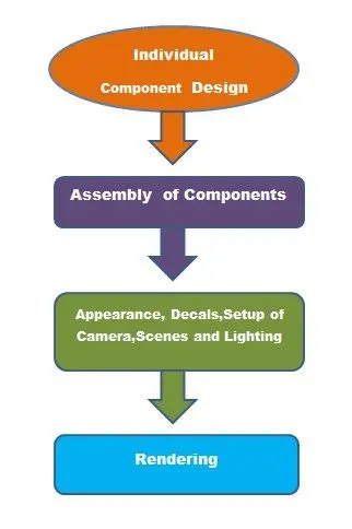
Yatch Modelling Flow :
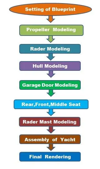
Description :
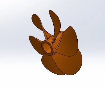
Propeller :
Sketch Tools and Features :
Sketch: To Create required Sketches.
Line: To drawing line and construction lines.
Circle: To draw a circle.
Boss - Revolve : To revove 2d sketch along the reference to obtain solid body.
Fillet :To Convert sharp internal or external edgers into smooth or round edges.
Cut- Extrude: To subtract a solid portion from a solid using 2d sketch.
Circular Pattern : To create a pattern of feature or body along a circular reference.
Surface - Lofe: To create surface along the profiles.
The solid component ,consisting of a hollow cylider of a certain thickness,has fan blades mouted over the outer suface of the cylider a propellor .the main function of the propellor is to exert thrust by rotating of fan blade under the water so that the yacht can move forward.
- It was modeled by using solid features such as revolve Boss/Base ,Extrude cut,etc.
- First a blade is modeled using the lofted Boss/ Base feature Then the blade is mirrored using the circular pattern feature .
- Further,the fillet ferature is used to remove all sharp edges.
- Finally ,appearance is given to the propellor and file is saved.
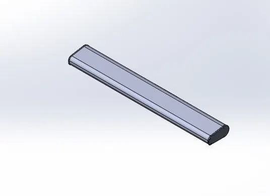
Radar :
Sketch Tools and Features :
Sketch: To Create required Sketches.
Line: To drawing line and construction lines.
Rectangle: This feature allows us creats squares or rectangles.
Circle: To draw a circle.
Boss - Extrude : To Obtain 3d solid from 2d Sketch.
Mirror : To mirror features or sketches along the selected reference.
Fillet :To Convert sharp internal or external edgers into smooth or round edges.
Cut- Extrude: To subtract a solid portion from a solid using 2d sketch.
It is a navigation tool used in yachts.Radio detection and ranging RADER helps ships to detect objects far away by using radio waves . it is very useful in bad weather for navigation. it sends radio waves in all directions and when the signal hits an object then its info is displayed on the screen. hence the pilot can steer away to avoid any collision or accident.
- It was modeled by using solid features such as revolve Boss/Base Extrude cut,etc.
- The fillet feature is used to used to remove all sharp edges.
- As the Radar is symmetric is shape therefore,half part was modeled and other half was mirrored using the mirror feature and both solids were merged in the operation .
- Also the text is added to the radar to give it a realistic look .the text was projected on the surface of the rader using the split line feature.
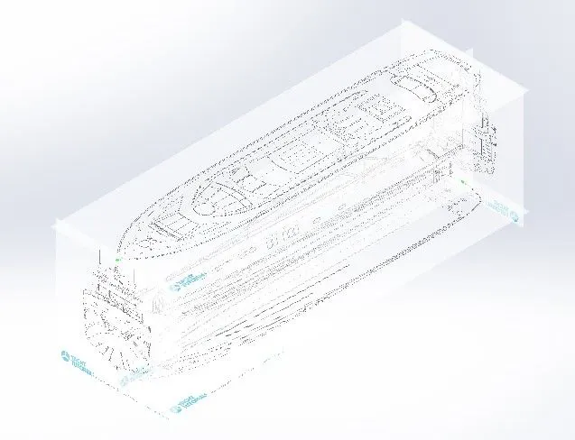
Blueprints :
Sketch Tools and Features :
Sketch: To Create required Sketches.
Sketch Pictures: To insert pictures for reference
Blueprints were imported into Solidworks part by the follwing path tools Sketch Tools - Sketch picture .Then dimension was given to position the blueprints according to the planes .This setup was used to create all the components of the yacht.
Hull_Part :
Sketch Tools and Features :
Sketch: To Create required Sketches.
Line: To drawing line and construction lines.
Circle: To draw a circle.
Boss - Revolve : To revove 2d sketch along the reference to obtain solid body.
Fillet :To Convert sharp internal or external edgers into smooth or round edges.
Cut- Extrude: To subtract a solid portion from a solid using 2d sketch.
Circular Pattern : To create a pattern of feature or body along a circular reference.
Surface - Lofe: To create surface along the profiles.
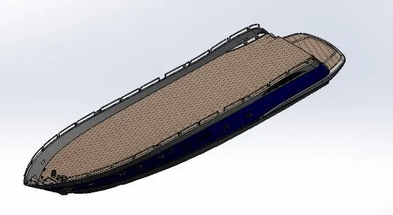
Hull is a bottom floating body of a yacht that meets the water liner below and is open above . surface modeling was used to model hull .i used project curves , surface extrudes, trim surface, lofted surface,knit surface and other surface and solid features to design a yacht from 2D & 3D model first we created blueprints from differnt planes then we created 2D sketches and converted 2D & 3D by using surface features. then we created a solid body from the surface and knitted together the different components of the hull . Only half portion of the hull was modeled and the other half was mirrored using the mirror feature as it is symmetric . fillets were used to eliminate sharp edges and give them an aesthetic appeal .the appearance was given for a realistic look.
Garage Door :
Sketch Tools and Features :
Sketch: To Create required Sketches.
Line: To drawing line and construction lines.
Sheel : To convert solid bodies into shells
Fillet :To Convert sharp internal or external edgers into smooth or round edges.
Cut- Extrude: To subtract a solid portion from a solid using 2d sketch.
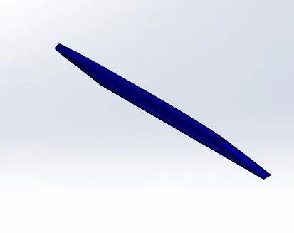
Garage door is a simple skech model which is made by 2D sketches and featuturs like shell cut extrude ,mirror reference plane and fillets ,for getting a text carved on the front side of the garage door ,tool sketch tool is used applied dark blue color for the garage door and white color for the using appearance option
Front Seat :
Sketch Tools and Features :
Sketch: To Create required Sketches.
Line: To drawing line and construction lines.
Circle: To draw a circle.
Boss - Revolve : To revove 2d sketch along the reference to obtain solid body.
Fillet :To Convert sharp internal or external edgers into smooth or round edges.
Cut- Extrude: To subtract a solid portion from a solid using 2d sketch.
Circular Pattern : To create a pattern of feature or body along a circular reference.
Surface - Lofe: To create surface along the profiles.
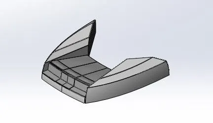
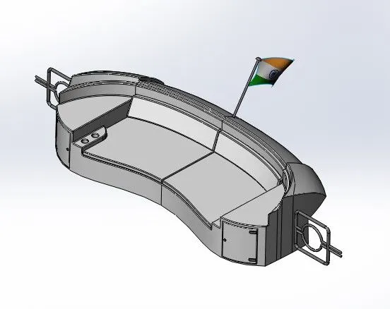
i have desigened the front seat by using features likes Boss extrude, surface extrude, surface cut trim surface , project curve , and other commands in solidworks . first i created a 2D sketch by referring to the blueprints. then i converted it into a solid model by using a knit surface and forming a solid feature.
Middle Seat :
Sketch Tools and Features :
Sketch: To Create required Sketches.
Line: To drawing line and construction lines.
Circle: To draw a circle.
Boss - Revolve : To revove 2d sketch along the reference to obtain solid body.
Fillet :To Convert sharp internal or external edgers into smooth or round edges.
Cut- Extrude: To subtract a solid portion from a solid using 2d sketch.
Circular Pattern : To create a pattern of feature or body along a circular reference.
Surface - Lofe: To create surface along the profiles.
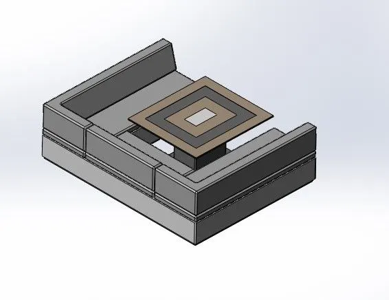
i have designed the front seat by using features likes Boss extrude, surface extrude, surface cut trim surface , project curve and other commands in solidwoks. first i created a 2D sketch by referring to the blueprints. Then i converted it into a solid model by using a knit surface and forming a solid feature. fillets were used to eliminate sharp edges and give them an aesthetic . the appearance was given for a realistic look.
Rear Seat :
Sketch Tools and Features :
Sketch: To Create required Sketches.
Line: To drawing line and construction lines.
Circle: To draw a circle.
Boss - Revolve : To revove 2d sketch along the reference to obtain solid body.
Fillet :To Convert sharp internal or external edgers into smooth or round edges.
Cut- Extrude: To subtract a solid portion from a solid using 2d sketch.
Circular Pattern : To create a pattern of feature or body along a circular reference.
Surface - Lofe: To create surface along the profiles.
i have designed the front seat by using features likes Boss extrude, Surface extrude, surface cut trim surface,project curve , and other commands in Solidwords. First i created a 2D sketch by referring to the blueprints.Then i converted it into a solid model by using a knit surface and forming a solid feature.
Superstructure :
Sketch Tools and Features :
Sketch: To Create required Sketches.
Line: To drawing line and construction lines.
Circle: To draw a circle.
Boss - Revolve : To revove 2d sketch along the reference to obtain solid body.
Fillet :To Convert sharp internal or external edgers into smooth or round edges.
Cut- Extrude: To subtract a solid portion from a solid using 2d sketch.
Circular Pattern : To create a pattern of feature or body along a circular reference.
Surface - Lofe: To create surface along the profiles.
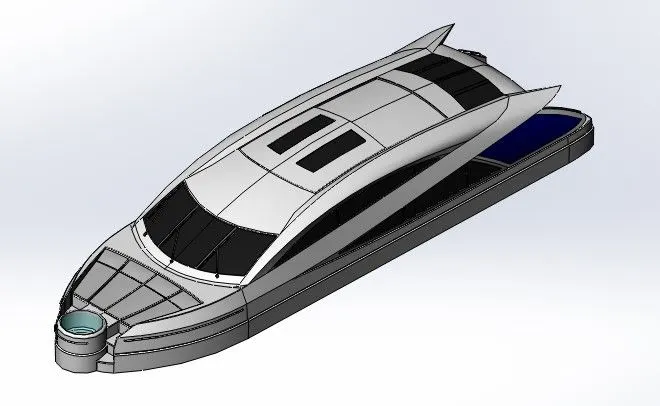
Superstructure is the upper part of the yacht which is attached to the hull and gives a complete look to the yacht. i have designed the superstructure by using the project curve from referring to the blueprints. project curve helps to create a curve in 3D from a 2D sketch .By using surface features ,i created a closed hollow superstructure body .then merged all the surfaces , knitted them and formed a solid superstructure afterward, i had given appearances to different parts of the superstructure.only half portion of the superstructure .afterward, i had given appearances to different parts of the superstructure.only half portion of the superstructure was modeled and the other half was mirrored using the mirror feature as it is symmertric .fillets and chamfers were used to eliminate sharp edges and give them an aesthetic appeal .the appearnce was given for a realistic look.
Radar_Mast :
Sketch Tools and Features :
Sketch: To Create required Sketches.
Line: To drawing line and construction lines.
Circle: To draw a circle.
Boss - Revolve : To revove 2d sketch along the reference to obtain solid body.
Fillet :To Convert sharp internal or external edgers into smooth or round edges.
Cut- Extrude: To subtract a solid portion from a solid using 2d sketch.
Circular Pattern : To create a pattern of feature or body along a circular reference.
Surface - Lofe: To create surface along the profiles.
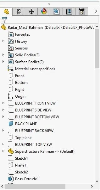
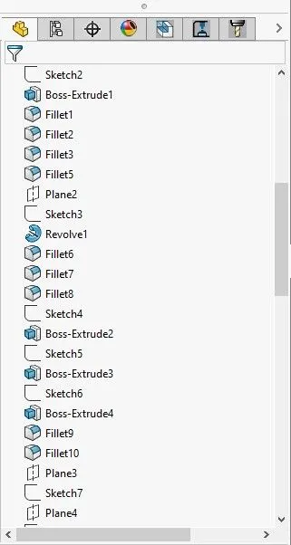
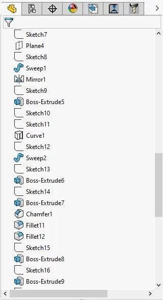
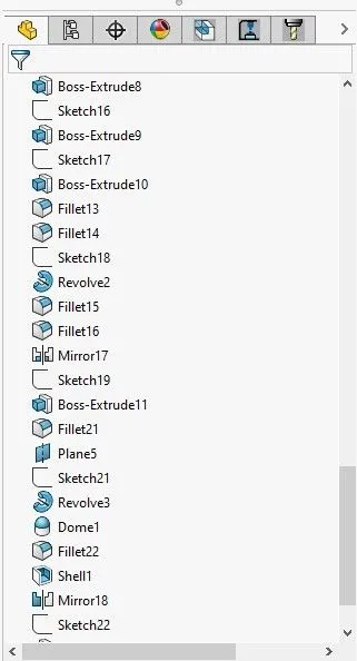
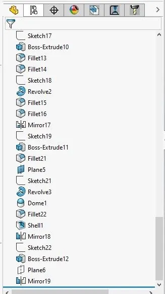
The design starts with outlaying the sketch of the base pedal on the front plane and an extruded boss is created with dimensioned circular holes for the footrest and the pins which are extruded the second time now a sketch is created on the top plane for the footrest which is then revolved to make a 3D image the top of the rest is applid with a dome and the edges and joints are filleted to avoid sharp cuts,the front and the rear extruded cylindrical parts are then chamfered to attain a proper finish and a circular pattern is extruded on each of the front -facing extrudes which are then arranged using linear pattern and fillet is applied to all the edges and the joints of the last pattern.
Assembly Model :
Isometric view :
Top view :
Left view :
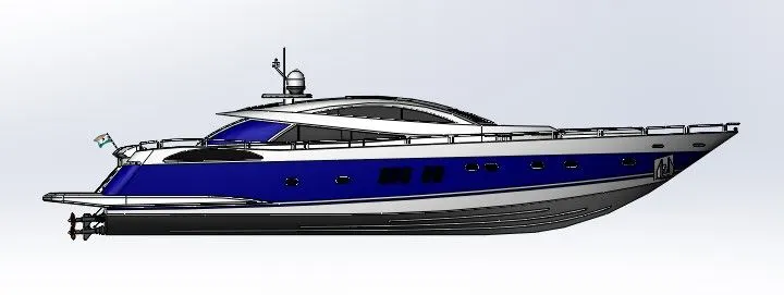
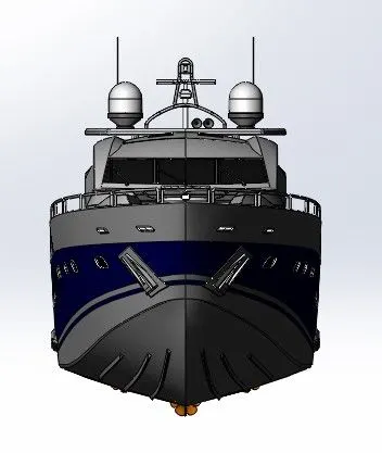
Front view :
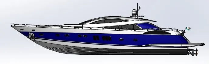
Right view :
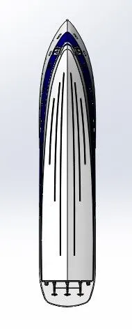
Bottom view :
Camera Setup View :
Rendering Images of Assembly:
Isometric view :
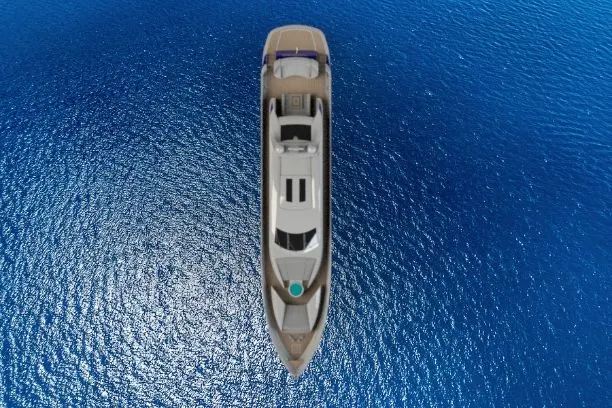
Top view :
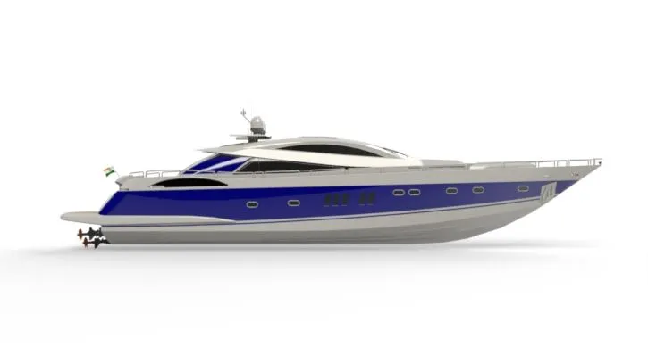
Left view :
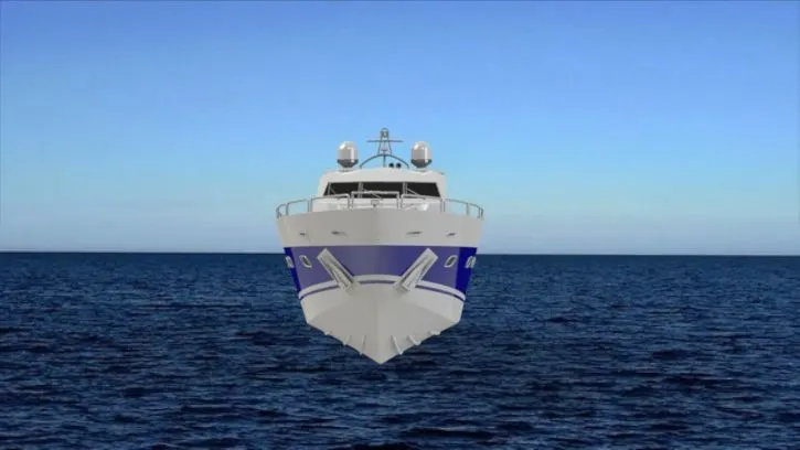
Front view :
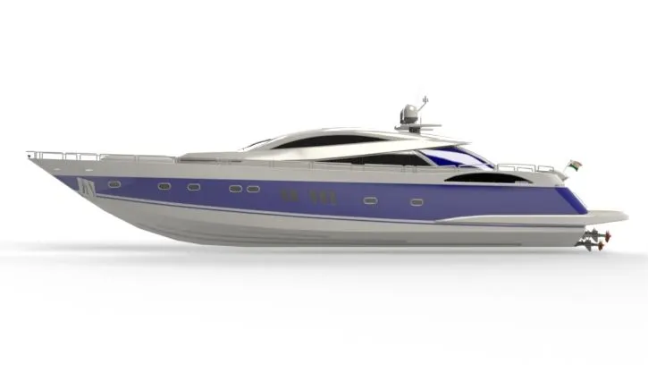
Right view :
Back View :
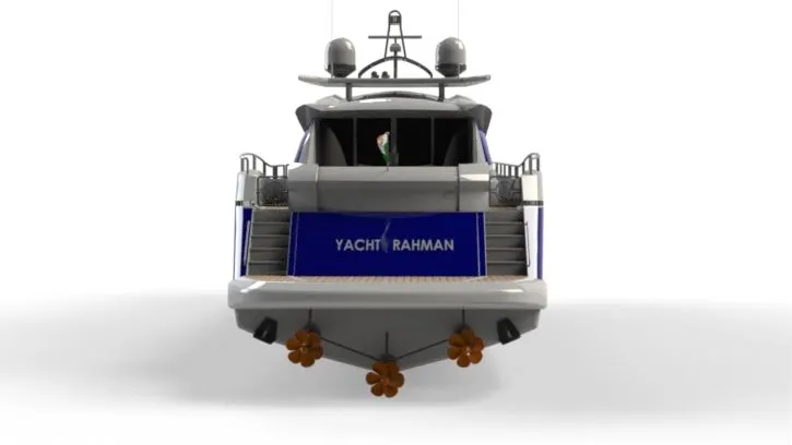
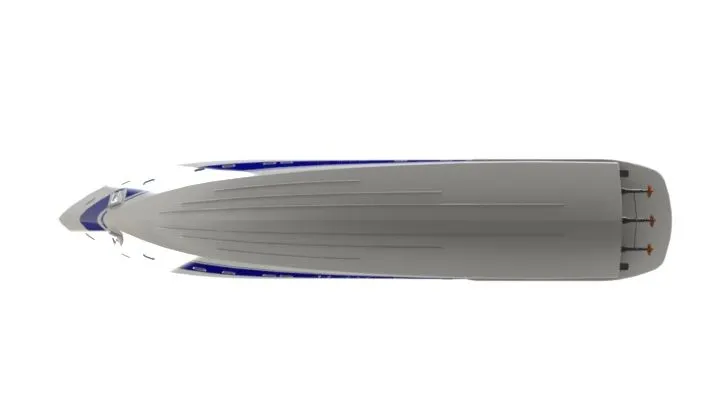
Bottom view :
Camera Setup View :
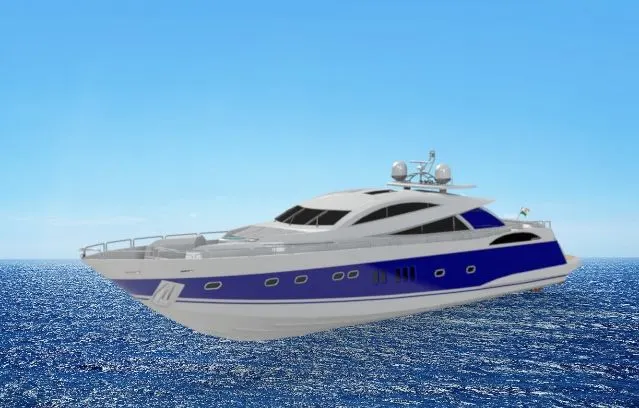
Rendering Images :
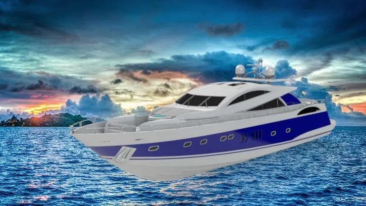
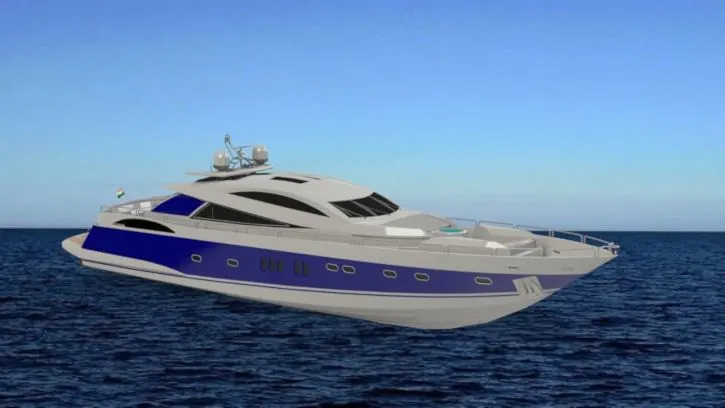
For creating Photo realisic images of the Yacht we renderd the models. The process consists of adding cameras ,lights,environment,scenes and backgrouds. All the while changing of each feature, adjusting thaem to create the perfect appearance setting for our final model rendering.
Rendering of the model is done using below add-ins and software
Photoview 360
Solidworks Visualiza.
Conclusion:
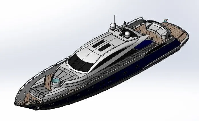
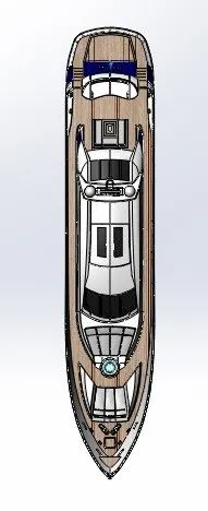
Thus the complete exterior body parts of a Yacht are modelled in solidworks Part file ,assembled in solidworks Assembly file and then the assembly is rendered using SolidWorks Visualize.