Radar Mast & Final Assembly of Yacht
RADARMAST
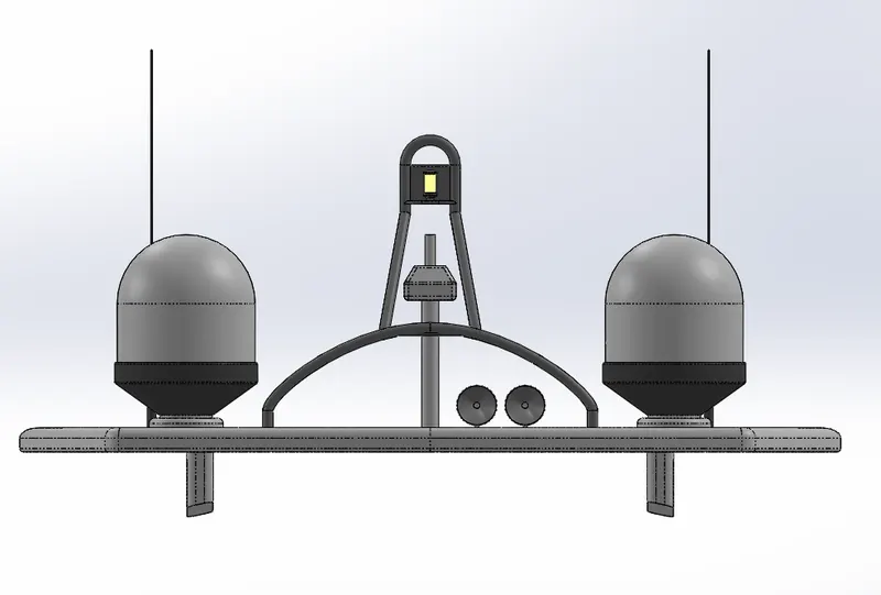
Front View:
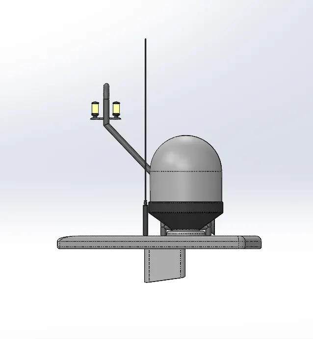
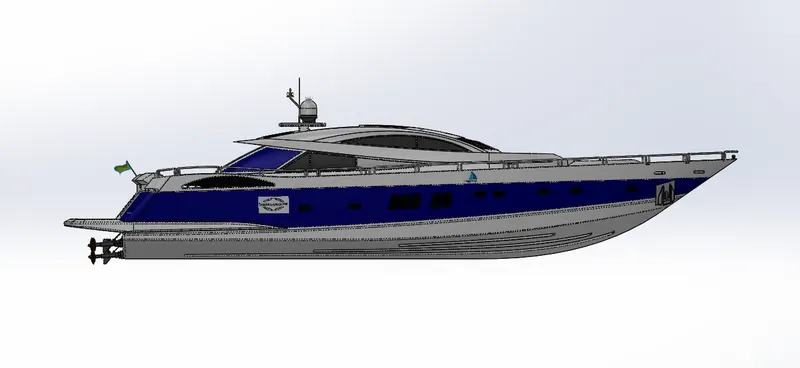
Side View:
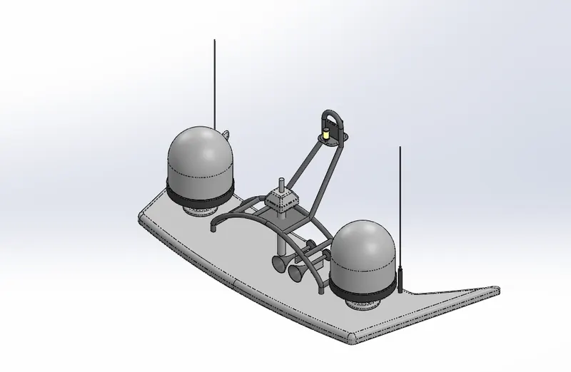
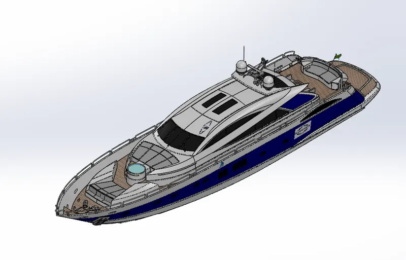
Isometric View:
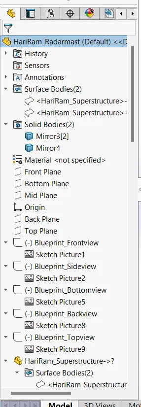
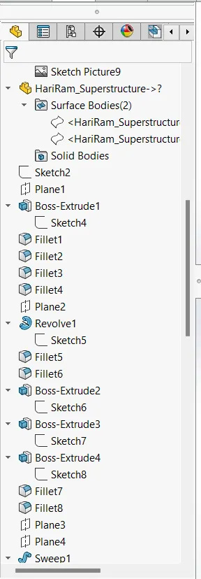
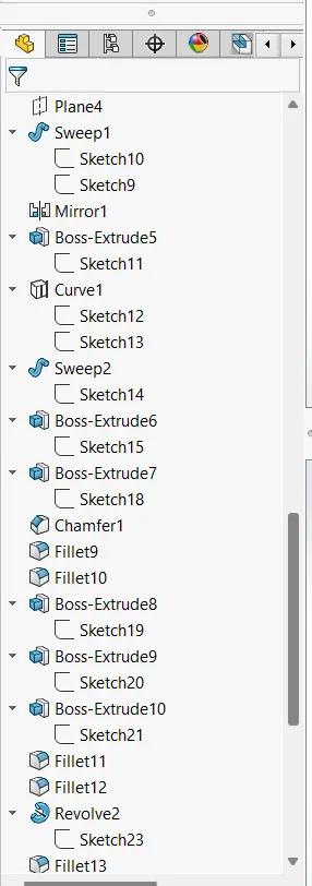
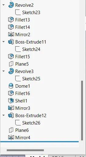
Feature Tree:
ASSEMBLY
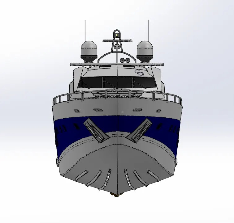
Front View:
Side View:
Isometric View:
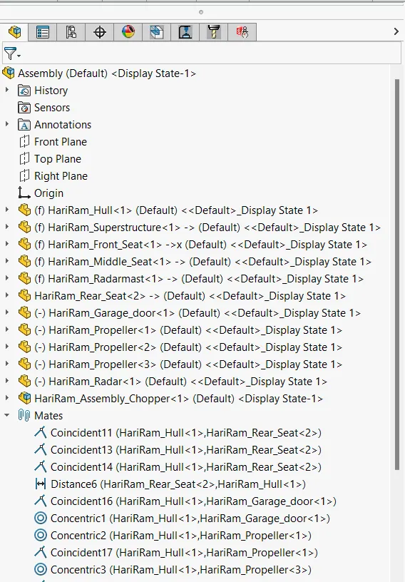
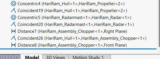
Feature Tree:
PROJECT REPORT ON SUNSEEKER YACHT
OBJECTIVE:
- To design the sunseeker yacht using solidworks software by creating each parts with the help of blueprints.
- To assemble all the parts belongs to sunseeker yacht to obtain complete model.
- To render the model using photoview 360.
INTRODUCTION
- SolidWorks is a solid modelling Computer Aided Design(CAD) and Computer Aided Engineering (CAE) application. This uses a parametric feature oriented approach inorder to design the models and assemblies.
- In the case of sunseeker yacht, most of the models are designed with the help of blueprints and uses surface modelling in majority design area.
- Photorealistic rendering place a major role in enhancing visualize effect to the model.
DESIGN METHODOLOGY:
- Initially blueprints are arranged to the planes so creating blueprint setup. It helps in assembly of the parts into a complete model.
- Propeller, Radar are made without the help of blueprint.
- Hull, front seat, middle seat, rear seat, radarmast,superstructure are modelled and appearances are given.
- Assembly is done by inserting each components at the right orientation by giving proper mating features between bodies.
- Render the model using photoview 360 and solidworks visualization.
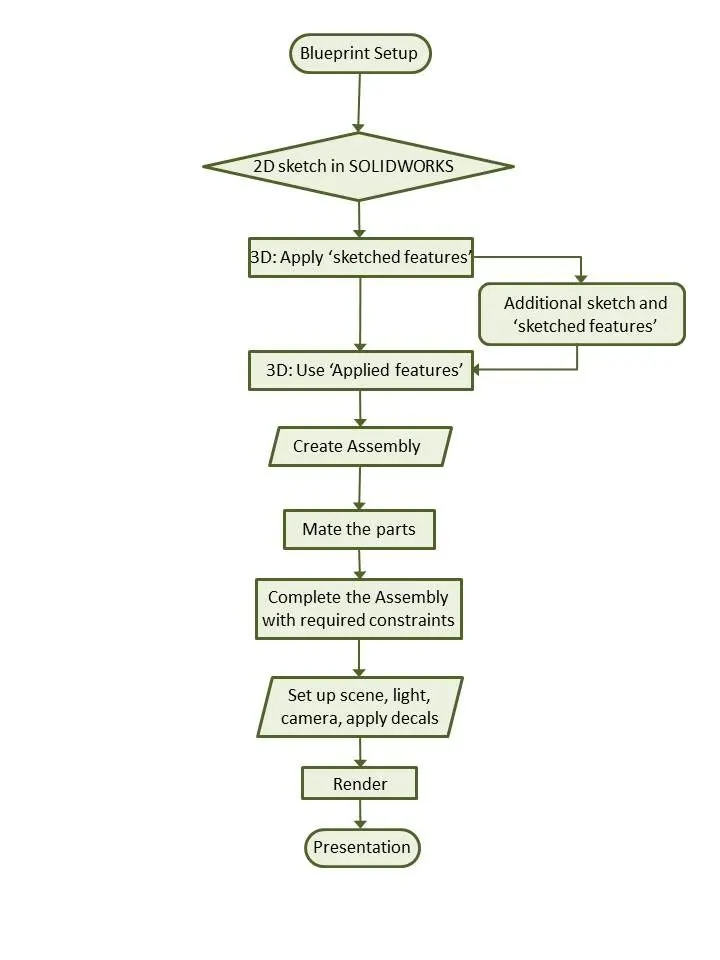
Surface Modelling: Surface Modeling is the method of showing or presenting solid objects. The process requires you to convert between different 3D modeling types, such as converting the 3D object to show procedural surfaces, validate imperfections, and apply smoothness.Surface modelling allows to create more free-form shapes. It is more definitive in nature. Creation of complex surfaces is easier in comparison with other modelling techniques.
TYPES OF COMMANDS USED:
- Sketch commands
- Surface commands
- Features
Sketch Commands
- Line : It is the most used tool while sketching. It can be Normal line, centreline and midpoint line.
- Circle : It is the tool which enables circular drawing in sketch. Solidworks has cirlces which can be drawn two ways. Normal circle and perimeter circle.
- Rectangle : It can be corner rectangle, centre rectangle, 3point corner rectangle, 3 point centre rectangle and parallelogram.
- Spline : It can be 2D and 3D curves which can be drawn with set of points. It can be changed into the model curves by adjusting the spline handles.
- Point
- Offset entities : It is used to copy the original sketch to a certain distance inwards or outwards.
- Sketch Fillet : Sketch fillet is used to trims away the corner at the intersection of two sketch entities to create a tangent arc.
- Straight Slot : It sketches a straight slot using the two end points.
- Text : This option is used to text the matter needed in the particular surface or plane.
- Sketch Picture : It is used to insert picturein sketch plane to obtain an underlay for 2 D sketches.
- Convert Entities : It will project edges of a face onto the active sketch whether or not the face is parallel to the active sketch.
- Smart Dimension : It is an essential tool to give the dimension for each sketch.
Feature Commands
- Extrude Boss/ Base : Extruded Boss feature adds material to the part model.
- Extrude Cut : It is used to remove material of a 3D model by 2D sketch.
- Swept Boss/Base : Split feature is used to sweep a closed profile along a closed or open path.
- Split Line : This command is generally useful when we need to create additional faces on a model without altering the geometry.
- Dome : It helps to create domes on 3D parts ar shapes by giving a curved surface around the selected surface.
- Projected Curve : It allows the user to create curves by projecting the selected curves onto the face of the user-defined solid or surface geometry.
- Piercing : The pierce point defines the location of the profile, relative to the sketch segment used to create the structural member.
- Reference Plane : The plane of reference (or reference plane) is the plane used to define orbital elements (positions).
- Fillet
- Chamfer
Surface Commands
- Extrude Surface : Sets the extrude Thickness equally in both directions from the sketch.
- Lofted Surface : The loft feature creates a shape by making transitions between multiple profiles and guide curves. This tool is very valuable for modeling complex surfaces.
- Swept Surface : Create planes for sketching the sweep profile, sweep path, and if necessary, the guide curves. Sketch the sweep profile and path on the planes that you created.
- Fill Surface : It is used to fill the material inside the profiles in the desired shape in which sketch is created.
- Trim Surface : Trim surface is the tool used to remove unwanted surface in model during modelling.
- Ruled Surface : The Ruled Surface command creates surfaces that extend out in a specified direction from selected edges.
- Knit Surface : It is used to combine two or more faces and surfaces into one.
- Extend Surface : It is used to extend any surface to certain extend.
- Offset Surface : Creating the surface as a copy of the original surface at a certain distance.
Part Modelling : Part modeling is the process of creating a virtual prototype of something by modeling each individual part separately, which can then all be assembled together to create the model of the final product.
DESCIPTION FOR PART MODELLING
1. PROPELLER
Propellers are used to pump the fluid inorder to create a thrust which initiates the ship to move through water.The rotational motion of the baldes which are present in propellers create a difference in pressure by Bernoulli's principle between the surfaces of the blade.
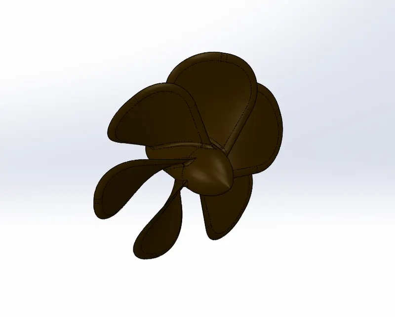
Sketch Commands used:
- Line
- Circle
- Spline
Features used:
- Revolved Boss/ Base
- Lofted Boss/ Base
- Fillet
- Extrude Cut
- Circular Pattern
2. RADAR
Radars are used to detect the obstacles and ships in the way of navigation in sea to avoid collision with foreign objects.
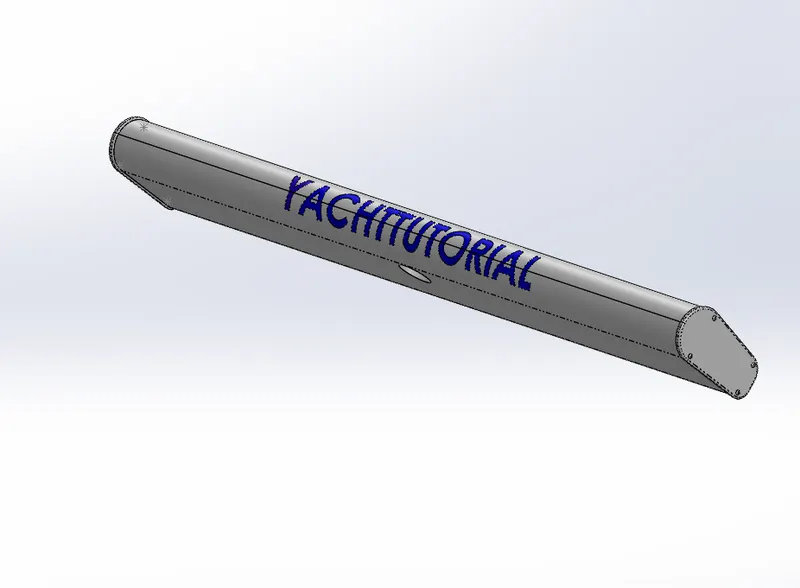
Sketch Command used:
- Line
- Circle
- Point
- Text
Features used:
- Extrude Boss/ Base
- Extrude Cut
- Fillet
- Split line
- Mirror
3. HULL
The hull of a ship is the most notable structural entity of the ship. To define the hull, it can be said that it is the watertight enclosure of the ship, which protects the cargo, machinery, and accommodation spaces of the ship from the weather, flooding, and structural damage.The forward most contour of the ship’s hull is called the bow, and the aft-most, its stern. The stem is the forward most contour part of the bow.
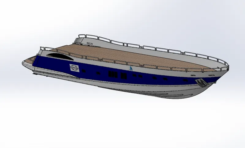
Sketch Commands used:
- Line
- Circle
- Straight slot
- Sketch picture
- Arc
- 3D Sketch
- 3point corner rectangle
- Spline
Features used:
- Extrude Boss/ Base
- Extrude Cut
- Extrude Surface
- Surface Trim
- Surface Fill
- Lofted Surface
- Swept surface
- Swept Boss/ Base
- Delete Face
- Knit Surface
- Fillet
- Chamfer
- Mirror
- Split Line
- Projected Curve
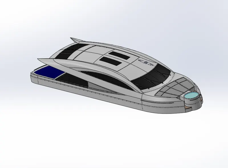
4. Superstructure
The superstructure of a ship is the part of it that is above its main deck.The size of the superstructure has a great influence on the mobility of the vessels. They are designed in a manner, so that, they add value and hinder the speed and mobility in the least. The superstructure is mostly designed in fashion as well. This is because it is the most easily visible part of the ship, in fact it is the identification of the ship, and so the designers try to provide it with the identity that is unique.
Sketch Commands Used:
- Line
- Spline
- 3 D Sketch
- Centerline
- Circle
- Rectangle
- 3 Point Corner Rectangle
- Centrepoint Arc
Sketch Tools Used:
- Pierce Relation
- Convert Entities
- Trim
- Offset Entities
- Split Entities
Features Used:
- Surface Extrude
- Reference Plane
- Surface Sweep
- Surface Knit
- Fillet
- Ruled Surface
- Surface Trim
- Projected Curve
- Surface Loft
- Surface Fill
- Extend Surface
- Delete Face
- Extrude Boss/ Base
- Extrude Cut
- Rectangle
- Surface Offset
- Thicken Boss/ Base
- Dome
- Solid Sweep
- Split Line
- Mirror
- Chamfer
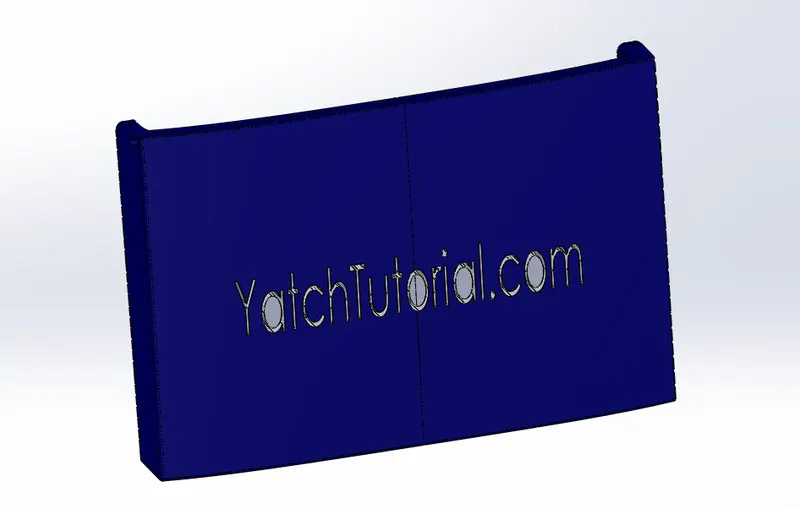
5. Garage Door
It is the part that uses to close the Garage portion in the hull. It can be used either manually or automatically. The garage is used to store or accomodate large or other automobiles and other equipments etc.
Sketch Commands Used:
- Line
- Circle
- Centreline
- Text
Features Used:
- Extrude Cut
- Shell
- Fillet
- Reference Plane
- Mirror
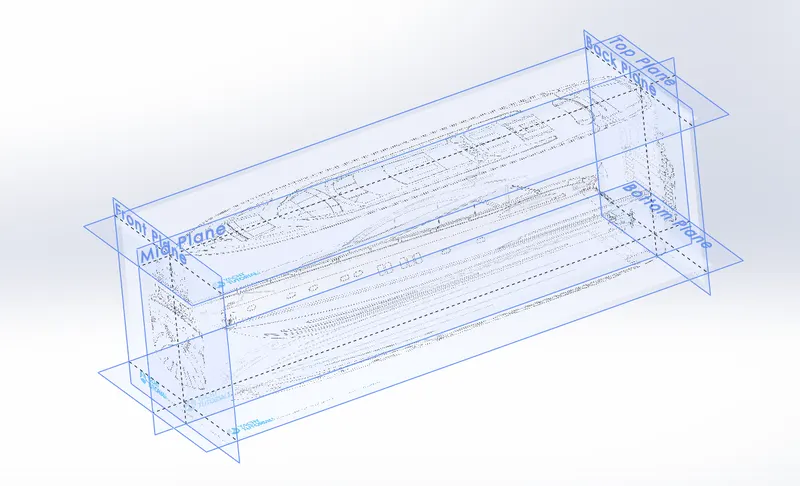
6. Blueprint Setup
It is the setup in which the views in different directions are arranged in each plane and it helps to draw the design model with a clarity. It helps the designer in the designing area.
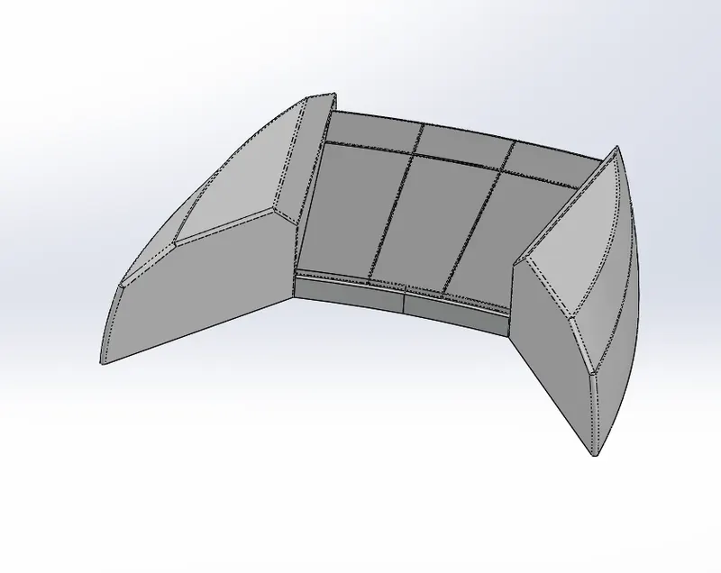
7.Front Seat
Sketch Command Used:
- Spline
- Line
- Centerlines
- Corner Rectangle
Sketch Tools Used:
- Convert Entities
- Trim
- Offset Entities
Features Used:
- Reference Plane
- Surface Sweep
- Surface Extrude
- Surface Trim
- Surface Fill
- Surface Loft
- Surface Knit
- Chamfer
- Revolve Boss/ Base
- Extrude Cut
- Fillet
- Mirror
- Dome
8. Middle Seat
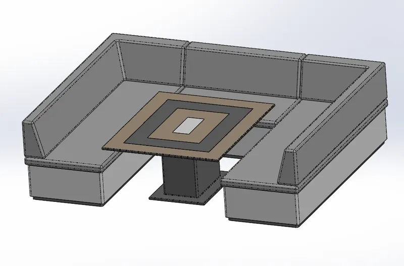
Sketch Commands Used:
- Lines
- Corner Rectangle
Sketch Tools Used:
- Offset Entities
- Trim
Features Used:
- Extrude Boss/ Base
- Reference Plane
- Chamfer
- Fillet
- Mirror
- Extrude Cut
9. Rear Seat
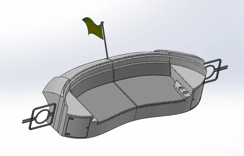
Sketch Commands Used:
- Lines
- Spline
- Circle
- Corner Rectangle
- Centerline
Sketch Tools Used:
- Convert Entities
- Offset Entities
- Trim
Features Used:
- Reference Plane
- Surface Sweep
- Surface Offset
- Surface Trim
- Ruled Surface
- Surface Knit
- Extend Surface
- Surface Extrude
- Surface Loft
- Extrude Boss/ Base
- Extrude Cut
- Chamfer
- Fillet
- Solid Sweep
- Mirror
- Revolve Boss/ Base
10. Radarmast
Radarmast is the portion in which radar is mounted inorder to navigate another foreign objects in sea. It consists of antennas, radar, rails to support etc.
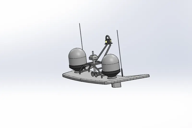
Sketch Commands Used:
- Line
- Spline
- Centerline
- 3 Point Arc
- Circle
- Rectangle
- Straight Slot
Features Used:
- Reference Plane
- Extrude Boss/ Base
- Fillet
- Revolve Boss/ Base
- Solid Sweep
- Mirror
- Chamfer
- Projected Curve
- Revolve Boss/ Base
- Dome
- Shell
Assembly
Assembly is the design area in which the individual parts which are already designed by the designer is attached together to get the actual model. It is done by inserting parts one by one in the assembly area of solidworks. The assembly operation is done by using different types of mates.
Command Used in Assembly:
- Insert components
- Mate
Mates Used in the Assembly:
- Coincident Mates
- Distance Mates
- Concentric Mates
Assembly Procedures:
- Initially the hull is inserted to the space.
- One by one we are inserting superstructure, radarmast, front seat, middle seat . It will be inserted at the correct location due to drawn methods.
- While inserting rear seat, we are giving coincident mates and distance mates.
- For propeller to perfectly work, we are giving concentric mate and coincident mate.
- For the radar also, we are giving concentric mate.
Views of Assembly:
Front View
Side View
Isometric View
Photorealistic Rendering using Photoview 360 and Solidworks Visualizer
Rendering:In 3-D graphic design, rendering is the process of add shading, color and lamination to a 2-D or 3-D wireframe in order to create life-like images on a screen. Rendering may be done ahead of time (pre-rendering) or it can be done in on-the-fly in real time.
Appearances: Various types of appearances can be given to each model which is enhancing the visualizing effect of the model.
Light, Camera settings in photoview 360
In solidworks we can give perfect decals light and camera views to our model. It can be rendered as a view using photoview 360.
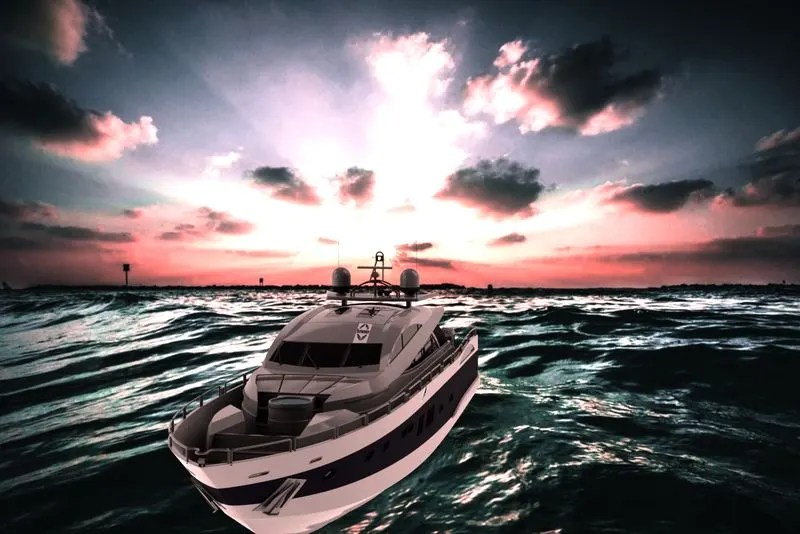
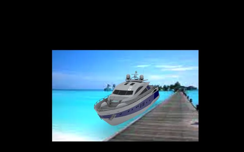
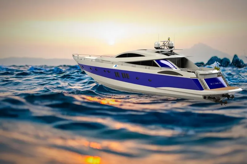
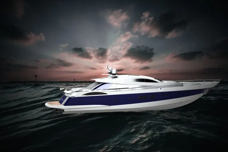
Rendered Images for Sunseeker Yacht
In the rendered images, I had tried to give different visualizing aspects such as bloom, exposure, gamma connection, lightens etc.
Conclusions:
By completing the sunseeker yacht model, we are able to know about
- Designing the individual models using different tools and features.
- Giving appearances to the models to enhance.
- Rendering the models using different light camera settings and scene settings.