Radar Mast & Final Assembly of Yacht
MODELLING AND ASSEMBLY OF SUNSEEKER PREDATOR YACHT
OBJECTIVE:
To design the different parts of the yacht as per given dimensions, assemble entire model and render it using photoview 360 and solidworks visualize.
INTRODUCTION:
Here we use SolidWorks software to bring out our design ideas to life virtually. In the modeling of the sunseeker predator yacht, we design by help part module by using 2D, and 3D sketches and converting them into 3D models. We modeled most of our parts using blueprints. Here we used surface modeling and then converted them into solid bodies because more layers of surfaces are included in this design. Assembly plays an important role in bringing the 3D models to real life.
The components which designing, modeling and assembly of sunseeker predator yacht are:-
- Propeller.
- Radar.
- Hull.
- Garage Door.
- Front Seat.
- Middle Seat.
- Rear Seat.
- Superstructure.
- Radar Mast.
DESIGN APPROACH:
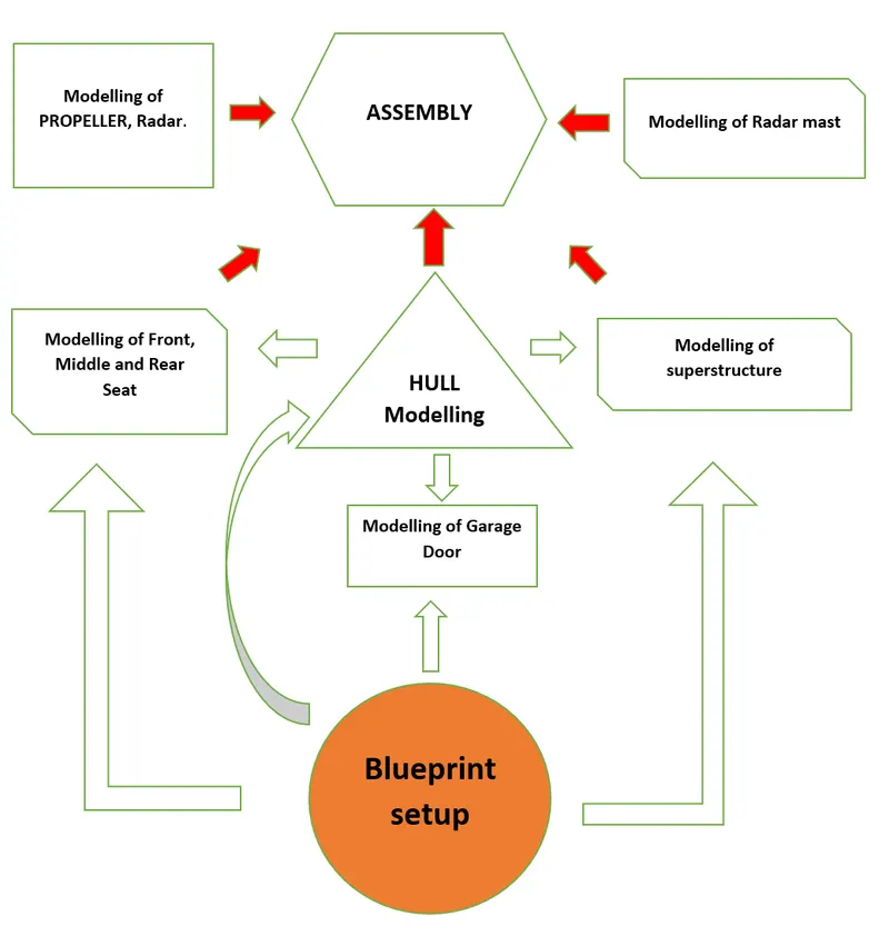
COMMANDS USED AND THEIR EXPLANATION:
SKETCH COMMANDS:
Designing any model usually starts with a sketch.
Line: we can draw horizontal, vertical, and angular lines.
Circle: it is used to create a circular drawing and there are two types of circles we can draw one is the center circle and the other is a perimeter circle.
Rectangle/ slots: we can create rectangles, square and the different types of rectangle like corner rectangle, 3 point rectangle, and 3 point center rectangle.
Spline: it is a type of curve that has a control point to control the angle and curvature of the curve.
Text: we can write the text on surface or solid bodies or on planes and then project it on surfaces/ solid bodies. We can also Allain them, change font, size, etc.
Offset entities: we use this command to copy the existing sketch in two directions by specifying a certain distance (offset distance).
Convert entities: this command can copy the previous sketches or surfaces in the current sketch and it is fully defined. It is just like offset entities with zero offset distance.
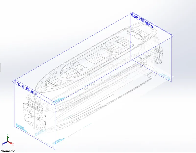
Sketch picture: we insert image as the background of sketches to reverse engineer the model and we can specify the location and angle in sketch properties which helps us to create an accurate sketch.
FEATURE COMMANDS:
Extrude Boss: This feature will be performed after the 2D sketch is a closed figure and fully defined it is converted the 2D sketch into a solid body. When we exit the fully defined sketch we get boss extrude option in the feature tab. It creates a complete solid body of closed entities of any size and shape. In this feature, we can add dimensions to both direction (direction 1 and direction 2) as per requirement. We can also use the default direction options it is blind, through all, up to next, etc. the extrude can start from the surface, midplane, from the vertex, off-set surface, etc. here we mostly used off-set from surface to extrude.
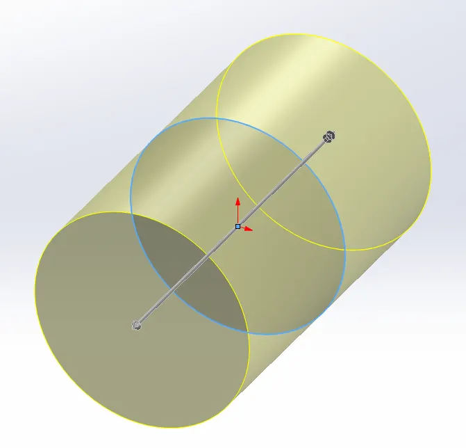
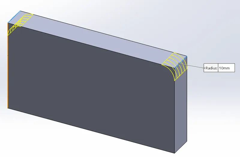
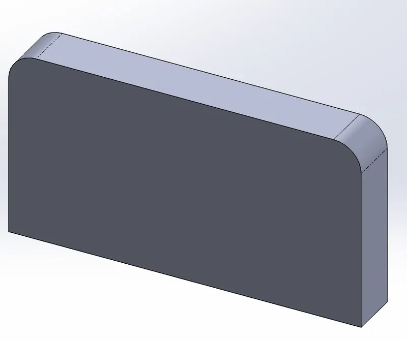
Fillet: This feature is used to make sharp edges machinable. To make those edges curve we add fillets. We can perform it in different sizes or radius. Various types of fillets end fillet, edge/total fillet.
Revolve boss feature: This feature works on-axis, by revolving the sketch around that axis. If there is no axis/reference line we can select an edge to be the reference for a sketch and it gives us appropriate geometry.
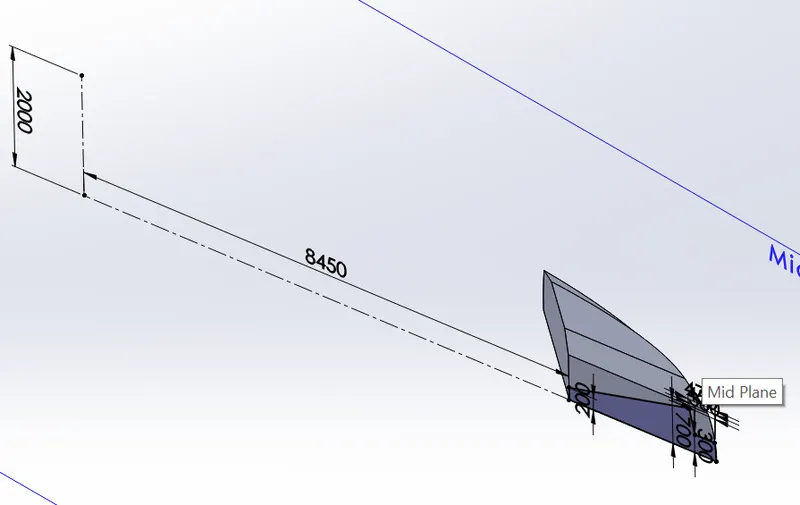
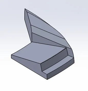
Extrude cut: As the name says when we want to remove material from the solid part we draw the sketch on the solid part and then we use extrude cut command it removes that part/surface from the original body.
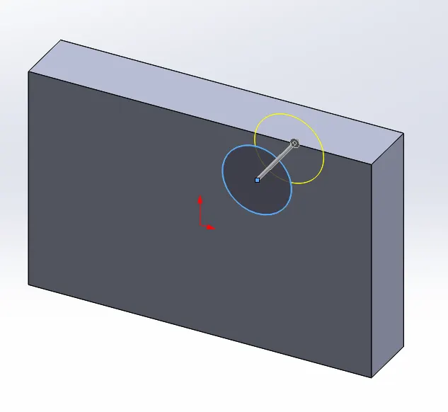
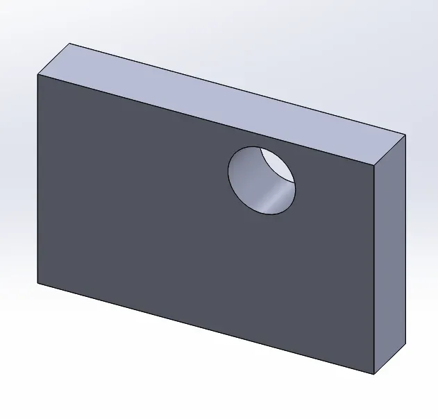
Sweep: it will create a solid sweep of the closed profile over the path that has been selected.
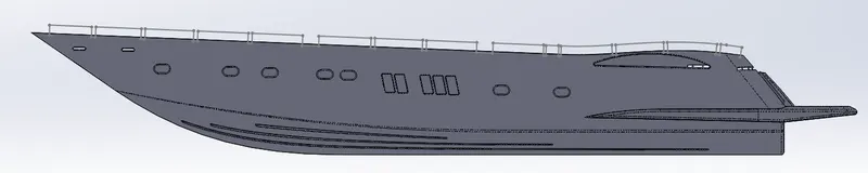

Dome: we can create a circular dome on any surface by giving an input radius.
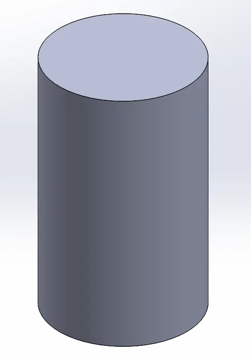
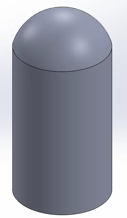
Shell: It can convert solid objects to the hollow in this tool we give inside thickness to the geometry and material will be removed from the body and it becomes hollow.
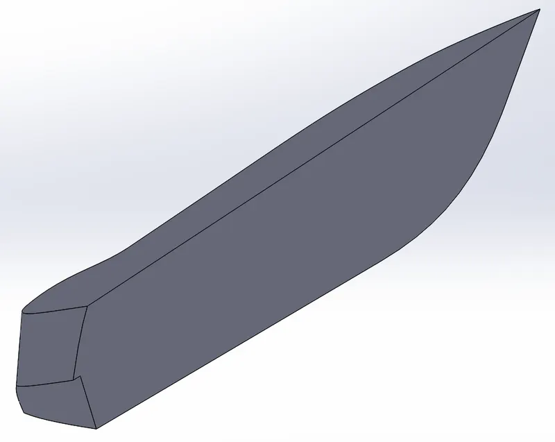
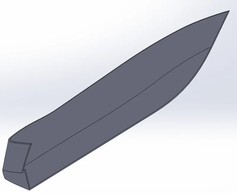
Linear pattern: The linear pattern is used to create a single sketch/extrudes/extrude cut to use multiple times. In given angles/paths. This sketch/ extrudes are spaced uniformly.
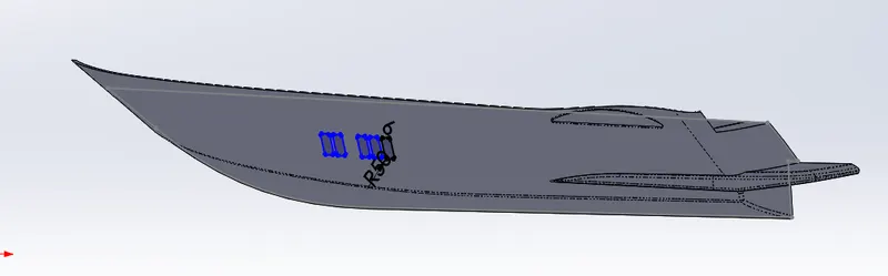
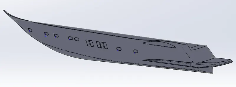
Circular pattern: Circular pattern is used to create a single sketch/extrudes/extrude cut to use multiple times. In a given circular path. This sketch/ extrudes are spaced uniformly.
Mirror: This feature creates copies of sketches and solid parts. When this feature is applied it needs a plane or axis as a reference to be mirrored. Select the body/sketch which is to be a mirror, select an axis or plane then apply the feature and the mirrored part will be automatically generated.
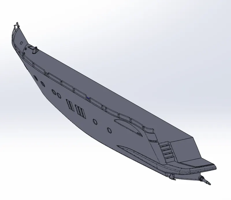
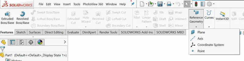
Reference geometry: If we want to create any new references in the sketch-like axis, point, and plane at any required angle we use reference geometry.
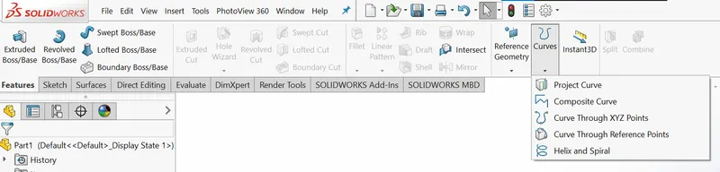
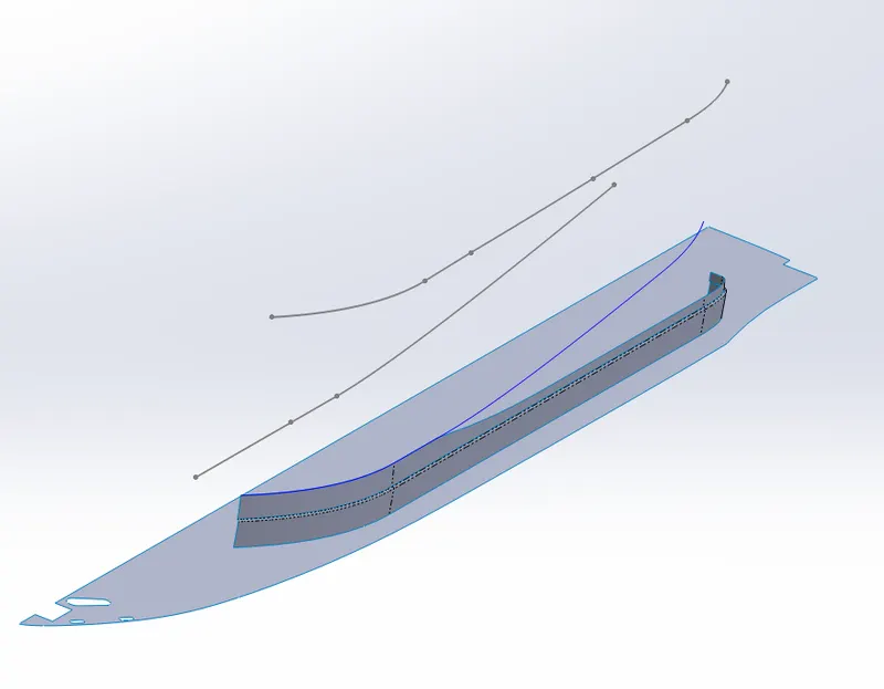
Projected curve: The curve we create in two different 2D planes is projected in a 3Dspace. Generally, the curves are to be extruding surfaces. The curve extrusions will intersect and form a new curve in the space called intersecting curves. The BLUE colour line shows the projection curve.
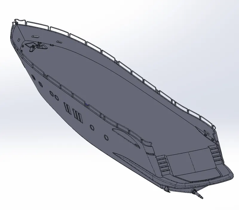
Split Lines: with this command, we can divide a solid/surface into two different surfaces which helps us in applying different appearances.
SURFACE COMMANDS:
Extrude Surface: convert the 1D sketch to 2D surface.
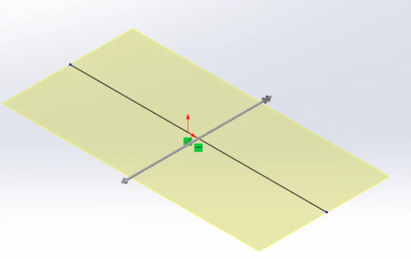
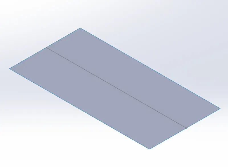
Ruled Surface: here the 2D surface is created from the edge of other surfaces to a specified direction and distance in tangential, normal, and in some specified angles.
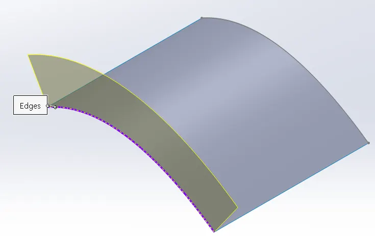
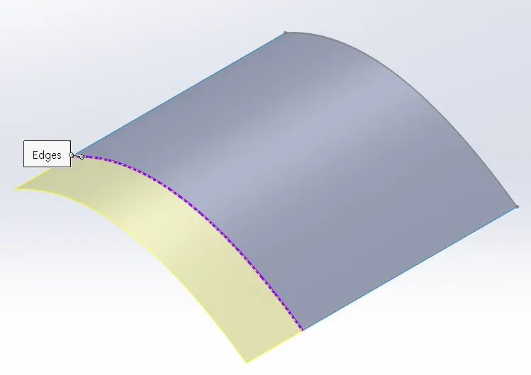
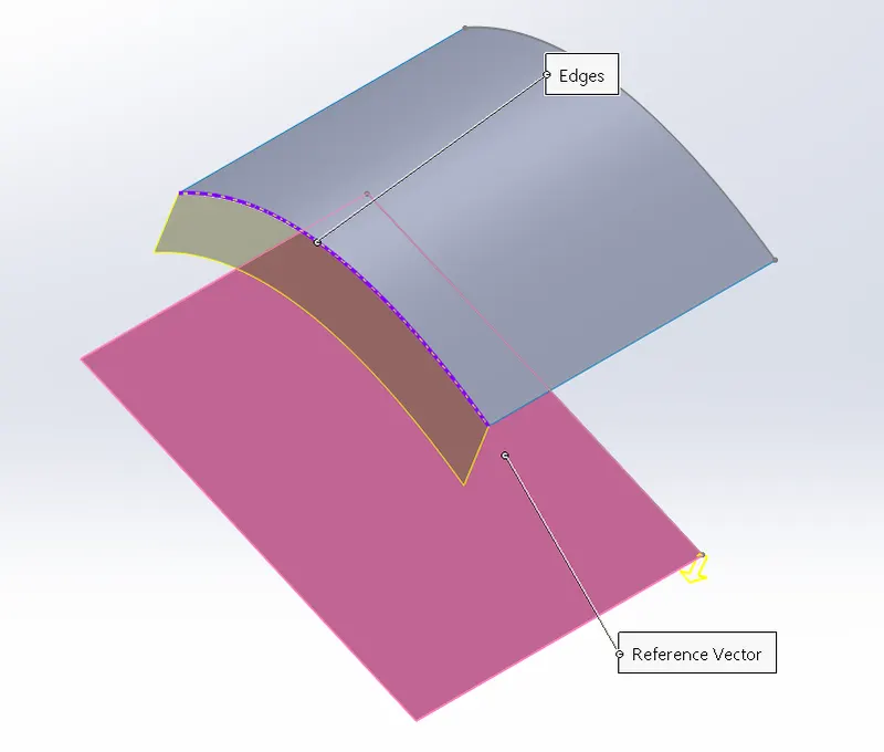
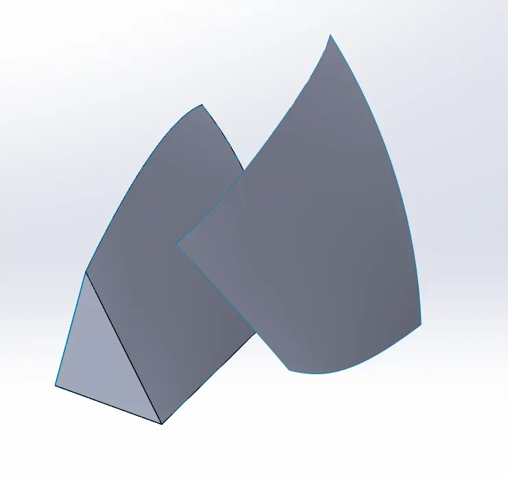
Surface Trim: This feature is used to remove the extra surface/ whatever surface we like to remove/keep. It is just like the ‘TRIM’ command in the 2D sketch.
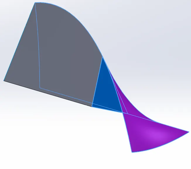
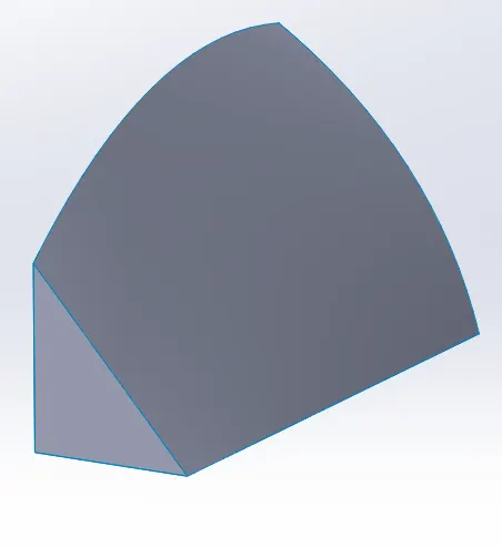
Surface Extend: This command is used to extend the existing surface to a particular distance.
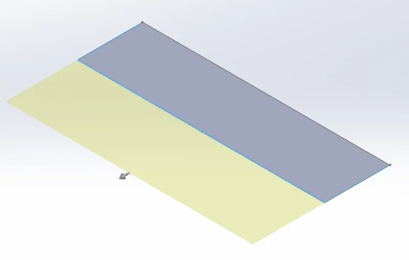
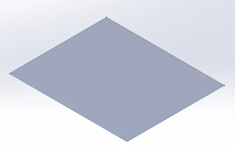
Surface Fill: By selecting all the boundaries we can fill it with a surface by using this command.
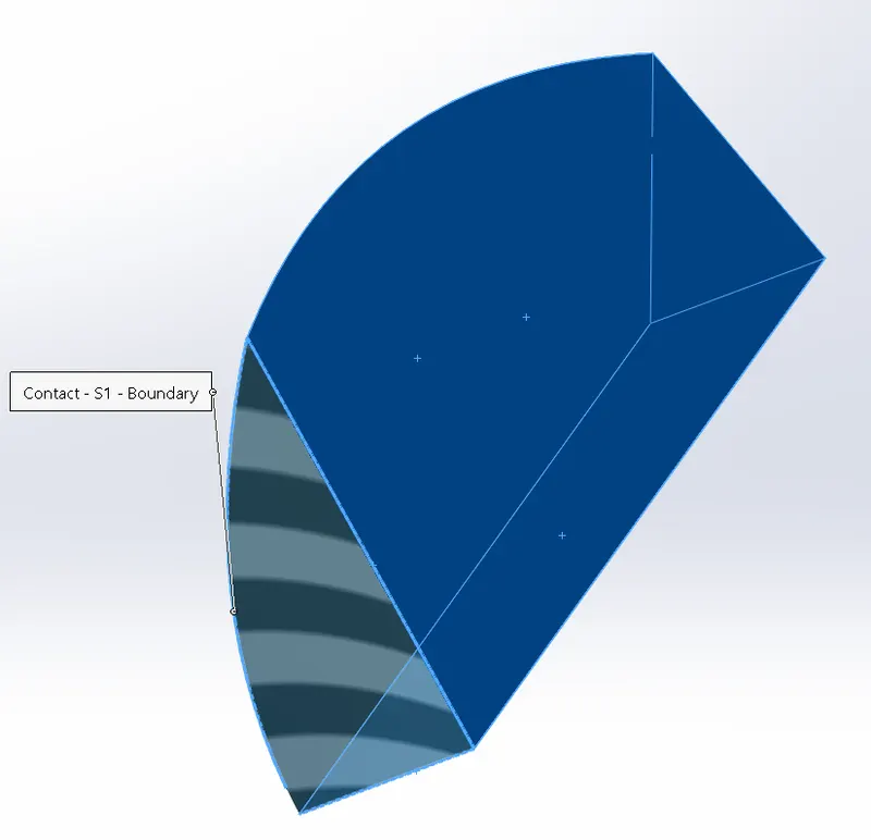
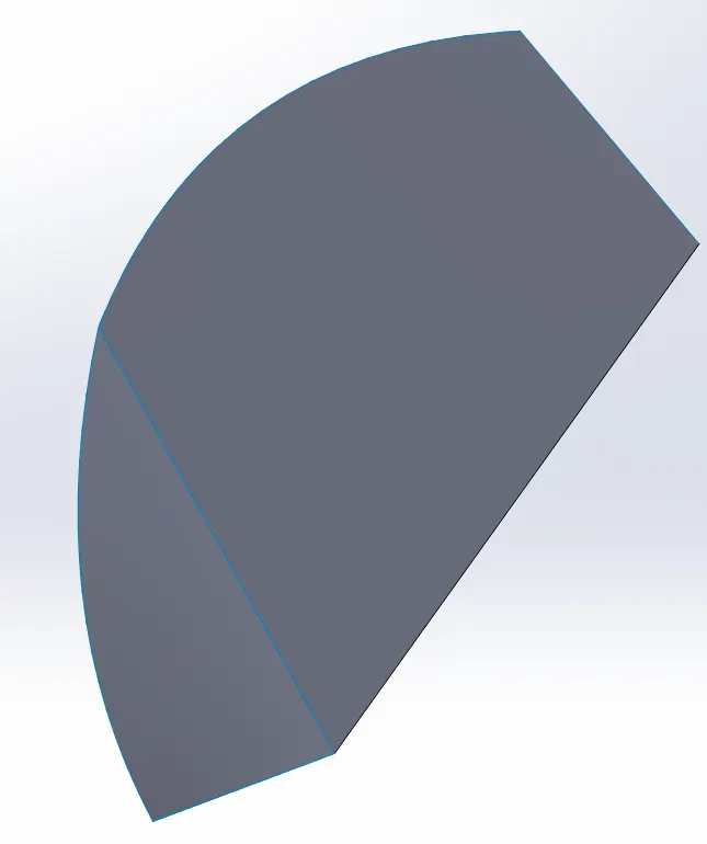
Surface loft: This feature is used to convert 2D drawings to 3D surfaces. Here we can specify the direction of the surface to be loft by guidelines.
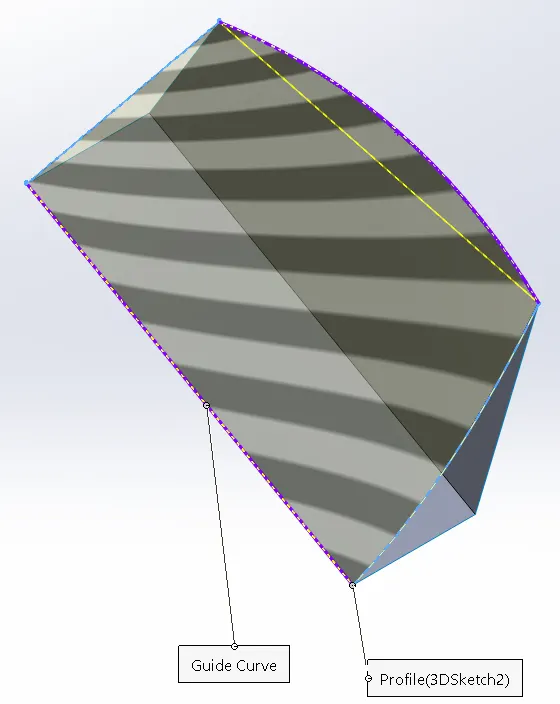
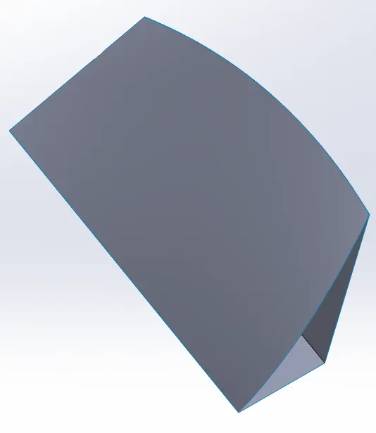
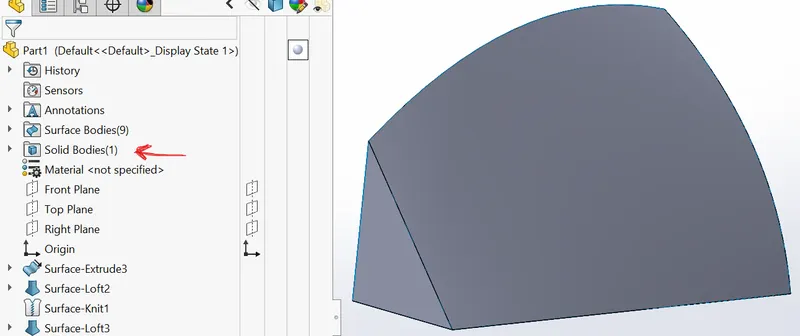
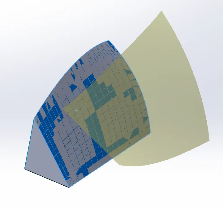
Surface Knit: Use of knit surface tool to combine two or more surfaces into one. If the surface is perfectly joint, we can use an option called CREATE SOLID from here.
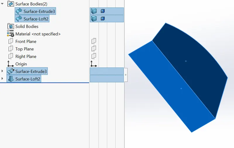
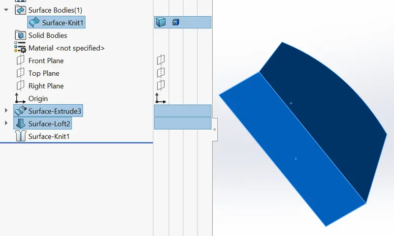
Create Solid:
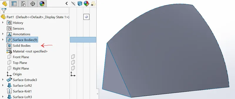
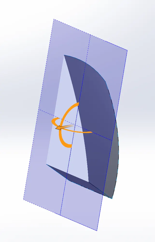
Delete Face: As the name suggests we delete any surface and also fill it with a new surface to remove small gaps.
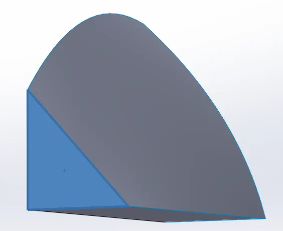
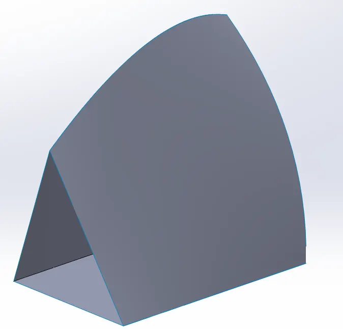
Off-set Surface: works same as off-set entities command in sketch but it is applicable only for surfaces. The surfaces are off-steed with the same properties.
ASSEMBLY COMMANDS:
Mate: it is a command used in assembly to join the two parts in any of these following relations.
The relations are:-
- Coincident mate: Coincident mate makes two planar faces to become coplanar. This mate is used when two surfaces are inseparable.
- Concentric mate: This makes two circular faces/bodies become concentric and can move along the same axis.
- Tangent mate: This feature can be used between two faces/planes to make tangent relation between them.
- Distance mate: this feature is used to fix or coincide a body at a certain distance.
- Parallel mate: this feature is used when we want to make some edges, faces, and planes parallel.
PART MODELLING:
1. BLUEPRINT SETUP:
We use images of the yacht to reengineer it into the model.
2. PROPELLER:
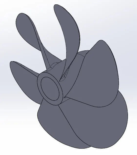
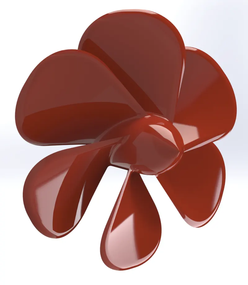
There are three propellers in this yacht it is a part that is used to create the thrust required to move the yacht in forward direction by revolving underwater. It is the fully submerged body of the yacht.
Commands used to model:
Sketch:
- Spline
- Circle
- Line
Feature:
- Revolve boss/base
- Lofted boss/base.
- Extrude cut
- Reference plane
- Circular pattern
- Fillet
Rendered image:
3. RADAR:
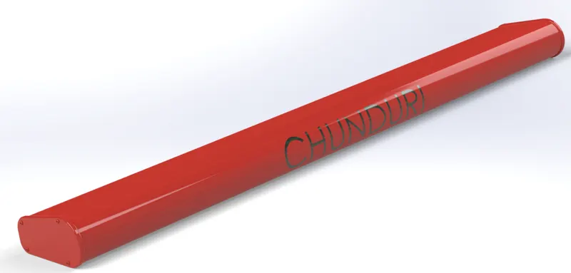
It is used to detect other ships and obstacles to prevent collision and navigate at the sea.
Commands used to model:
Sketch:
- Text
- Circle
- Line
Feature:
- Extrude boss/base
- Extrude cut
- Mirror
- Fillet
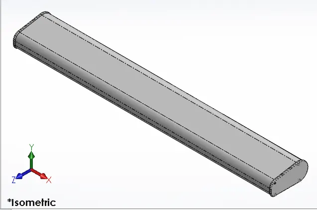
Rendered image:
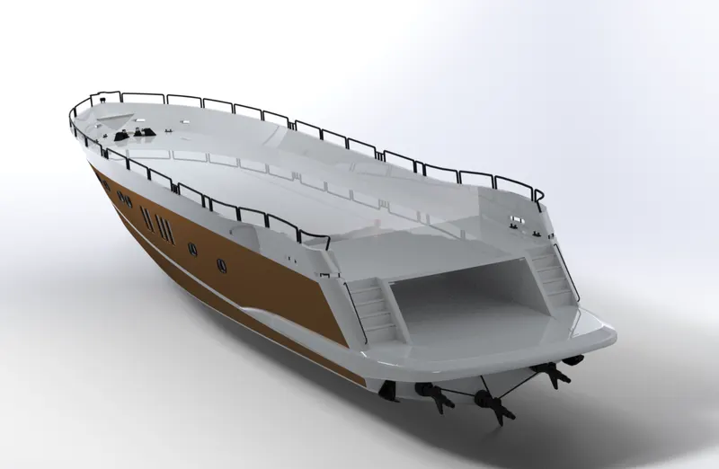
4. HULL:
It is the most important part structure of the yacht where all the load acting on the yacht is transferred. It is the watertight body of the ship/ yacht. It is the only partially submerged body of the yacht. It is the strongest part and it flows over the water.
Commands used to model:
Sketch:
- Spline
- Circle
- Line
- Rectangle
- Slot
- Arc
- 3D Sketch
- Convert entities
- Off-set entities
- Sketch picture
Surface:
- Extrude surface
- Revolve surface
- Lofted surface
- Surface trim
- Surface fill
- Knit
- Delete face
Feature:
- Projection curve
- Split line
- Extrude boss/base.
- Extrude cut
- Circular pattern
- Fillet
- Chamfer
- Mirror
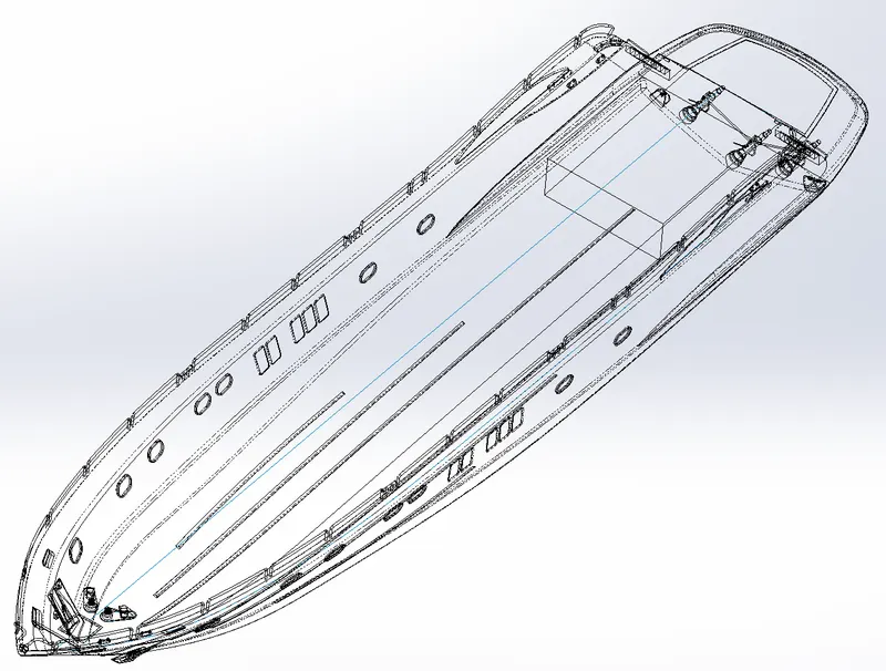
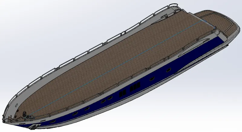
Rendered image:
5. GARAGE DOOR:
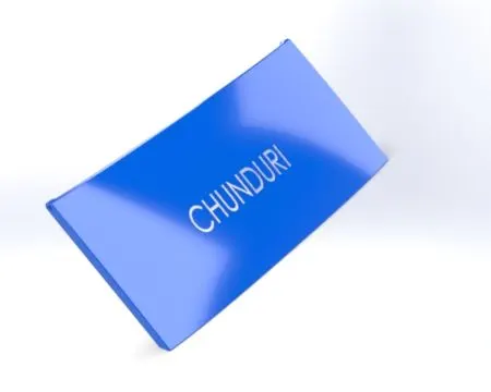
With the help of save body options, we had created apart from the hull or can perform the same operation with the help of split command. This option is used to maintain the same curvature of the original body and the body goes in the same place at the time of assembly. It is the door that opens electrically.
Commands used to model:
Sketch:
- Spline
- Circle
- Line
- Text
Feature:
- Extrude cut
- Reference plane
- Shell
- Fillet
- Mirror
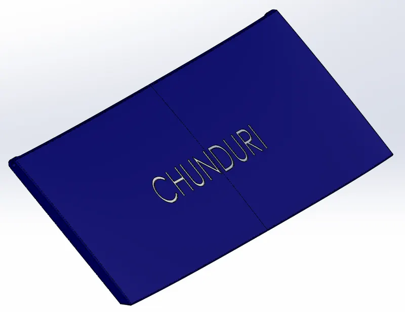
Rendered image:
6. FRONT SEAT:
Commands used to model:
Sketch:
- Sketch picture
- Spline
- Circle
- Line
- Arc
Surface:
- Extrude surface
- Revolve surface
- Swept surface
- Lofted surface
- Surface trim
- Surface fill
- Knit
- Delete face
Feature:
- Revolve boss/base
- Extrude cut
- Dome
- Chamfer
- Fillet
- Mirror
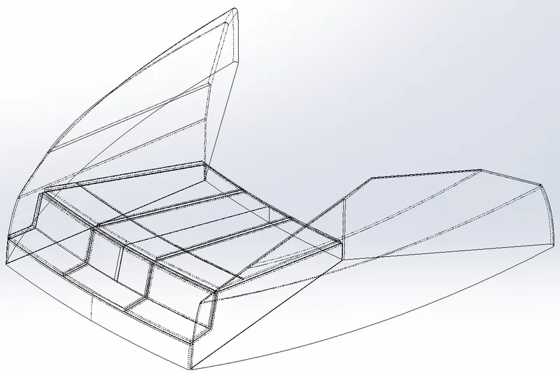
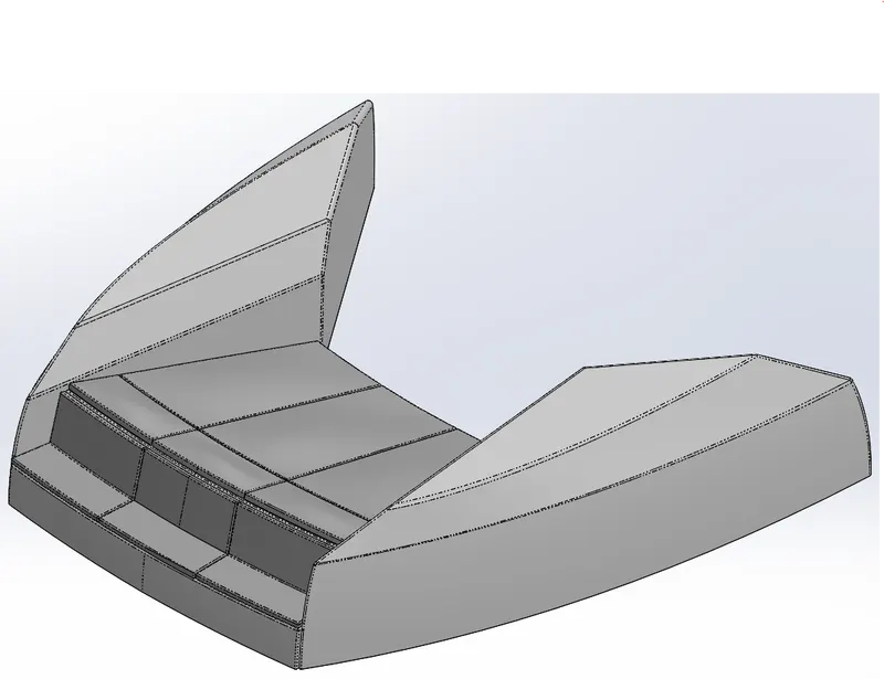
Rendered image:
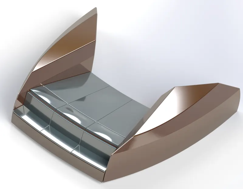
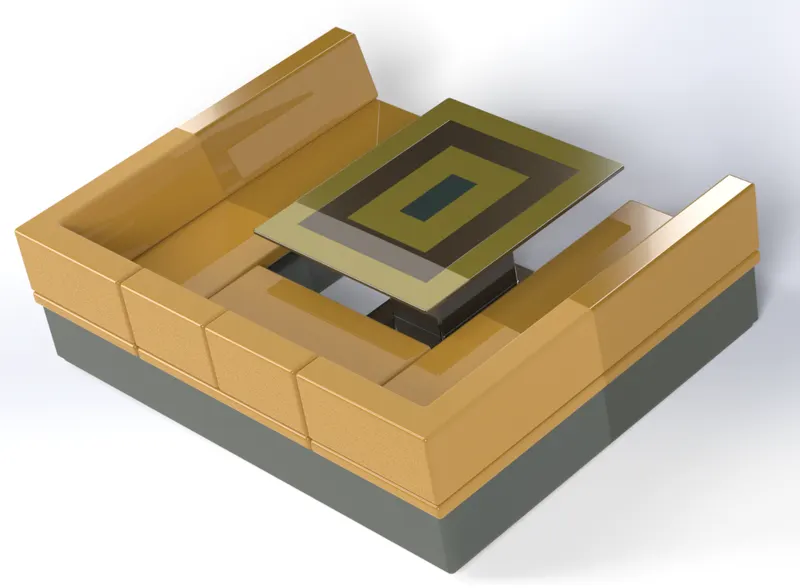
7. MIDDLE SEAT:
Commands used to model:
Sketch:
- Sketch picture
- Line
- Rectangle
Feature:
- Extrude cut
- Reference plane
- Chamfer
- Fillet
- Mirror
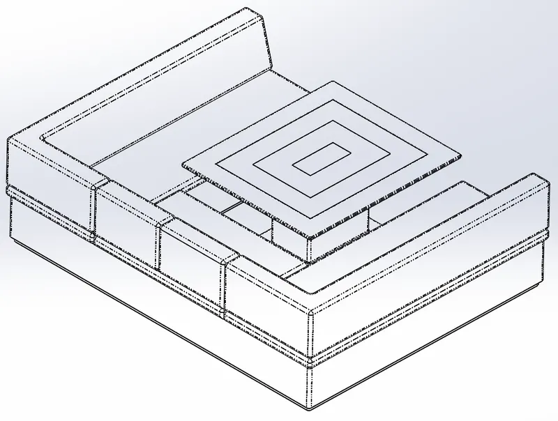
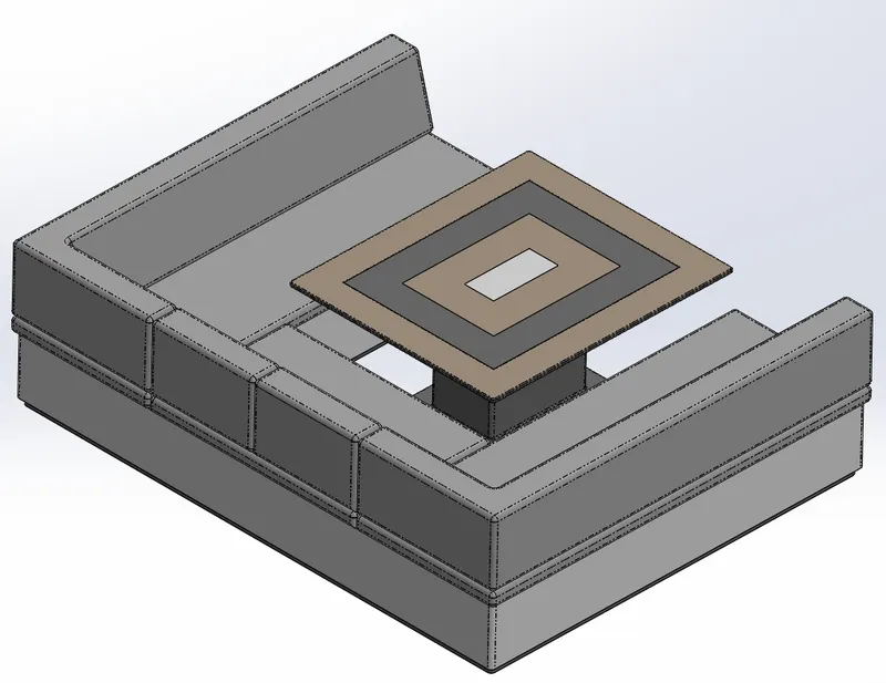
Rendered image:
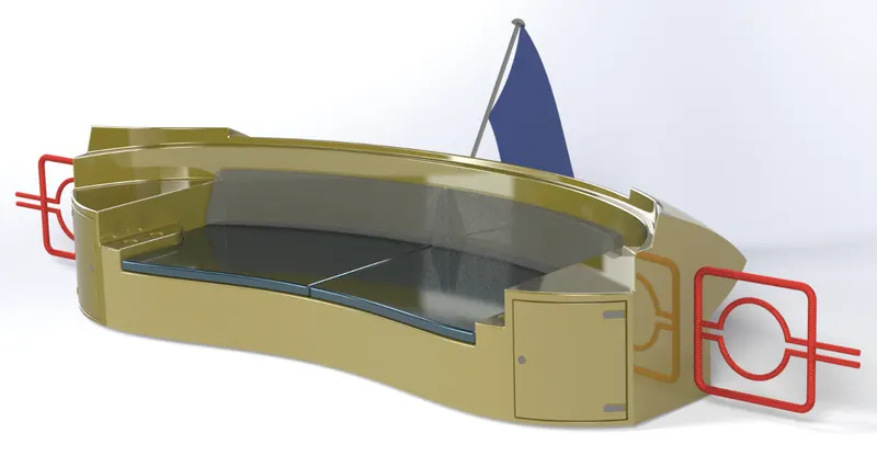
8. REAR SEAT:
Commands used to model:
Sketch:
- Sketch picture
- Spline
- Circle
- Line
- Arcs
- Rectangle
Surface:
- Extrude surface
- Off-set surface
- Swept surface
- Lofted surface
- Surface trim
- Ruled surface
- Knit
Feature:
- Reference plane
- Revolve boss/base
- Extrude boss/base
- Fillet
- Mirror
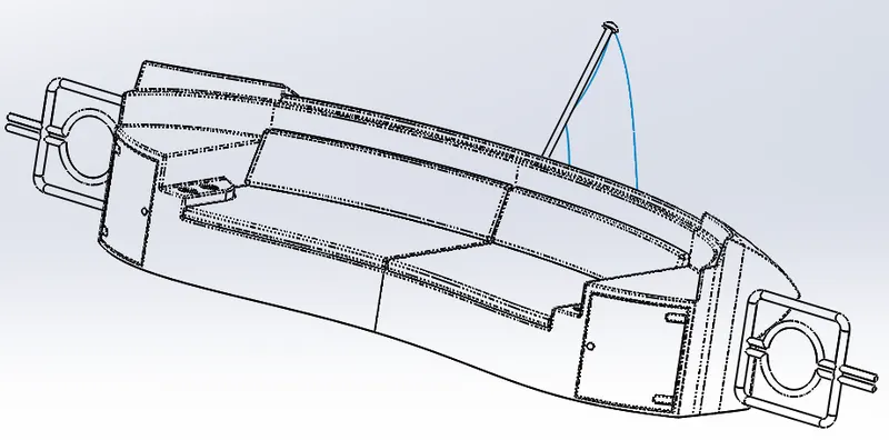
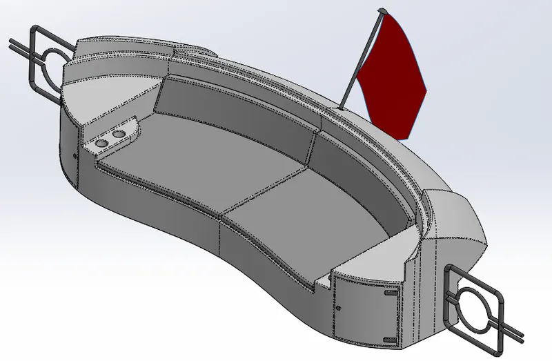
Rendered image:
9. SUPERSTRUCTURE:
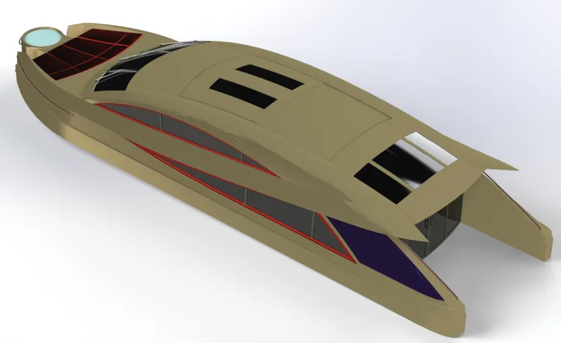
It is mounted on the hull known as the deck surface. This is the part of the yacht that mostly uses surface modeling techniques.
Commands used to model:
Sketch:
- Sketch picture
- 3D sketch
- Spline
- Circle
- Line
- Center point arc
- Rectangle
- Convert entities
- Off-set entities
Surface:
- Extrude surface
- Ruled surface
- Swept surface
- Lofted surface
- Surface trim
- Extend surface
- Knit
Feature:
- Reference plane
- Projection curve
- Split line
- Extrude boss/base
- Extrude cut
- Fillet
- Chamfer
- Mirror
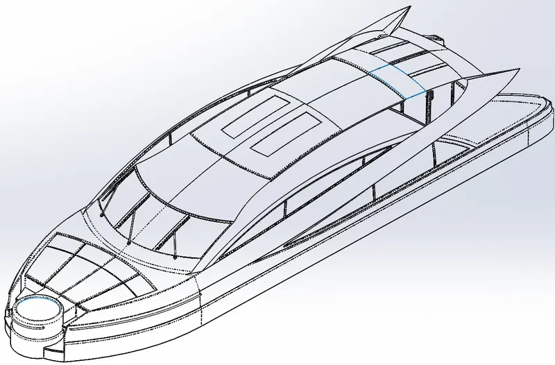
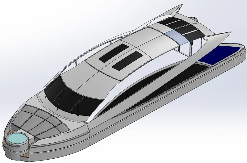
Rendered image:
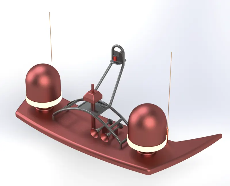
10. RADAR MAST:
It is mounted on the superstructure. It holds radar, navigation system, lights, and horns flags on it.
Commands used to model:
Sketch:
Sketch picture
- Line
- Spline
- Rectangle
- Arc
Feature:
- Extrude boss/base
- Extrude cut
- Sweep boss/base
- Revolve boss/base
- Reference plane
- Projection curve
- Chamfer
- Fillet
- Mirror
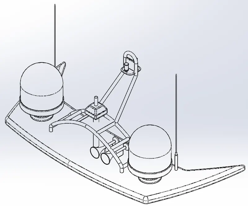
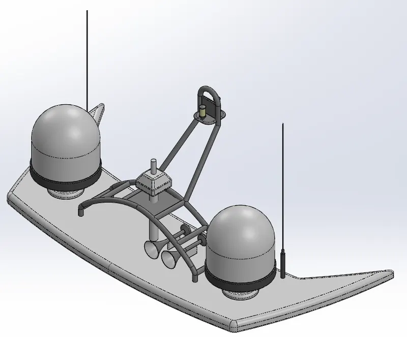
Rendered image:
ASSEMBLY:
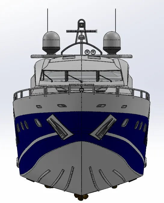
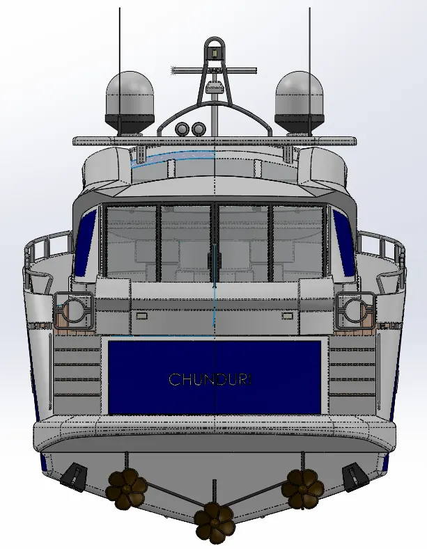
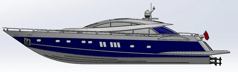
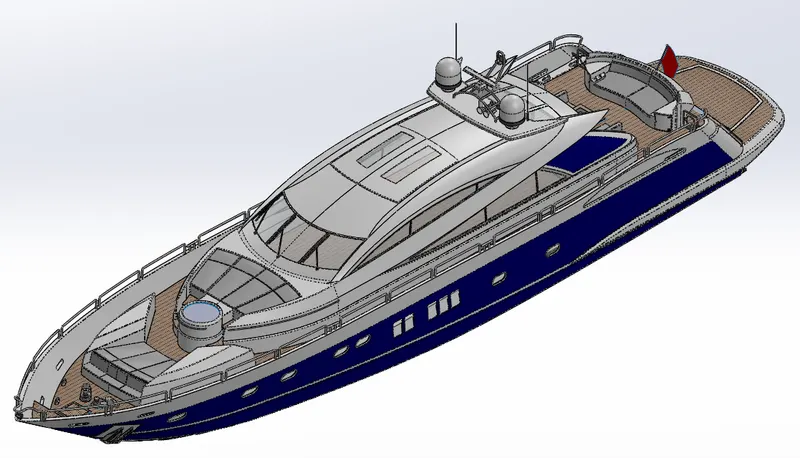
An assembly is a module in solid works where all the parts of the desired machine are assembled. Here we have to import all the components of yacht and use mate options or just import and click ok(because we have designed some parts with the reference to the other parts).
Example: we have designed the superstructure in reference to the hull deck surface.
Front view: Back view:
Side view:
Isometric view:
RENDERING:
In Computer-Aided Design (CAD) a rendering is a particular view of our assembly/body as realistic as possible.
By using PHOTOVIEW 360:
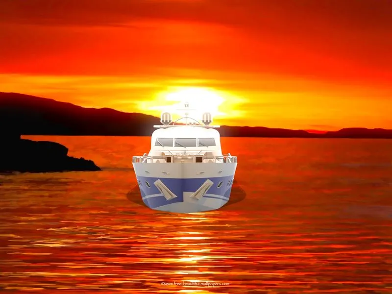
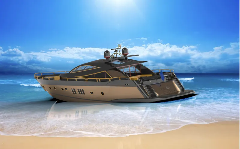
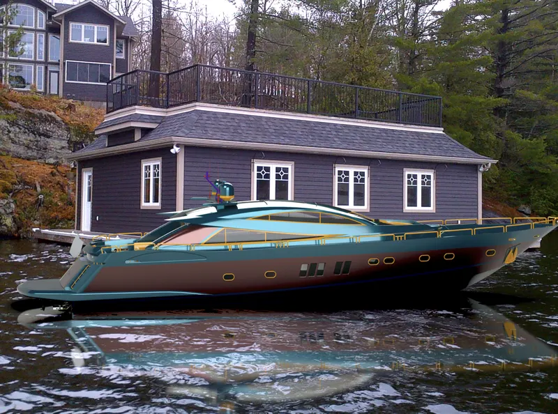
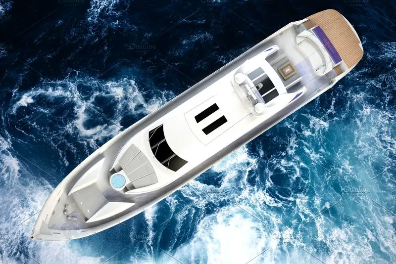
We can use the camera, lighting, bloom, cartoon/counter, different background, environment,s and also schedule renders with the help of the task scheduler tool. We can change color, brightness and gamma values after rendering also, and also can compare the previous render image with the current render image.
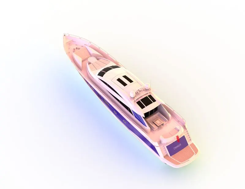
This rendering is done in the SOLIDWORK Visualize software:
we can add multiple camera views to the model, we can set various angles, and directions, and can set appropriate distances to get the perfect camera view. In rendering, we change the color of the yacht and make it pope by changing face color, flank color, background images, brightness, Gamma, and rotation. Including the resolution and a set number of passes and type of render and CPU, GPU, and Hybrid settings to reduce the rendering time. Here we get more realistic visuals of the yacht Bike.
CONCLUSION:
This project helps us to learn..
- How to fully define the sketches.
- How to model parts with proper sketching and dimensional accuracy.
- We get knowledge on surface modelling(like delete a face, deleat and fill, surface kint to create solids, and etc).
- Assembling parts without mate command.
- To make realistic renders by using photoview 360 and solidworks visualize.