Centrifugal pump design and analysis
AIM:
Obtain the relationship between Pressure ratio and mass flow rate and explain your results.
EXPLANATION OF CASE SETUP:
1. DESIGN:
We have to design 4 parts
- Impeller.
- Casing.
- Inlet and Outlet pipes.
- The imaginary volume around the impeller.
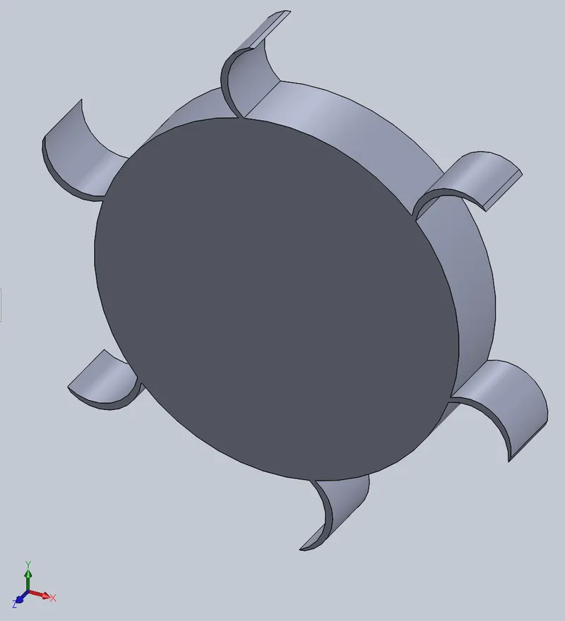
The outer radius of the impeller is 70 mm, the inner radius of the impeller is 50 mm and we have drawn the blade with a random angle and radius of curvature. By the help of the circular sketch pattern, we have designed 6 blades on the impeller. We have extruded the impeller on the midplane about a thickness of 20 mm.
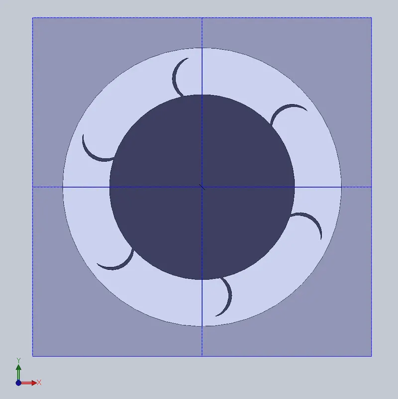
Now we have selected the same plane on which the impeller has been designed and the size of the casing is a radius of 75 mm and the thickness of 25 mm over the midplane. While we extrude the casing make sure we have to un-tick the box of the merge results.
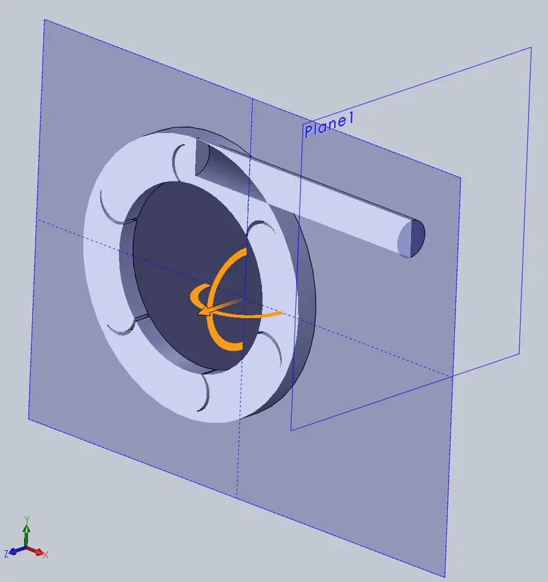
The inlet pipe is of length 250 mm and a radius of 30 mm is drawn on the impeller plane.to design the outlet pipe first we have to draw a tangent to the casing from center by a dotted line and draw another line parallel to the dotted line of length 150 mm at an offset distance of 10 mm. now go to features and click on the reference plane and click on the plane and select the line as a first reference point and the endpoint of the line as another reference point for the plane. Now draw the circle on the new plane with the line as the reference axis and dotted line as the radius of the circle (ie. 10 mm) and go to features and select the sweep boss and sweep the line over the axis. While sweeping untick the merge results option. And if we go to section view, we observe there is an overlap of the casing with outlet pipe. Now we have to go to “DIRECT EDITING” option click on “COMBINE” and select the boss extrude 3 and sweep and select add as the bullion operation. Now go to features and click on shell and select the inlet and outlet pipes and the shell thickness of 1 mm. Therefore, the whole casing, inlet, and outlet pipe have now become a single casing. To make the design hollow go to features click on shell and select inlet and outlet of the body to make it hollow/shell.
overlap figure
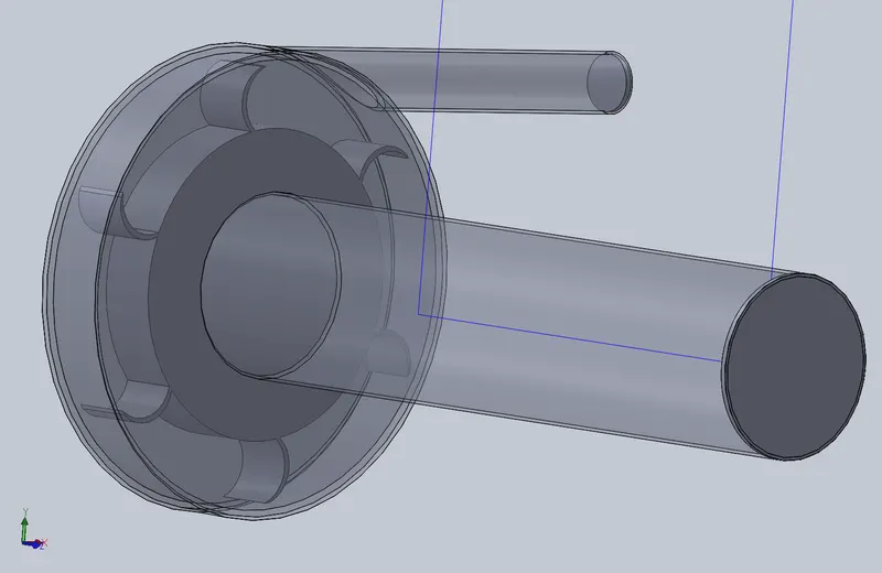
In solidworks the meshing is not able to compute the analysis of the impeller therefore with the help of the moving frame approach we have to create an imaginary volume/zone over the impeller of the radius 72 mm and the thickness of the boundary is 21 mm. before we create the zone for the better view we have to make the casing transparent.
final design
2. CFD ANALYSIS:
Now save the design. create lids on both inlet and outlet to convert the design to a control system. Go to the flow analysis tab click on the wizard and set up the analysis and select the rotation and water as the working fluid it will automatically set the computational domine.
Right-click on input data click on component control and un-tick the boss extrude 4(imaginary boundary layer) and click on ok.
Now right click on rotating region and insert rotating region select boss extrude 4 and set the rotation speed to 1000 rad/s and click ok.
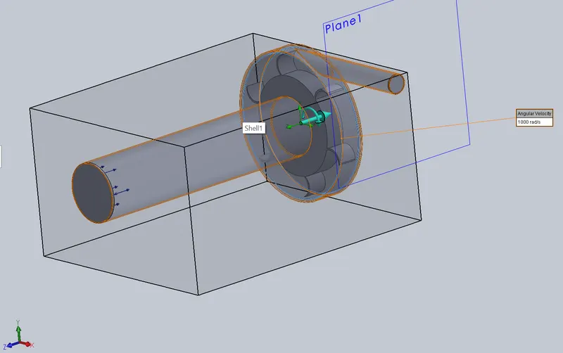
Set boundary conditions by right click on boundary conditions and click on insert boundary select the inlet face and give the environmental pressure as the boundary and select the outlet face and giving the outlet velocity as 10 m/s and click ok.
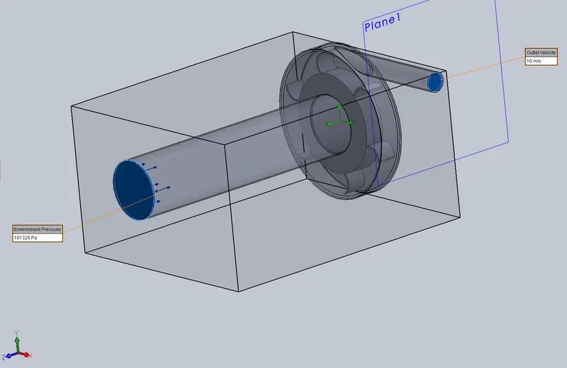
Now set the goals to right-click on goals and click on insert goals and set the goal to be outlet average of total pressure.
Set the mesh, right-click on the global mesh and click on edit global mesh and select the mesh size to 6 and tick the advanced mesh box.
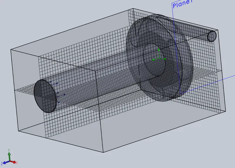
For a better explanation of results, create cut plots one for velocity, other for pressure, and also define flow trajectory for a better understanding of the flow.
3. PAMERAMETRIC STUDY:
INPUTS:
Take variable velocities from 10 to 30 m/s. here we have taken 5
Ex: 10,15,20,25,30 m/s.
OUTPUTS:
Total pressure and mass flow rate at the outlet of the pump. And velocity and pressure construe on the right side plane.
GOAL:
Is to plot a curve between total pressure and mass flow rate at the outlet.
RESULTS AND EXPLANATIONS:
Here pumps are energy converting machine with converts kinetic energy to pressure head. This conversion is done by the impeller when the impeller is rotating the fluid is sucked in due to low pressure created by an impeller and the blades of the impeller compress the fluid against the casing to increase the pressure.
If the mass flow rate of discharge is high then the pressure will be low.
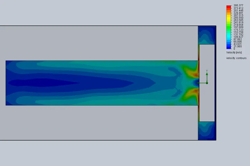
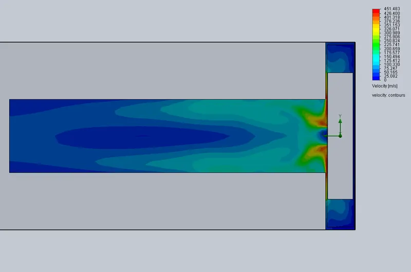
VELOCITY CONTRUE: PRESSUR CONTRUE:
At velocity 10 m/s:
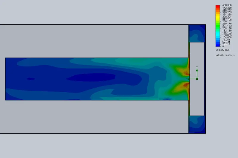
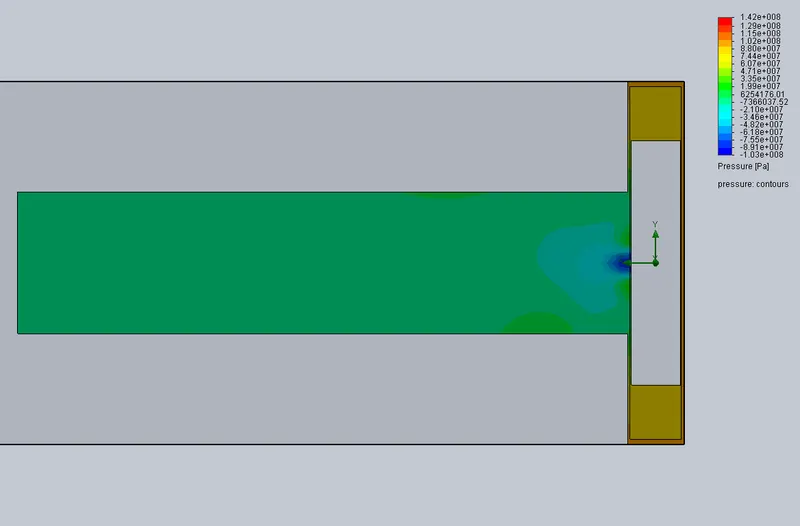
At velocity 15 m/s:
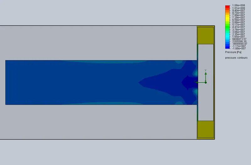
At velocity 20 m/s:
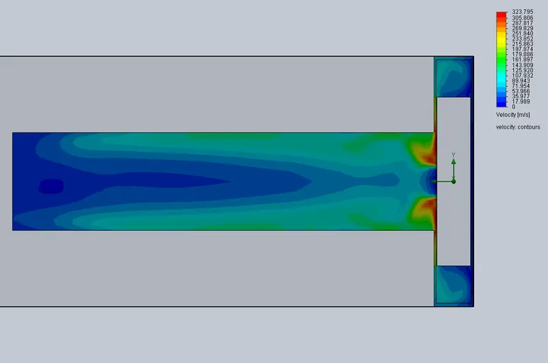
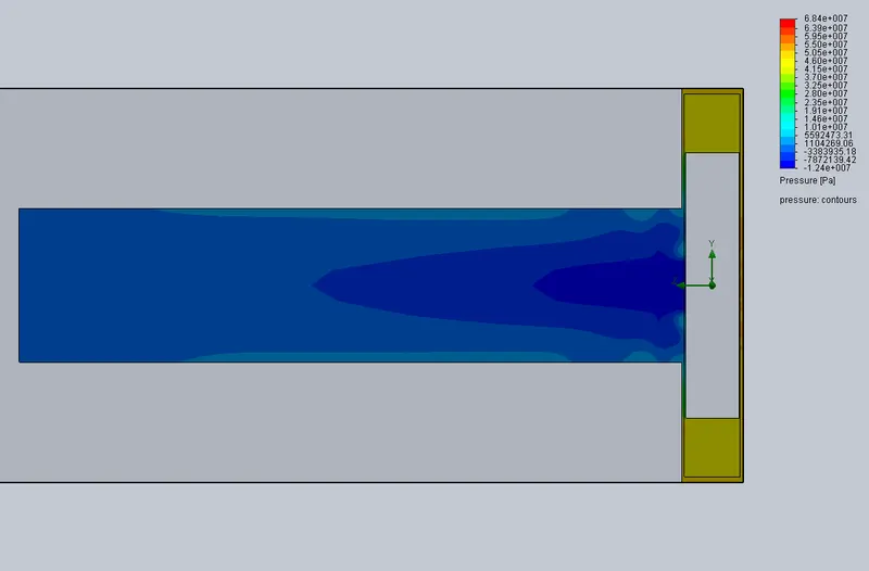
At velocity 25 m/s:
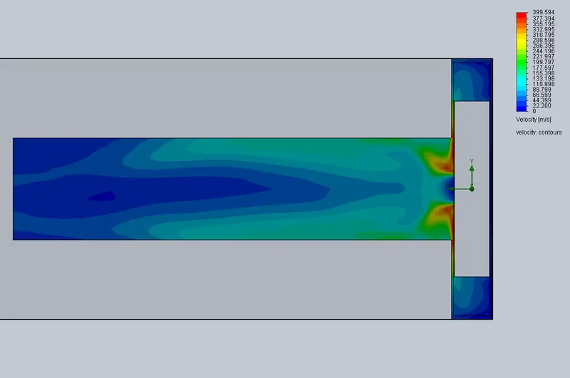
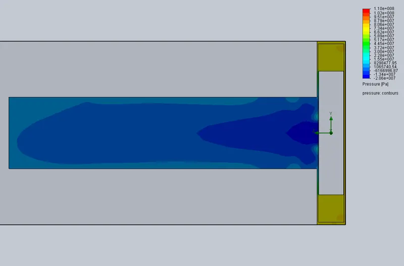
At velocity 30 m/s:
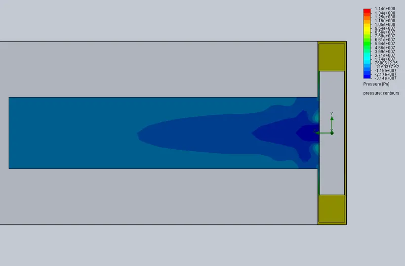
sample:at v=10 m/s.
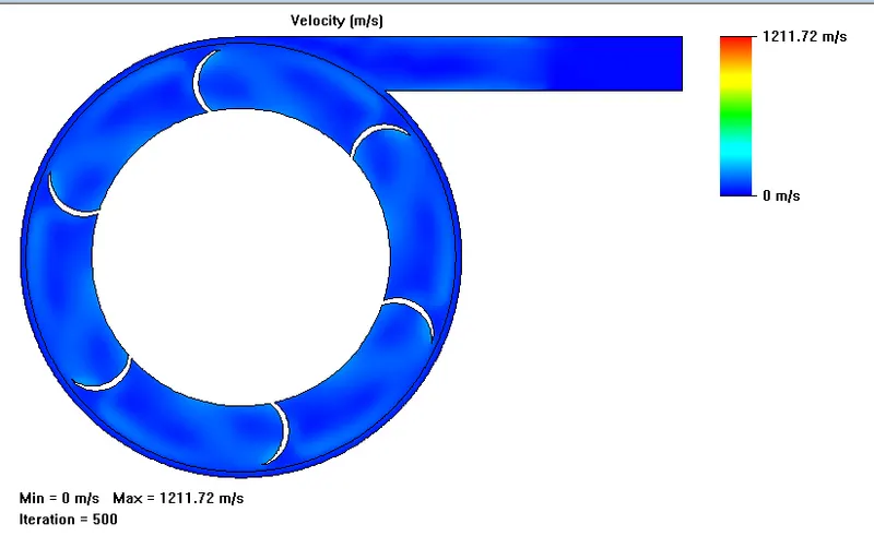
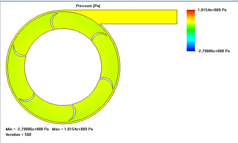
Animation of flow trajectory: Pressure variation in Centrifugal pump with flow trajectory
https://drive.google.com/file/d/1ydd0knWOE-uBppeNQ2-ZMOzYmfUWqNQP/view?usp=sharing
PLOTS:
| Goal (Value) | Design Point 1 | Design Point 2 | Design Point 3 | Design Point 4 | Design Point 5 |
| Velocity normal to face (Outlet Velocity 1) [m/s] | 10 | 15 | 20 | 25 | 30 |
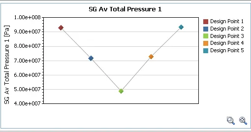
| SG Av Total Pressure 1 [Pa] | 92967224.76 | 71730743.87 | 48961632.6 | 72943195.6 | 93513002.04 |
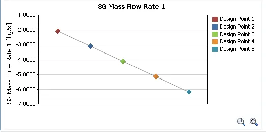
| SG Mass Flow Rate 1 [kg/s] | -2.053710571 | -3.080565856 | -4.107421142 | -5.134276427 | -6.161131713 |
| Environmental Pressure [Pa] | 101325 | 101325 | 101325 | 101325 | 101325 |
| Pressure Ratio | 917.5151 | 707.9274 | 483.2137 | 719.8933 | 922.9015 |
VELOCITY VS PRESSURE: VELOCITY VS MASS FLOW RATE:
PRESSURE RATIO VS MASS FLOW RATE:
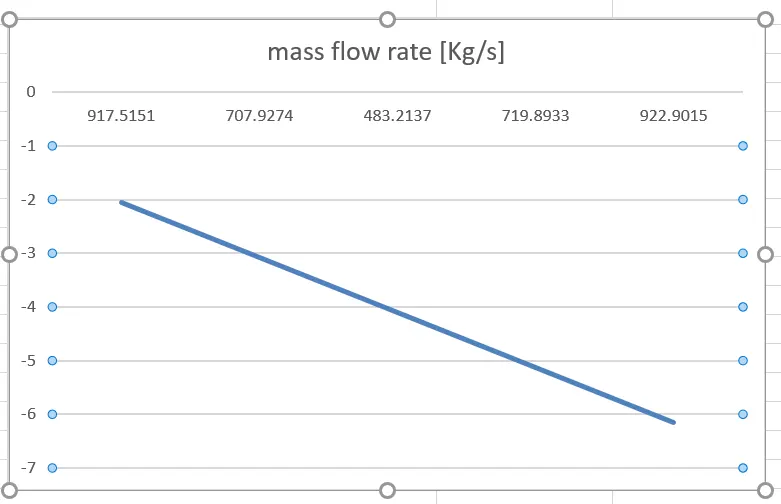
Therefore the mass flow rate is directly proportional to the pressure ratio. They have a linear relation.