Flow over an airfoil
AIM:
For the angle of attacks 0,2,4,6,8,10 compare the lift and drag forces for the airfoiled model the flow over a NACA0017.
INTRODUCTION:
The airfoiled shape is communally used in flites. The wings of the airplane are in this shape to provide different lift and drag forces. These forces help the airplane to fly, decelerate the speed of the aircraft.
Ex: 1. if the lift force is greater than the drag force the body tends to fly.
- while landing to decelerate the plane the drag force must be greater than the lift force.
They use some extrusions to further increase drag force and lift force.
The angle of attack of the general plane is 15 degrees to generate a high lift force.
Show And Explain The Entire Case Setup:
- we had designed the aerofoil shape by the help of the naca0017 data file. Click on insert select the curve option import the data now the aerofoil shape is reedy now select the profile and click on convert the sketch and draw a line joining the curve.
- Now we rotate the sketch by helping with “move entities” select the rotate option now select both “curve and line” and define the point on which we have to rotate the aerofoil and now define the angle. After defining the angle of attack we then extrude the profile to a length of 10 mm.
modal at an angle of attack 0 degrees: modal at an angle of attack 2 degrees:
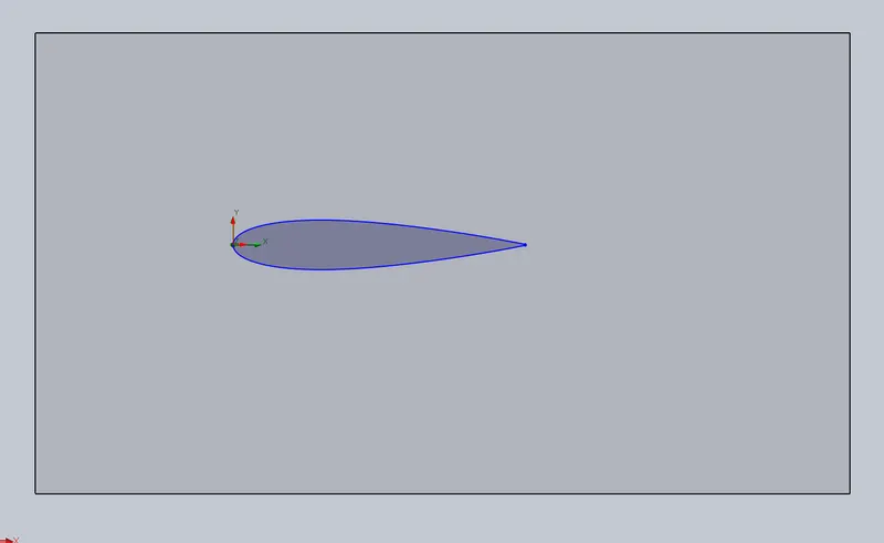
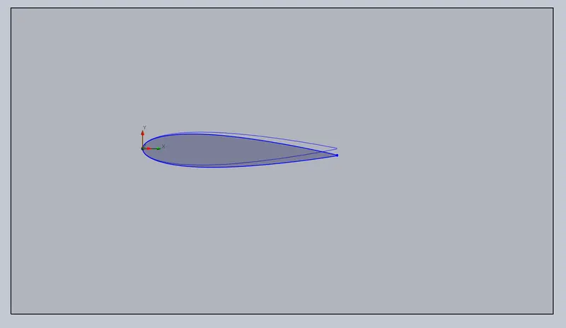
modal at an angle of attack 4 degrees: modal at an angle of attack 6 degrees:
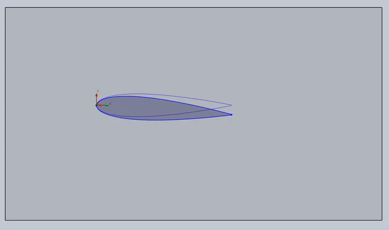
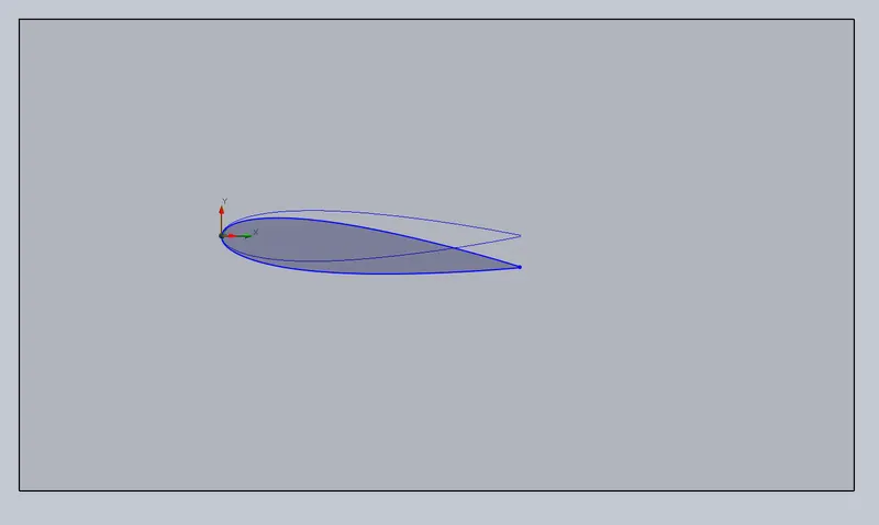
modal at an angle of attack 8 degrees: modal at an angle of attack 10 degrees:
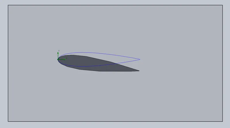
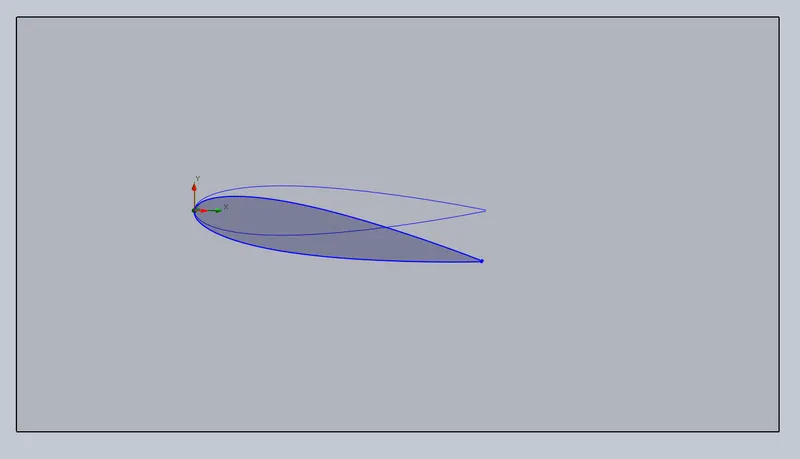
- To design go through CFD analysis we have to close the system.Now we go to wizard option to give the inputs to over-analysis.
INPUTS:
- what kind of analysis (time-dependent, temperature, etc).
- Selection of units (si, cgs, mks).
- Selection of fluids (air, water, and other chemical fluids).
- Type of flow (laminar, turbulent, both laminar and turbulent).
- Defining the initial values of fluid (velocity, temp, pressure).
- Roughness factor of the object.
Here we run a time-dependent simulation of “5 sec” and divide it into “5 different points of simulation”, and we use air as the working fluid and the velocity of 600 m/s.
- The solidworks create an imaginary cuboidal boundary around the pipe known as a Computational domine.
Right-click on “computational domine” click on “edit definition” select ‘2D analysis’. And now change the area of the computational domine by increasing its length and breadth.
Computational domine at an angle of attack 0 degrees:
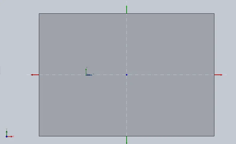
In front end at the nose of the aerofoiled shape, the length of the computational domine is “5 times” the length of the foil, and at the rare end, the length of the computational domine is “10-15 times” the length of the foil.
- We define goals, as the forces in both x and y directions.
The x-direction force is drag.
The y-direction force is lift.
- Now we mesh the aerofoil. Here solidworks will generate default mesh and we use the local mesh option at the surface of the aerofoil to get more accurate results. We can edit as we required because the finer the mesh more accurate the results are.
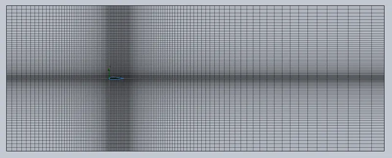
- RUN the analysis.
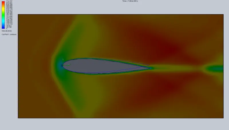
- Insert cut plot on front plane / XY plane to get the velocity profile of the aerofoil.
Results and explanation:
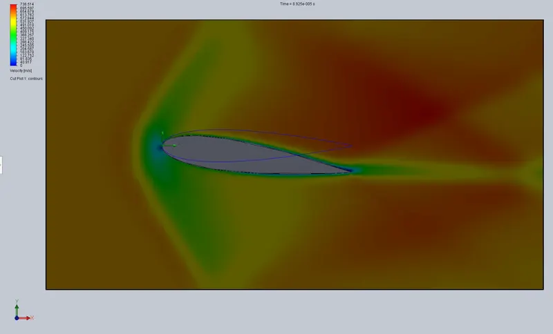
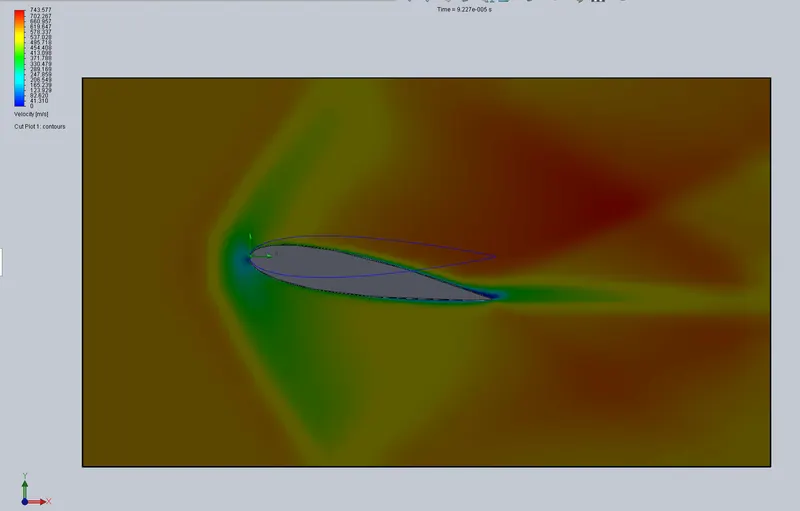
After we click on ”run” the solidworks will run a series of iterations on the computational domine to simulate the results and show us some contours.
Here we have
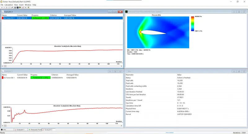
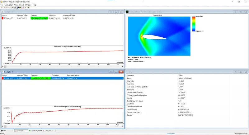
- lift force plot.
- drag force plot.
- pressure variation couture.
Here we are comparing the lift and drag forces acting on the aerofoil at a different angles of attacks.
|
Case.no |
Angle Of Attack |
LIFT FORCE N |
DRAG FORCE N |
Velocity m/s |
Max.Pressure Pa |
Min.Pressure Pa |
|
1 |
0Degrees |
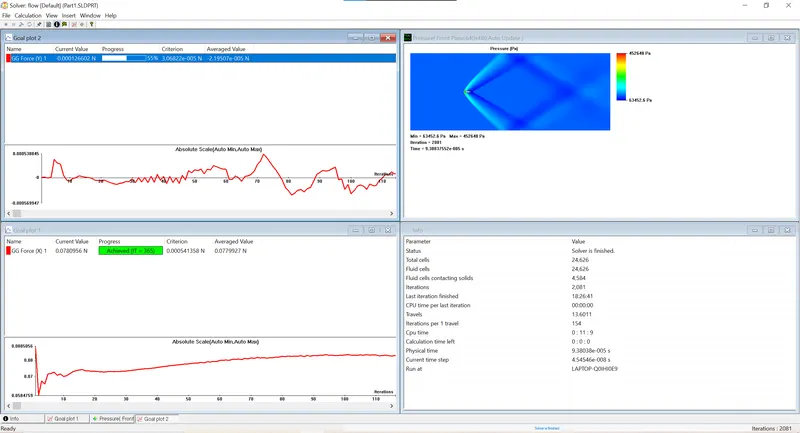
-2.9507*10^-5 |
0.0779927 |
9.7*10^-7 |
452648 |
63452.6 |
|
2 |
2 |
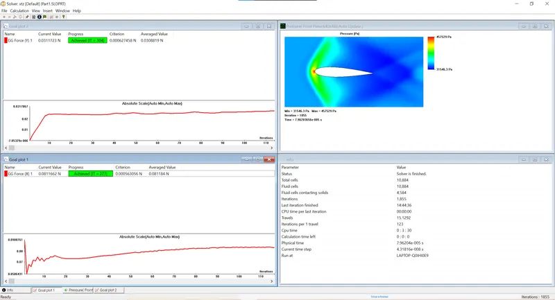
0.0308819 |
0.081184 |
714.707 |
457529 |
31546.3 |
|
3 |
4 |
0.0612067 |
0.0836715 |
721.175 |
457942 |
31011.3 |
|
4 |
6 |
0.0979251 |
0.0868754 |
724.311 |
458245 |
30349.8 |
|
5 |
8 |
0.128021 |
0.094379 |
736.514 |
453111 |
26119.6 |
|
6 |
10 |
0.161303 |
0.102739 |
743.577 |
463009 |
24995.4 |
By comparing all the above results the lift of the aerofoil will occur only when the angle of attack is equal to or greater than 6.
There is a significant change in pressure and velocity if the angle of attack is greater than 6.
Therefore by comparing all the ‘six’ cases we can come to a conclusion that the airplane will have better lift and velocity at the angle of attack is “10” and to decelerate the airplane while landing we need high drag force and low velocity at the angle of attack to be”0”.
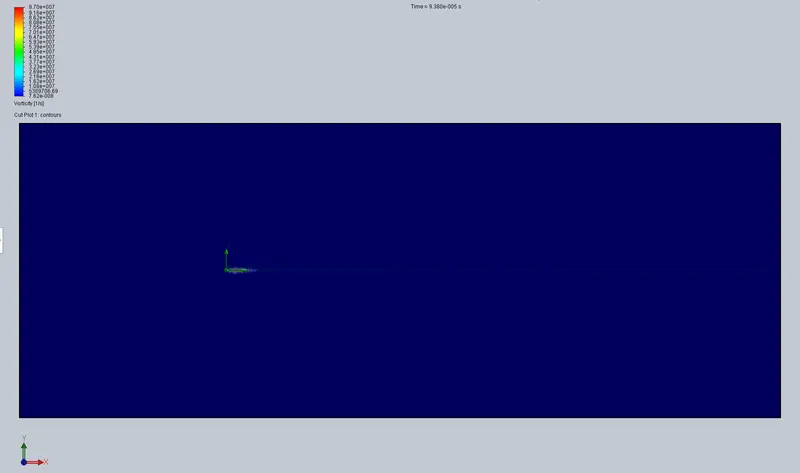
Results at an angle of attack 0 degrees: Results at an angle of attack 2 degrees:
velocity:
Results at an angle of attack 4 degrees: Results at an angle of attack 6 degrees:
velocity:
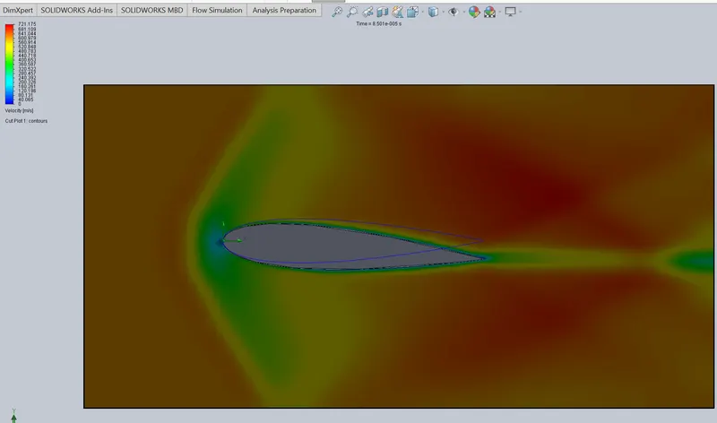
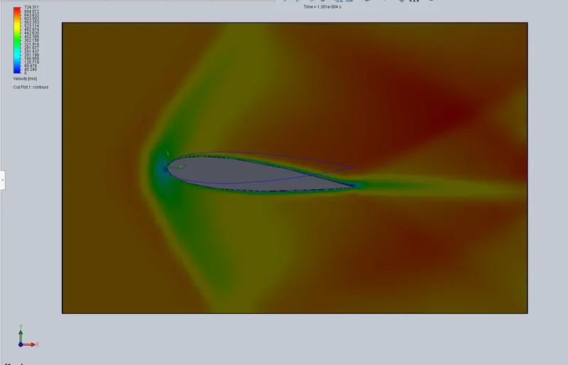
Results at an angle of attack 8 degrees: Results at an angle of attack 10 degrees:
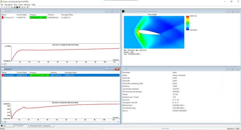
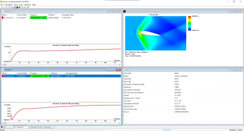
velocity: