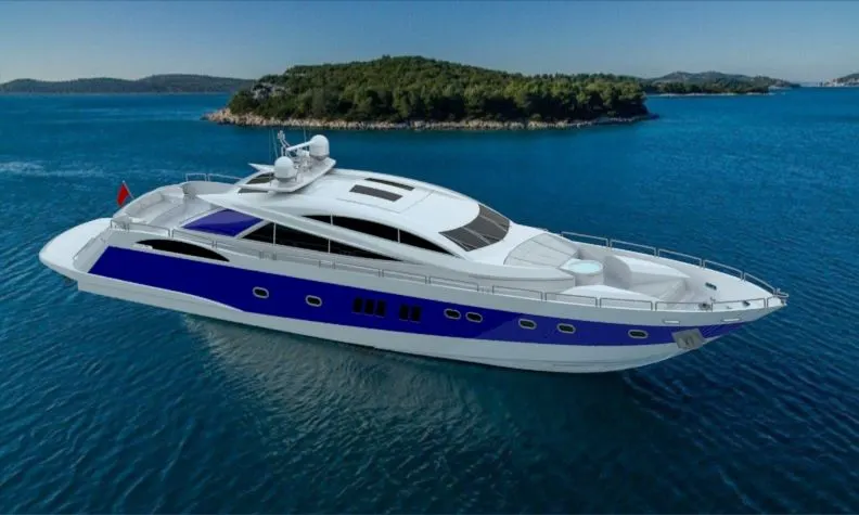
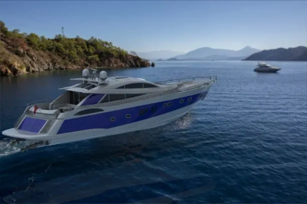
Radar Mast & Final Assembly of Yacht
TITLE: DESIGN, ASSEMBLY AND PHOTO-REALISTIC RENDERING OF AN YATCH.
OBJECTIVES: To design and model all parts of an YATCH & assembling it for creating photo-realistic rending.
INTRODUCTION:
A yacht is a type of boat which is mainly used for recreation. It usually has a cabin, so it does not need to return to the harbour overnight. Originally, yachts were sailing-boats, but now there are also motor yachts. The name comes from the Dutch word jachtschip, which originally meant hunting-boat or fast boat.
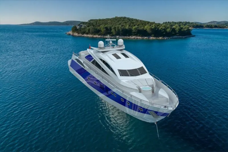
In this project the American Predator Yacht was taken as a conceptual model, to understand the 3D modelling methodology of Solid modelling and Surface modelling. Each and every part of the yacht was designed and modelled using SOLIDWORKS. Then the modelled parts were assembled by adding proper mates and constraints to create the Photo-Realistic rendered image of the Yacht.
INTODUCTION TO SOLIDWORKS:
The SOLIDWORKS is a mechanical design automation application that lets designers quickly sketch out ideas. experiment with features and dimensions, and produce models and detailed drawings.
Photo-View 360 is a SOLIDWORKS add-in that produces photo-realistic renderings of SOLIDWORKS models. The rendered image incorporates the appearances, lighting, scene, and decals included with the model.
SOLIDWORKS Visualize is a photo-realistic rendering tool that utilizes our CAD data to create magazine quality images or commercial quality animations.
DESIGN THINKING:
Design thinking is a term used to represent a set of cognitive, strategic and practical processes by which design concepts are developed.
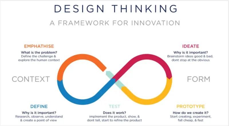
DESIGN PROCESSES:
A design process generates a conceptual solution for a problem stated in the form of requirements. The short form of the design thinking process can be articulated in five steps or phases: empathize, define, ideate, prototype and test.
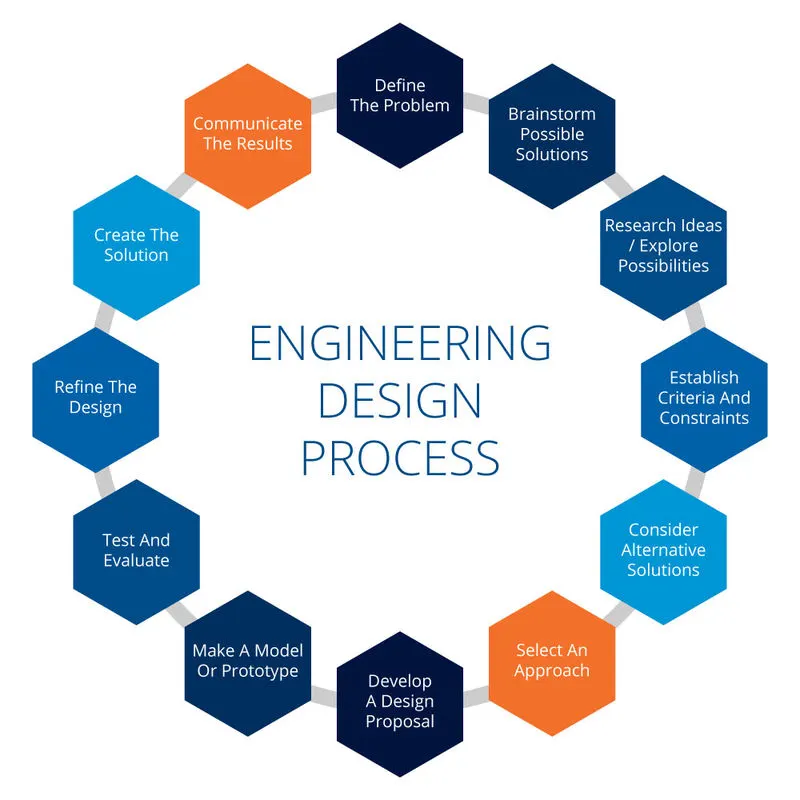
DESIGN APPROCH FOR MAKING YATCH:
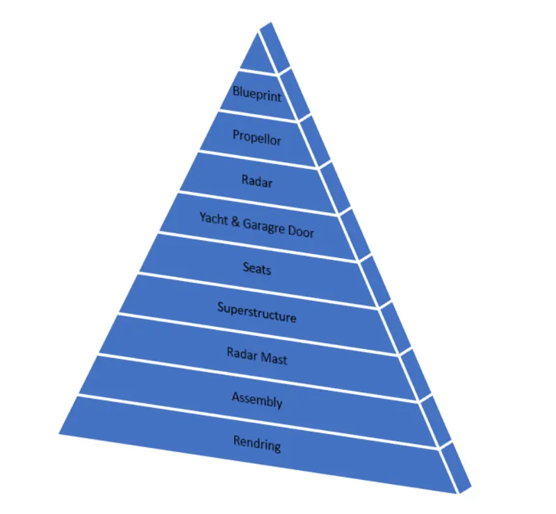
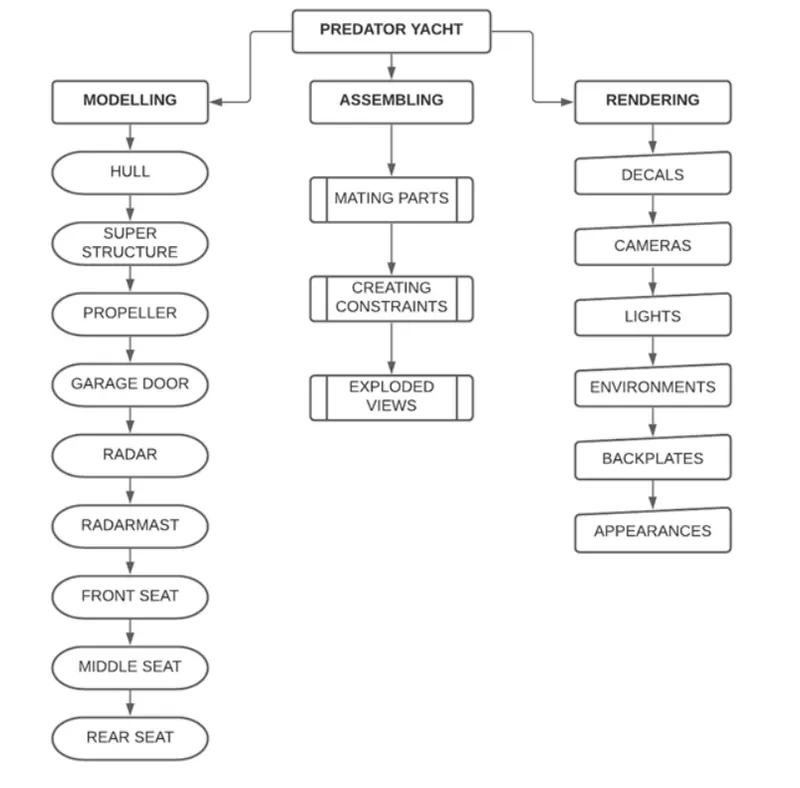
TERMINOLOGY USED:
1) ORIGIN
2) PLANE
3) AXIS
4) including intersecting two planes. The SOLIDWORKS application creates temporary axes implicitly for every conical or cylindrical face in a model.
Face Boundaries that help define the shape of a model or a surface A face is a selectable area (planar or non planar) of a model or surface.
Edge Location where two or more faces intersect and are joined together. Edges can be selected for skatching and dimenwoning
Vertext of which two or more lines or edges intersect.
TYPES OF COMMANDS USED:
1) SKETCH:
Creating a model usually begins with a sketch. From the sketch, we can create features. We can combine one or more features to make a part. Then, we can combine and mate the appropriate parts to create an assembly, From the parts or assemblies, we can then create drawings.
2) 3-D SKETCH:
When sketching in 3D, we can snap to the major directions, X, Y, or Z, and constraints are applied Along X, Y, Z respectively. These are constraints to the global coordinate system.
When sketching on a plane, we can snap to the horizontal or vertical directions in the plane, and constraints are applied to the Horizontal and the Vertical. These are constraints to a plane, planar face, etc.
SKETCH COMMANDS:
Smart Dimension - Creates a dimension for a selected sketch entity.
Line- Line is one of the first sketching tools in Solidworks Sketch Command Manager which can be drawn horizontally, vertically or at any angle. It plays very important role to complete the 2D drawing of the product or part and very easy to utilize its features.
Circle - The circle is another important sketching tool which enables to create the circular drawing or the graphics area. There are two circle tools are available and they are "Center circle" and "Perimeter circle".
Rectangle- Sketches rectangles or square with a center point at a selected angle. Parallelogram sketches a standard parallelogram.
Spline - A two or three dimensional curve defined by a set of control points. Points within a spline can be added or deleted.
Sketch Fillet- A tangent arc in between two sketch entities can be created.
Point - Inserts a point or vertex into a sketch entity. This cannot be deleted if it is part of sketch endpoint or center point
Text- It can be used to write the text necessary wherever required either it's a plane or face.
Offset Entities - Copy a sketch entity to a specified distance from the original entity. Must have a sketch entity already drawn and selected to use this tool.
Sketch Picture - Insert an image file into the background of a sketch. This allows the user to 2D sketches based off of the image. Use the sketch picture property manager to alter the inserted image
Convert Entities - Convert Entities enables you to copy model edges into your active sketch. These sketch elements are automatically fully defined and constrained with an On Edge relation. Convert Entities is like Offset Entities except that the offset distance is always zero.
FEATURE COMMANDS:
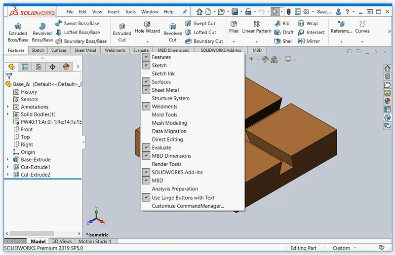
Some sketch-based features are shapes such as bosses, cuts, and holes. Other sketch-based features such as lofts and sweeps use a profile along a path. Another type of feature is called an applied feature, which does not require a sketch Applied features include fillets, chamfers, or shells. They are called "applied because they are applied to existing geometry using dimensions and other characteristics to create the feature. Typically, we create parts by including sketch-based features such as bosses and holes. Then we add applied features. It is possible to create a part without sketch-based features.
Extruded Boss/Base - One of the oldest commands in the SOLIDWORKS software is the boss/base extrude command. An Extruded Boss/Base feature will allow us to take a 2D sketch and add thickness to it in the third dimension.
Extruded Cut-It's a tool to remove material by projecting a sketched section normal to the sketching plane.
Split - Lines are used to divide model faces into two. Split lines are created like any other sketched feature. They can be one or more connected sketch entities. They must be oriented so that they will pass through model faces when projected normal to the sketch plane.
Dome- It can add one or more domes to the selected planar or non-planar faces. The software calculates the distance using the radius of the arc as a basis for the dome.
Pierce Relationships - The Pierce relationship is used in sweeps. It can be thought of as a 3D Coincident relationship.
Project Curve - Select Bi-directional to create a projection that extends on both sides of the sketch. The curve can be used as a path for a sweep.
Composite Curve - We can create composite curves by combining curves, sketch geometry, and model edges into a single curve. Composite curve can be used as a guide curve when creating a loft or a sweep.
Wire Frame -Wireframe is a view mode in which all edges of the part or assembly are displayed.
3-D MODELLING:
3D modelling is the process of developing a mathematical representation of any surface of an object (inanimate or living) in three dimensions via specialized software. The product is called a 3D model. It can be displayed as a two dimensional image through a process called 3D rendering or used in a computer simulation of physical phenomena. The model can also be physically created using 3D printing devices. In terms of game development, 3D modelling is merely a stage in the entire development process.
Models may be created automatically or manually. The manual modelling process of preparing geometric data for 30 computer graphics is similar to plastic arts such as sculpting.
3D modelling software is a class of 3D computer graphics software used to produce 3D models. Individual programs of this class are called modelling applications
The 3D part is the basic building block of any large scale design. Features are the individual shapes that when combined, make up the part. We can also add some types of features to assemblies. Part documents can contain multiple solid bodies that we can manipulate the same way as single solid bodies.
SURFACE MODELLING:
Surface modelling is a method of creating planar or non-planar complex geometry which has zero thickness. This zero thickness geometry is known as surface. The surfaces are generally used to create models of complex shapes. We can convert surface models in solid models. We can also extract a surface from a solid model using the tools available for surface modeling.
SURFACE COMMANDS:
Lofted Surfaces - Creates a lofted surface between two or more profiles or sketches. Specify start and end constraints and add guide curves to control the path shape.
Boundary Surfaces - The boundary surface feature lets us to create surfaces that can be tangent or curvature continuous in both directions (all sides of the surface). In most cases, this delivers a higher quality result than the loft tool.
Extruded Surfaces - Extrudes a sketch or selected sketch contours in one or two directions two create a surface features.
Revolved Surfaces - Revolves a sketch or selected sketch contours around an axis to create a surface features • Swept Surfaces It Sweeps a closed profile along an open or closed path to create a surface feature. It uses a tangent plane at the end of the path so that the path is normal to the swept surface.
Filled Surfaces - Patches a surface within a boundary defined by edges, sketches, or curves. We can use constraint curves to fill surfaces and adjust resolution control to improve surface finish.
Ruled Surfaces - Inserts ruled surface in a specified direction from edges Tangent to surface, Normal to surface, tapered to vector, perpendicular to vector or sweep can be selected. We can also trim and knit the surfaces and remove any connecting surfaces.
Trim Surface - It trims the surfaces where a surface intersect with another surface, a plane or a sketch • Knit Surface-It combines two or more adjacent, non-intersecting surfaces into a single surface body. The surfaces must joint at an edge. If the resulting knit surface encloses a volume, we can create a solid body from the Property Manager
Move/copy surfaces - Moves or copy surfaces about a plane or a sketch.
Offset Surface- Offsets surfaces using one or more contiguous faces. This tool helps us to create an offset surface with gaps.

PART MODELLING:
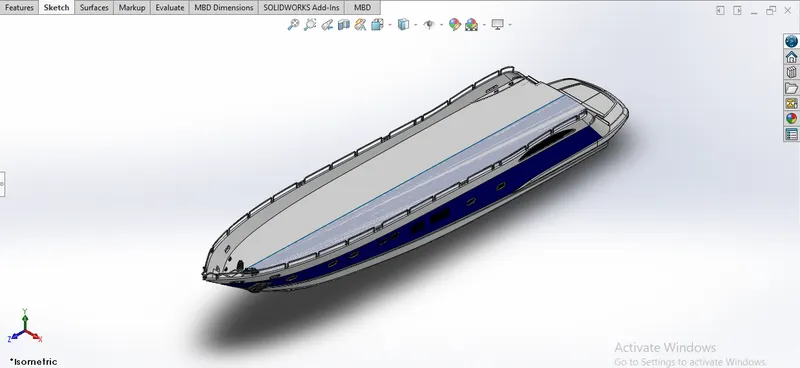
1) HULL: A hull is the watertight body of a ship, boat, or flying boat.
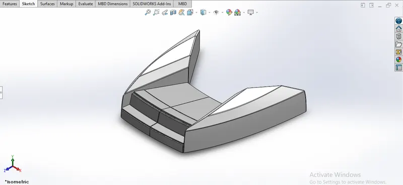
2) FRONT SEATS:
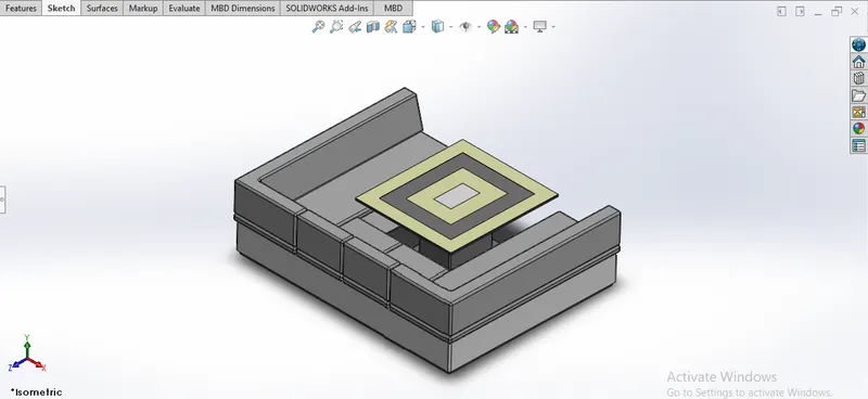
3) MIDDLE SEATS:
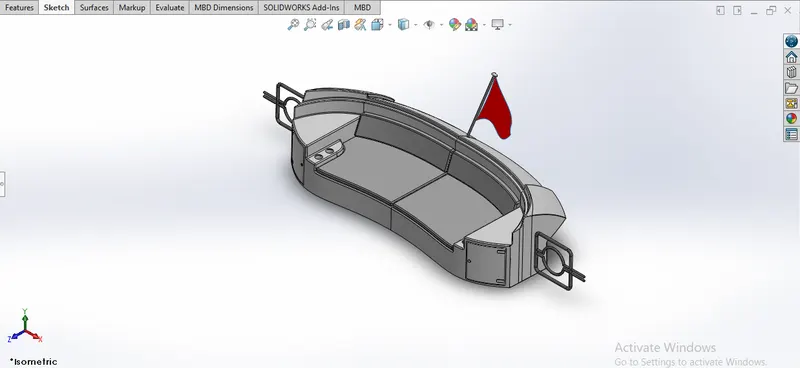
4) REAR/BACK SEAT:
5) GARAGE DOOR:
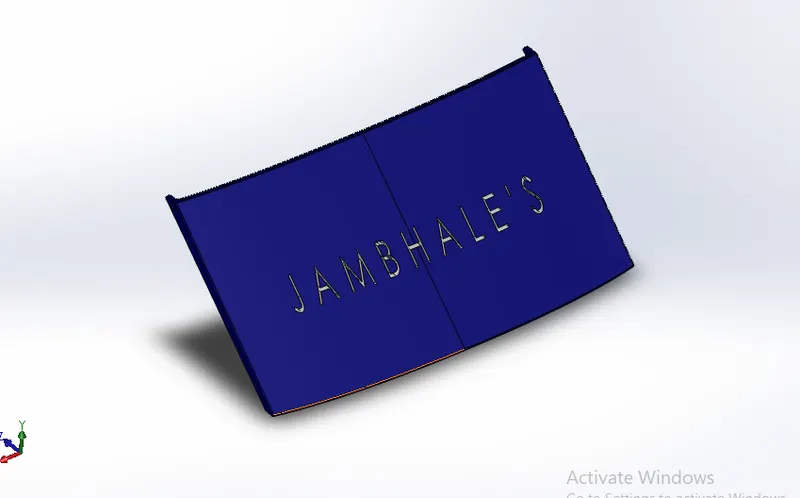
6) SUPERSTRUCTURE:
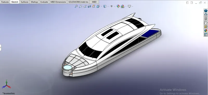
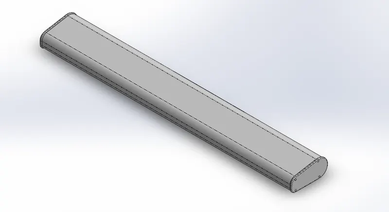
7) RADAR-MAST:
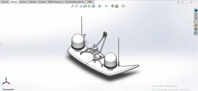
8) PROPELLER:
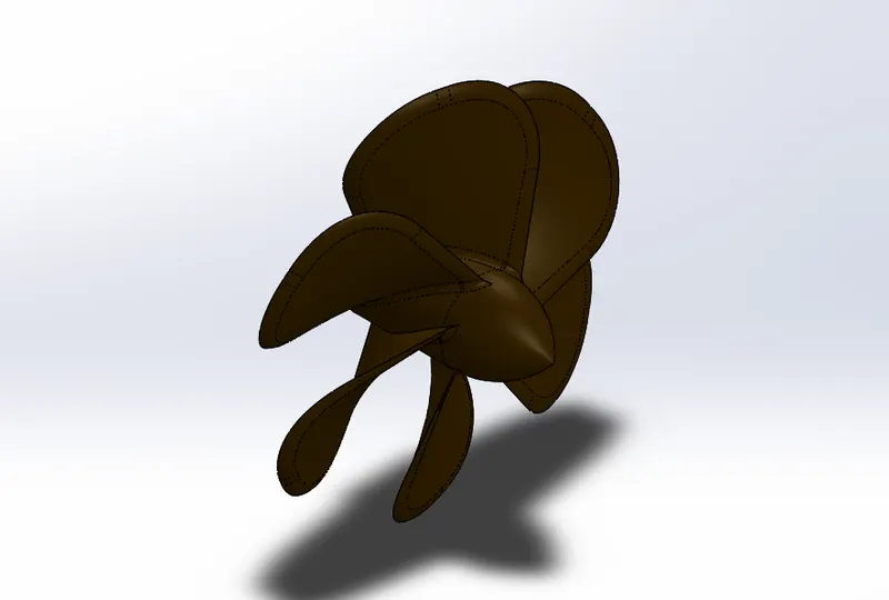
9) RADAR:
ASSEMBLY:
An assembly is a document in which parts, features, and other assemblies (sub-assemblies) are mated together. The parts and subassemblies exist in documents separate from the assembly. For example, in an assembly, a piston can be mated to other parts, such as a connecting rod or cylinder. This new assembly can then be used as a sub assembly in an assembly of an engine. The extension for a SolidWorks assembly file name is SLDASM.
ASSEMBLY COMMANDS:
- Smart Mate
- Mate
- Mate Group
- sub-Assemble
RENDERING:
Rendering of the Solidworks model is done using PhotoView 360 and Solidworks Visualize
PhotoView 360 is a visualization and rendering solution included with SOLIDWORKS. Providing a highly interactive environment for viewing designs as well as for creating photo-realistic renderings it can be used to showcase our designs.
SOLIDWORKS Visualize (formerly known as Bunkspeed) provides a suite of standalone software tools that combine industry-leading rendering capabilities with visual design-oriented features and workflows, allowing easy and fast creation of visual content that communicates a design's vision, passion, and emotion.
PhotoView 360 is a software package, separate to Solidworks, which generates digital elke ages (photorealistic Images) from SolidWorks files. PhotoView 360 is an easy and quick way to produce high quality photorealistic images.
Environments-Environments can be looked upon as backdrops and can be applied in a similar manner as the appearances are applied to faces or parts.
Appearances - There are a wider range of appearances in PhotoView 360 than in SolidWorks if we wish to change an appearance just drag and drop the chosen appearance onto the part and it will replace the existing one.
Lighting- Lights may be added in the same way a photographer adds lights when taking photographs, PhotoView 360 uses the same lights as SolidWorks but also uses lighting from the rendering environment or scene PhotoView 360 has the sophistication to trace light rays and reflections.
Scenes Each SolidWorks model is associated with a PhotoView 360 scene, for which you can specify properties such as environments and backgrounds. Scenes help to put products in context Decals - Images, such as company logos, can be applied to models.
Output -The rendered output from PhotoView 360 can be viewed on the screen, or saved to a graphics 106 • Options PhotoView 360 has its own options. Options allow you to customize the Photoview 260 settings to fit your preferences. Options are divided into Output Image Settings, Render Quality, Bloom Contour Rendering and Direct