Radar Mast & Final Assembly of Yacht
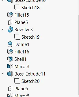
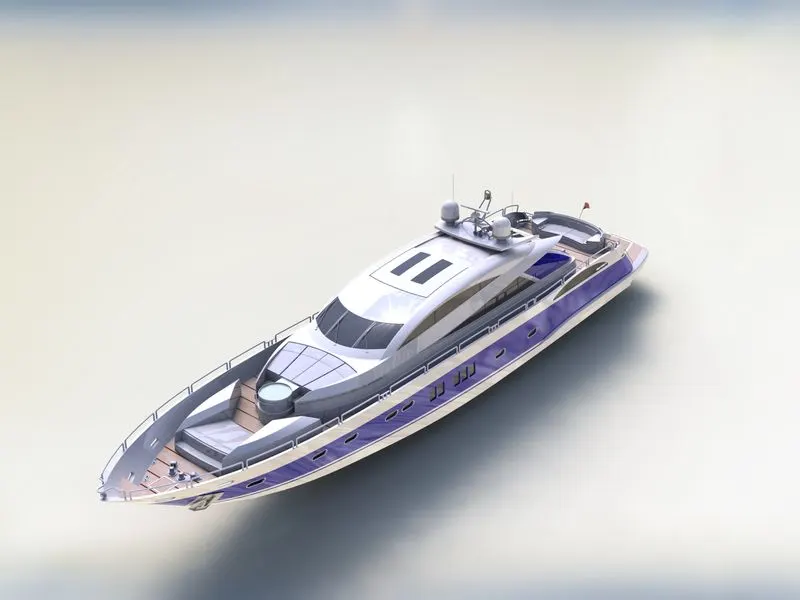
MODELING OF SUNSEEKER PREDATOR YACHT ON SOLIDWORKS
INTRODUCTION
In this project, we are to learn the entire moduling of sunseeker predator yacht on solid works and photo view 360.
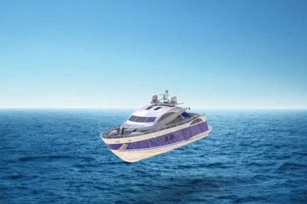
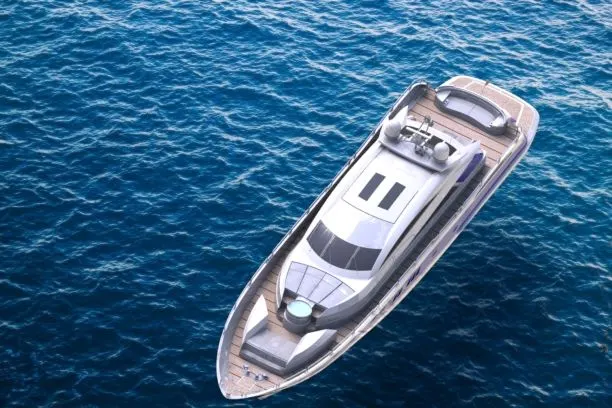
A yacht is a sailor power vessel used for cruising or exploring via sea route. It usually comes in 33ft in length and aesthetics, amenities a luxury. Medium size yachts are made from fiberglass while large yachts are made of steel, alluminium or composite fiber- reinforced plastic.
The different components of the yacht we deal with are.
1. Propellor
2. Radar
3. Hull
4. Garage and Garage door
5. Front seat
6. Rear seat
7. Middle seat
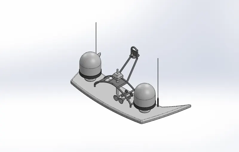
8. Radar Mast
9. Superstructure
After desinging the part components, we have worked upon the assembly and the photo rendering of the yacht which gives it a complete and realistic view.
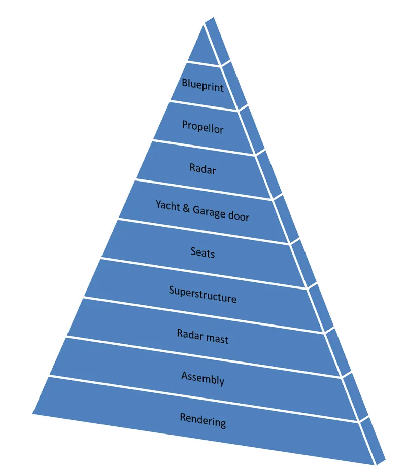
DESING APPROACH
Staring with the propellor and ending with the rendering has been discribe step by step by using flow chart.
Let's discuss what are the features and properties used in the entire model to desing diffent parts.
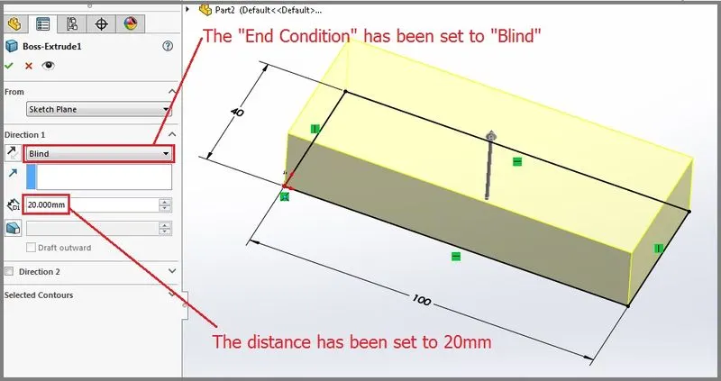
1. EXTRUDE BOSS
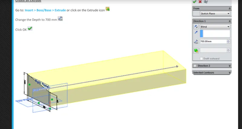
The extruded boss is the most basic of all solid works features and extrude a sketch along a staight line path to add material. As a sketched feature , it reqiure sketch before use. Once this sketch has been created, exit the sketchj and select the feature tab of thre command manager, Then click the extrude boss/ base command. If a yellow dialog box appears in the property managar asking you to create a new sketch, Don't worry- simply click on the sketch in the graphics area to use it for the feature. The property Manager for the extrude boss allows you to control the starting location, extrude path and draft for the feature among servel other parameters.
2. Fillet
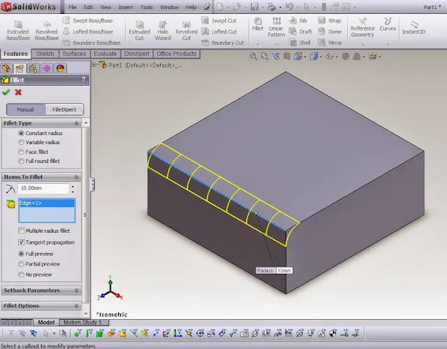
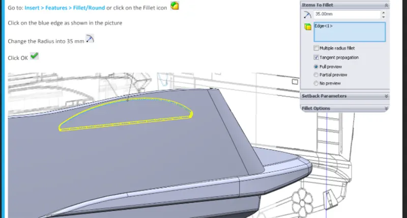
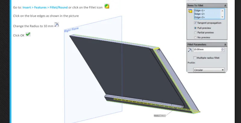
Fillets are classified as applied deatures, and as such do not require a sketch to be used. Fillets serve to round off edges or corners by adding or removing material, depending on whether the edge is internal or external. It should be noted that fillets of diffent sizes must be created as seperate features. Typically it is best practics to create the largest fillets first and follow with smaller fillets.
REVOLVED BOSS FEATURE
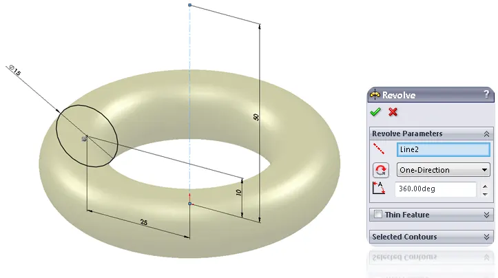
Adds material by revolving a sketch around an axis. Remember once geometry has been created in your model, any flat face can be used as a sketching surface. It is very important to draw an axis in the sketch which needs to be revolved.
3. EXTRUDE CUT
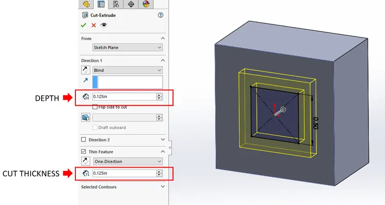
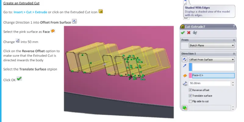
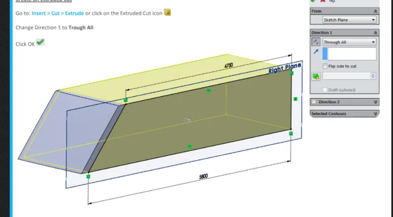
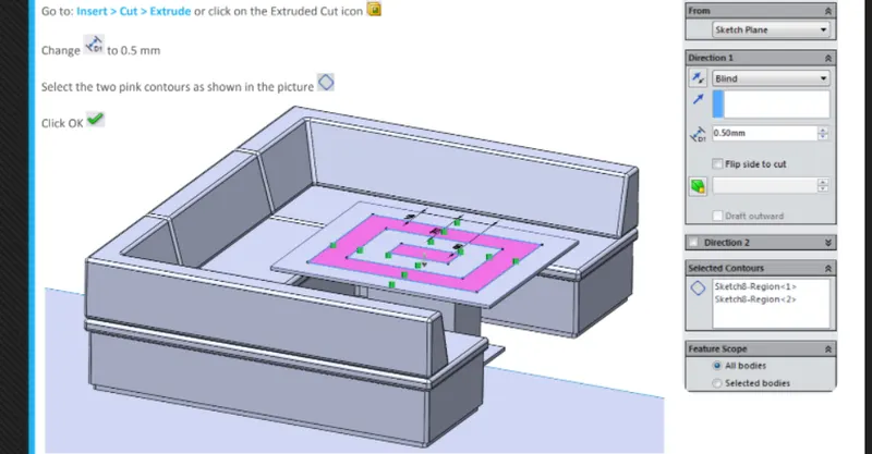
Simolar to the extrude boss feature this feature needs a sketch on the solid body which needs to be cut and desired shape is then cut off.
SHELL
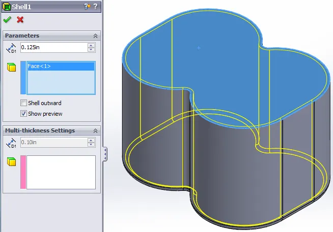
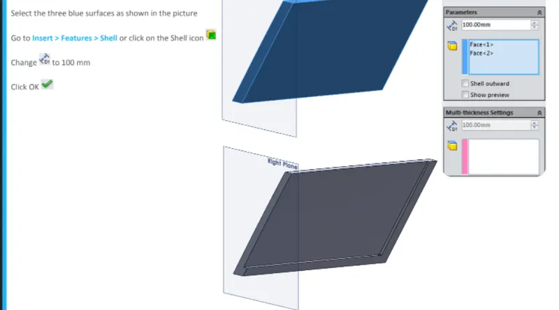
Shell tool is mainly used for the shelling process in which the material is removed from the inner body of the model by keeping small thickness and result in a hollow model. using this tool
4. SWEEP BOSS/SWEEP CUT
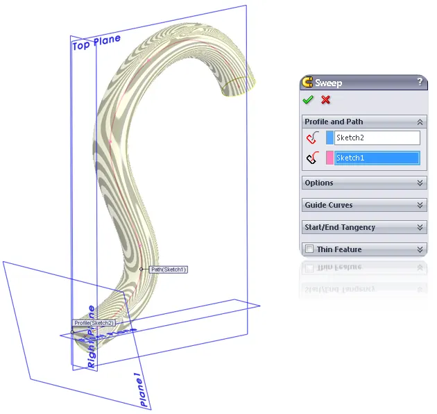
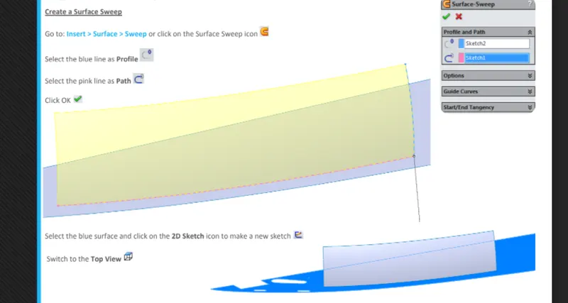
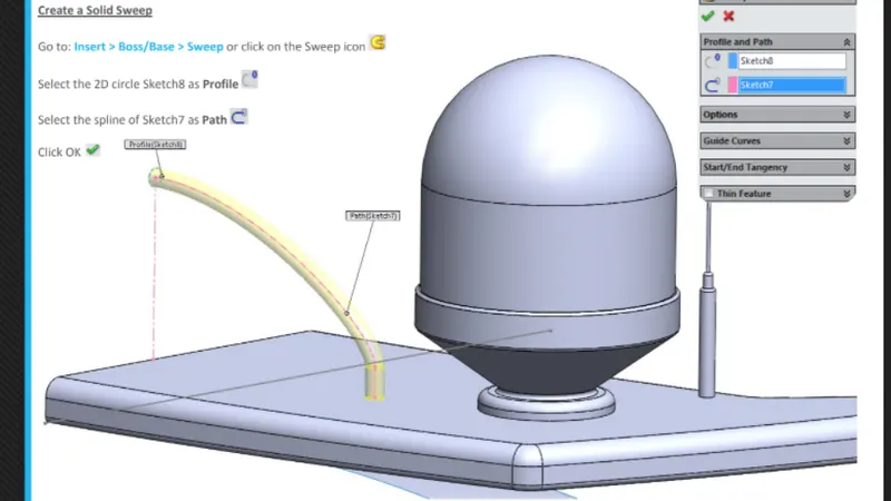
Sweep creates a baser,boss,cut or surface by moving a profile (section ) along a path, according to these rules the profile must be closed for a base or boss sweep feature, the profile may be open or closed for a surface sweep feature
LOFT BOSS/ LOFT CUT
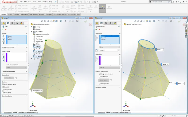
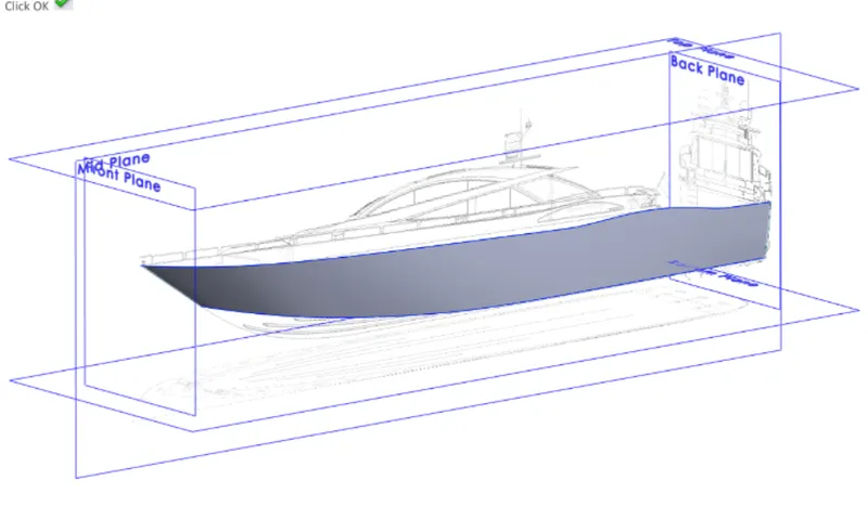
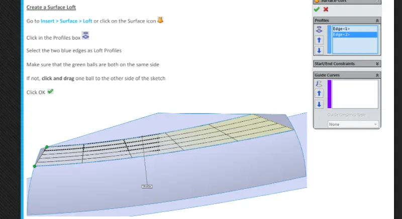
A loft feature is an importent tool for (surface) modeling in solidworks. The loft feature creates a shape by making transition between multiple between multiple profiles and guide curves. This tool is very valuable for modeling complex surfaces. You can do some cool stuff when you use this feature properly.
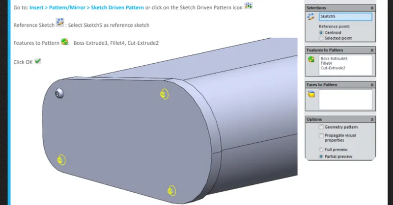
LINEAR PATTERN you can use linear pattern to create multiple instances of one or more feature that you can space uniformely along one or two linear paths. 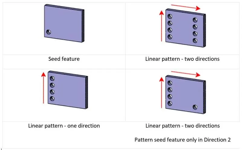
MIRROR
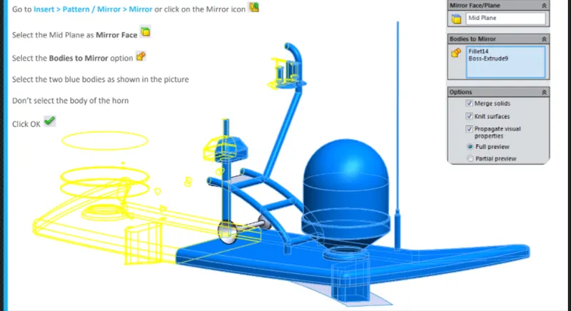
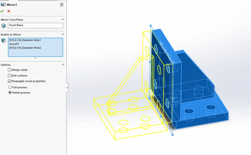
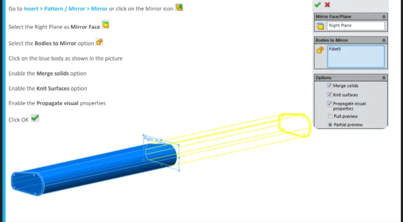
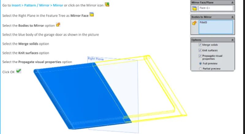
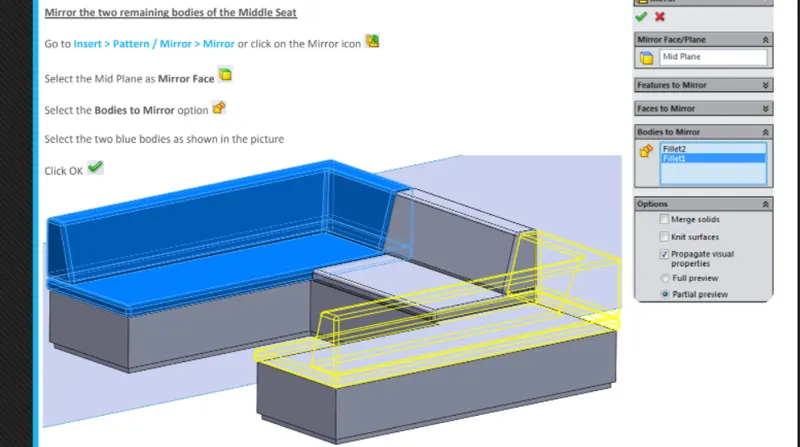
create a copy of a feature, mirrored about a face or a plain. you can select the feature mirrored about a faace or plain. you can select the feature or you can select the face that comprises the feature. bodies to mirror select the body in a single model and multi body part to create a mirror entity
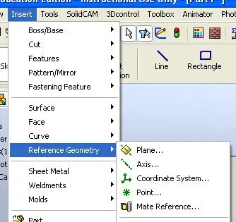
REFERENCE GEOMETRY
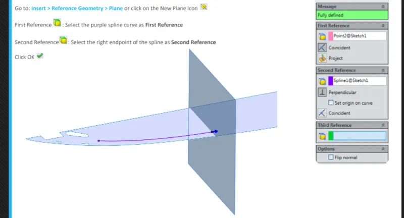
reference geometry defines the shape or form of a coordinate systems, and points. you can use reference geometry in the creation of several kinds of features. for example planes are used in lofts and sweeps,an axix is used in circular pattern
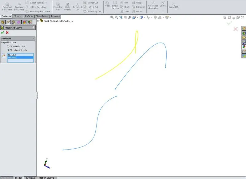
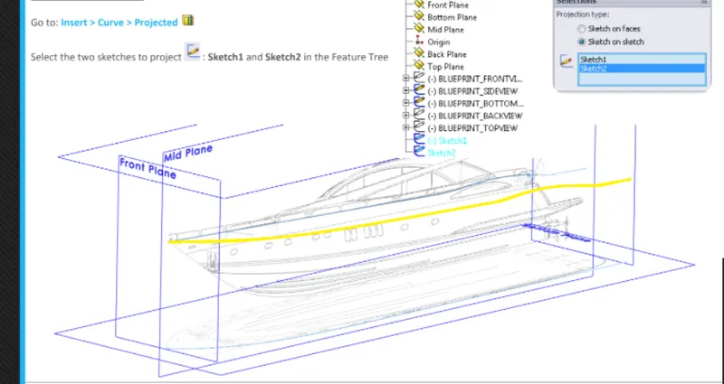
PROJECTED CURVE
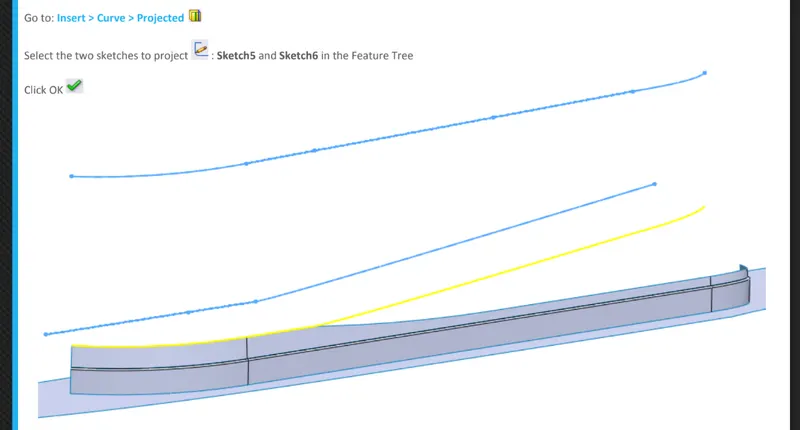
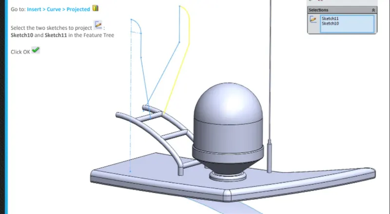
ypo can project a sketched curve onto a model face to create a 3d curve that represents the intersection of two extruded surfaces genereted by creating sketches on two intersecting planes
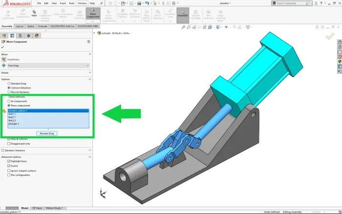
MATE
mates creates geometric relationship between assembly components. as you add mates, you define the allowable diractions of linear or rotational motion of the components. you can move a component within its degrees of freedom,visualizing the assembly's behavior
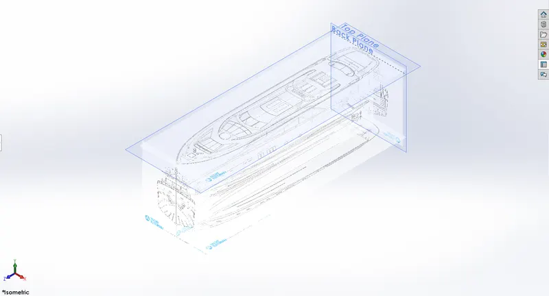
SETTING UP BLUEPRINT
Blueprint were inported by following path. tools_sketch tool_sketch picture. then diamension was given to the position the blueprint according to the planes. the setup was uesd to create all the components of the yacht
PROPELLOR
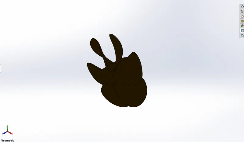
the solid body consist of fan blades mounted on hollow cylinder of certain thickness the maine function of the propellor is to generate the thrust by rotating of fan blades so that the yacht can move forward the following features are uesd to create the solid geometry
first we create a hollow cylinderical shape hub of the propellor by using revolve tool then after selected the outside surface of the hub and draw a 2d sketch rectangle.one more 2d sketch rectangle is created on new reference plane and use the feature lofted boss base to creare a curved shape blade of propellor, with the help of fillets and and circular pattern features the desired shape of propellor is achived
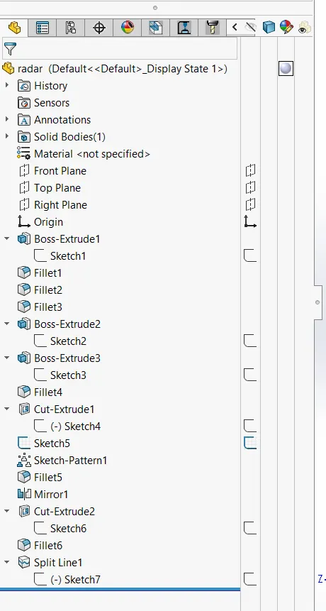
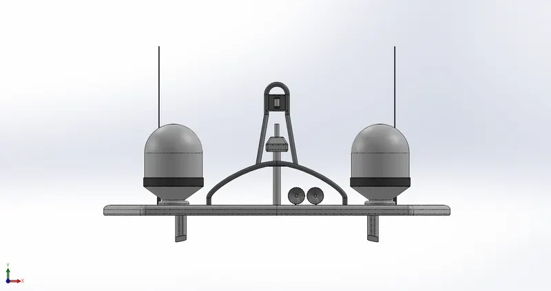
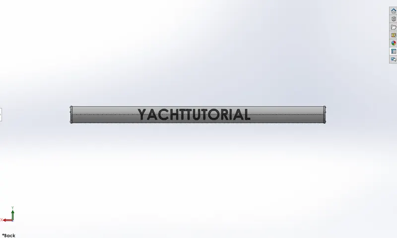
RADAR
BOSS EXTRUDE
MIRROR
SKETCH PATTERN
HULL
the hull is the main body of the yacht, all other parts such as superstructure, radar, seats are mounted on the top of the deck surface of the hull. the hull is the weighted body of the ship it carryes cargo space and machinery and acomodation spaces of the ship
following features uesd in hull
projected curve
surface loft
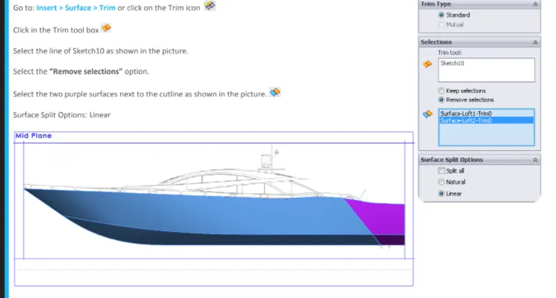
Surface trim
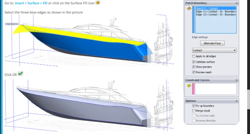
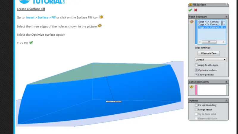
surface fill
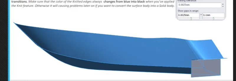
Surface knit
Fillet
Extrude cut
GARAGE DOOR
EXTRUDE CUT
SHELL
FILLETS
MIRROR
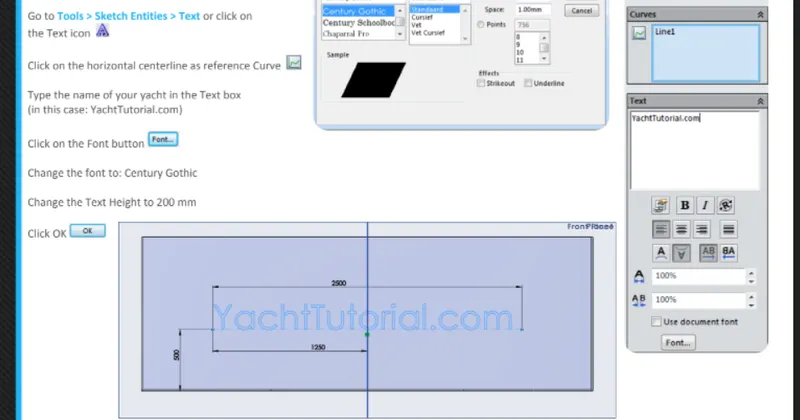
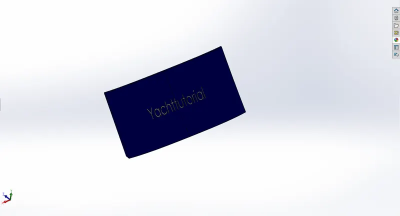
SKECTH TEXT
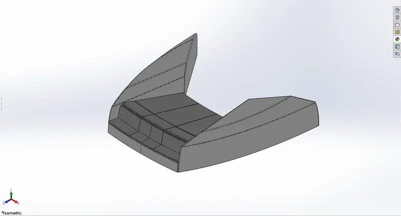
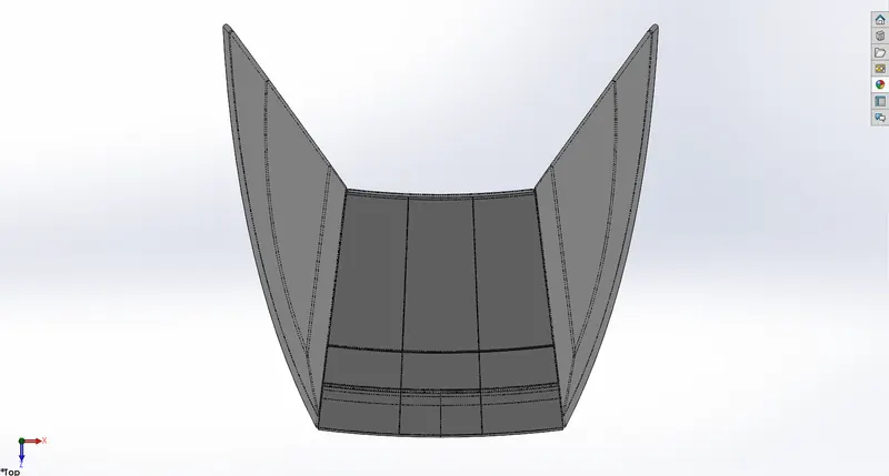
FRONT SEAT
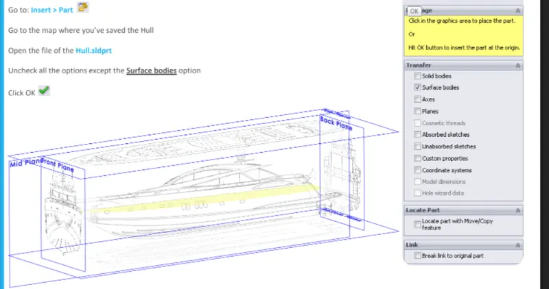
INSERT PART
REFERENCE PLANE
SURFACE SWEEP
SURFACE FILL
SURFACE LOFT
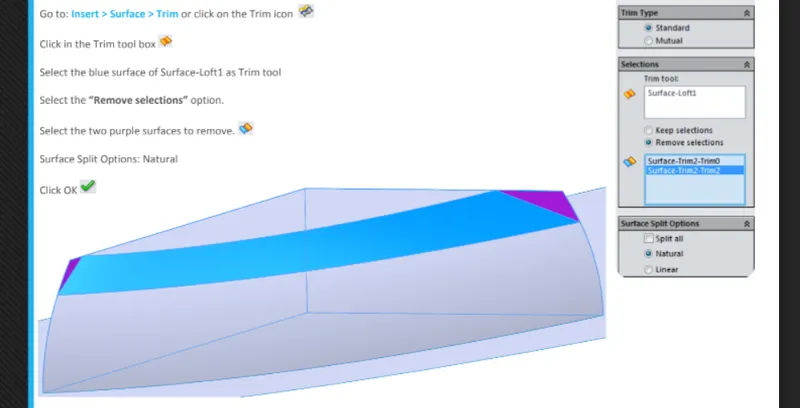
SURFACE TRIM
MIDDLE SEAT
INSERT PART
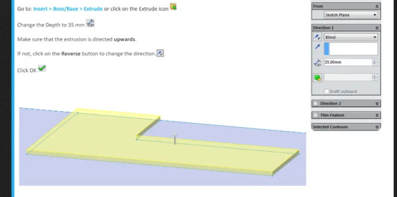
EXTRUDE BOSS/BASE
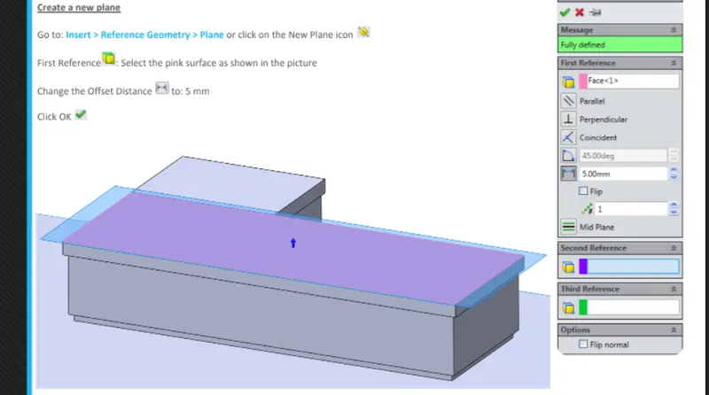
REFERENCE PLANE
MIRROR
CUT EXTRUDE
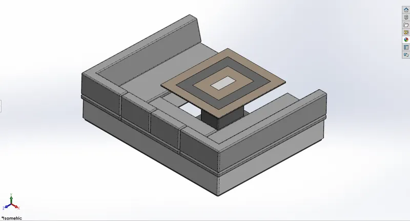
REAR SEAT
INSERT PART
SURFACE SWEEP
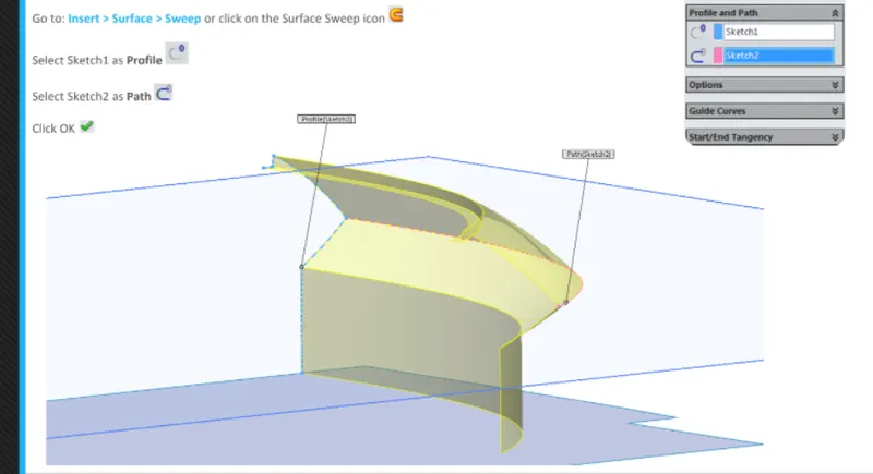
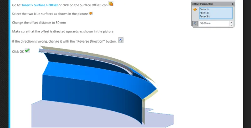
SURFACE OFFSET
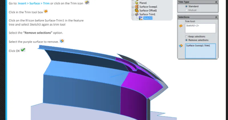
TRIM SURFACE
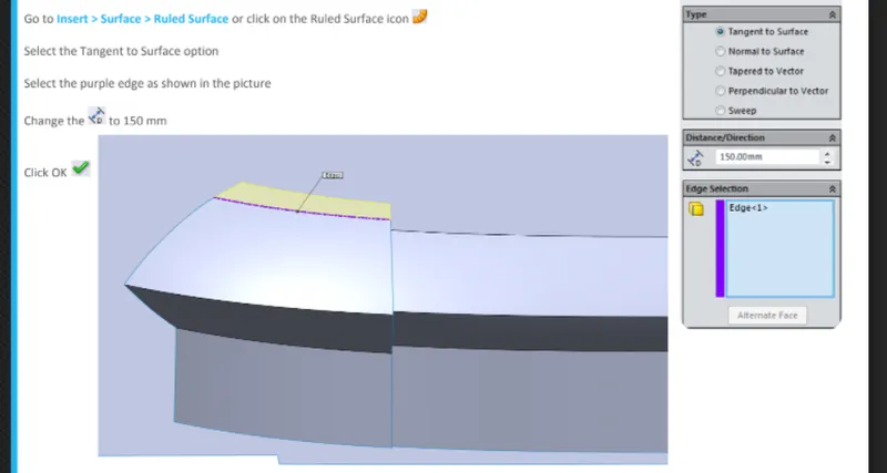
RULED SURFACE
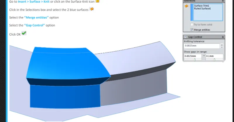
SURFACE KNIT
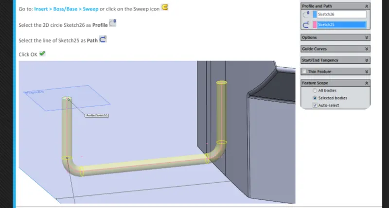
SWEEP
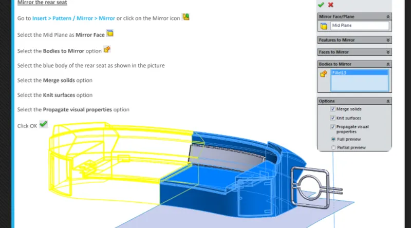
MIRROR
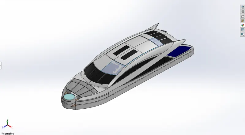
SUPERSTRUCTURE
On a watercraft superstructure consist of the part of a shop or boat that project above her main deck. This does not usually include its mats or any armament turrets. The word comes from a combination of two Latin words, the Latin prefix ‘super’ means in addition or above or in excess of, whereas the stem word ‘structure’ means to build or to heap up. Thus, superstructure means to add a construction to an already existing structure. In ships this is the name given to the part of the ship that emerges from the deck. However any mast, sails, any armaments or arsenal are not included in this category.
The size of the superstructure has a great influence on the mobility of the vessels. They are designed in a manner, so that, they add value and hinder the speed and mobility in the least.
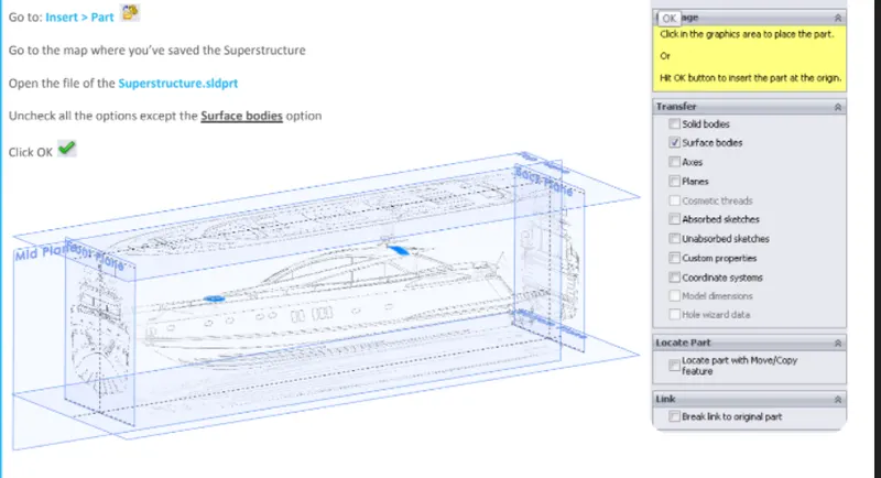
insert part
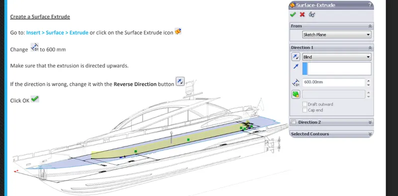
SURFACE EXTRUDE
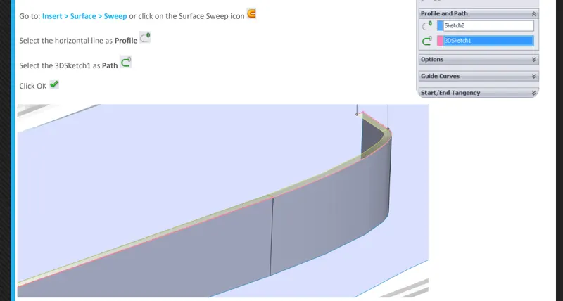
SURFACE SWEEP
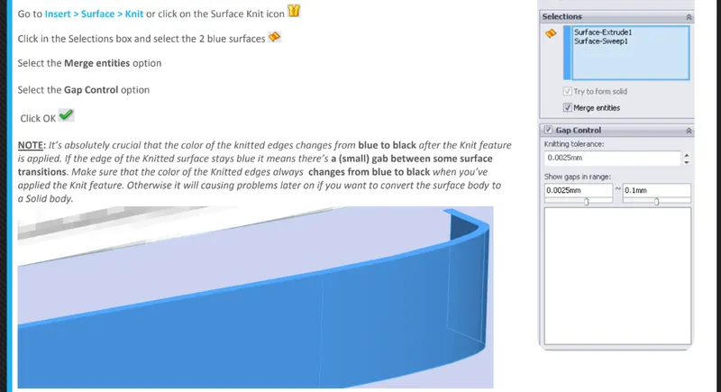
SURFACE KNIT
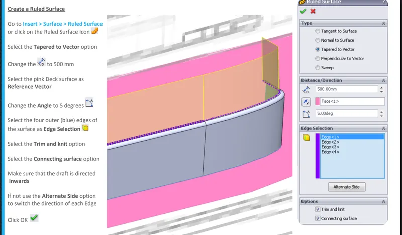
RULED SURFACE
TRIM SURFACE
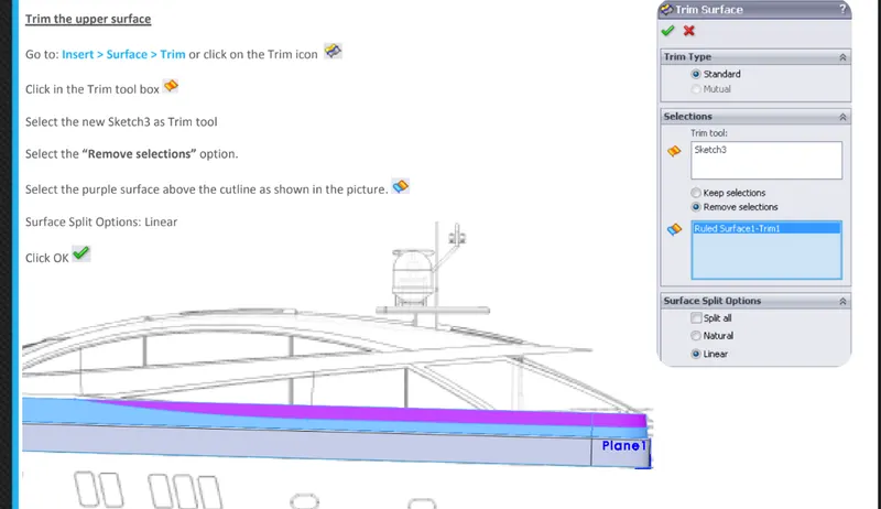
PROJECTED CURVE
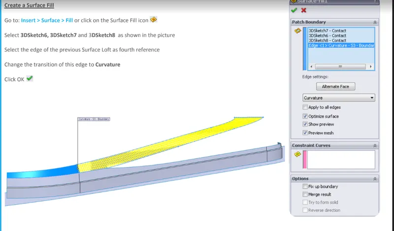
SURFACE FILL
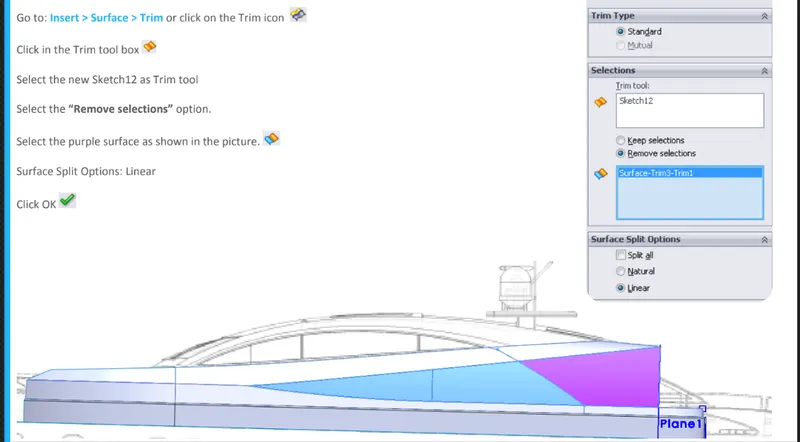
TRIM SURFACE
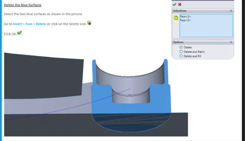
DELETE SURFACE
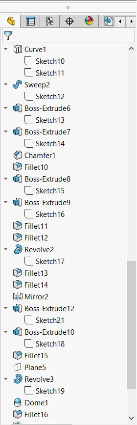
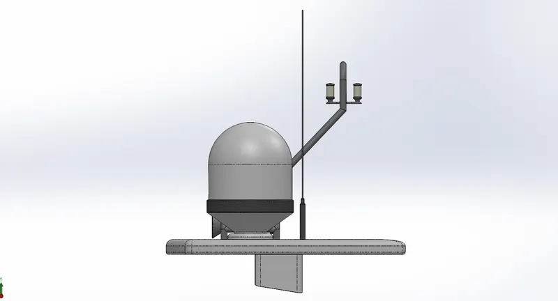
RADARMAST
INSERT PART
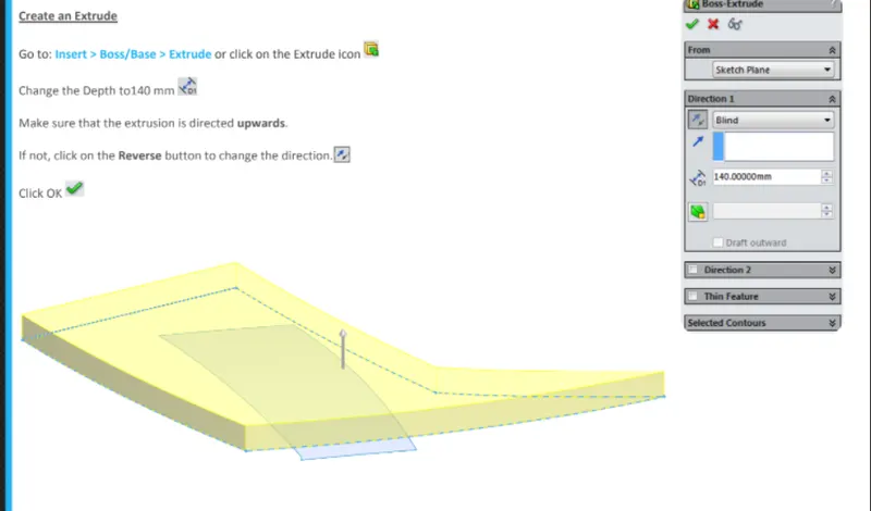
BOSS EXTRUDE
SWEEP
PROJECTED CURVE
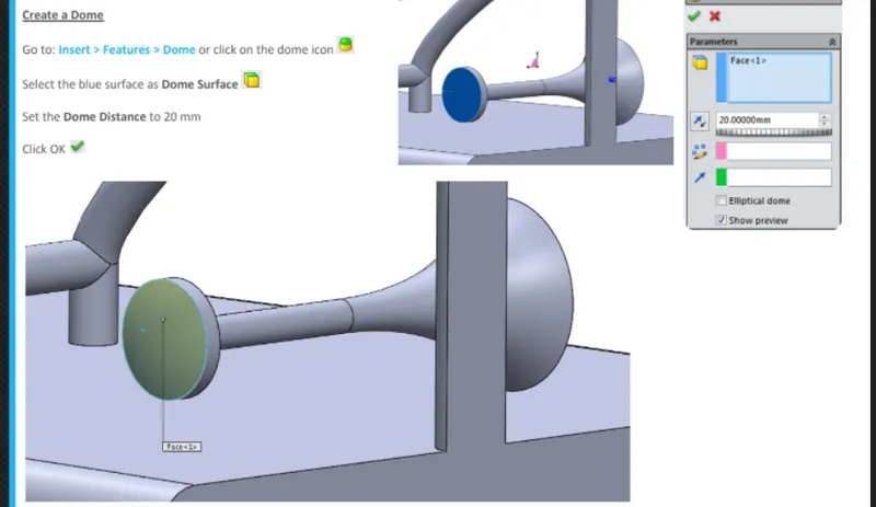
DOME
MIRROR