Photo Realistic Rendering
MODELING AND RENDERING OF AMERICAN CHOPPER
OBJECTIVE:
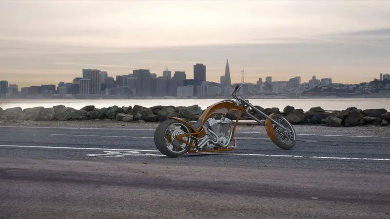
To create modeling and rendering of american chopper by using solidworks
INTRODUCTION:
In this project an American chopper is designed using SolidWorks. The chopper consists of different components such as:
• TRANSMISSION BELT AND CHAIN
• CHASSIS
• ENGINE
• PEDAL
• KICKSTAND
• FUEL TANK
• OIL TANK
• FRONT FORK
• FRONT WHEEL
• FRONT FENDER
• REAR WHEEL
• REAR FENDER
These components designed separately in different part files by making use of different features of SolidWorks
WEEK1
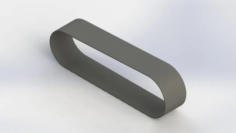
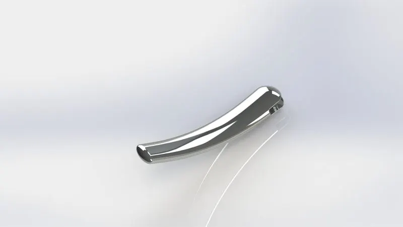
PARTS 1.Transmission belt 2. Kick stand 3. Front fender
Command's used
*2d sketch
*line and circle
*offset
*sweep
*dome
*revolve
*fillet
*split
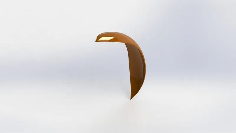
in the front fender part the axis of revolution is used based on plain
WEEK2
PARTS 1.Rear fender, 2.Chain,3.Oil tank
Command's used
*spline
*extrude
*revovle
* curve driven pattern
*combine
*shell
*extrude cut
*dynamic mirror
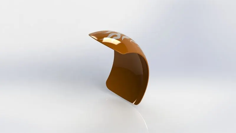
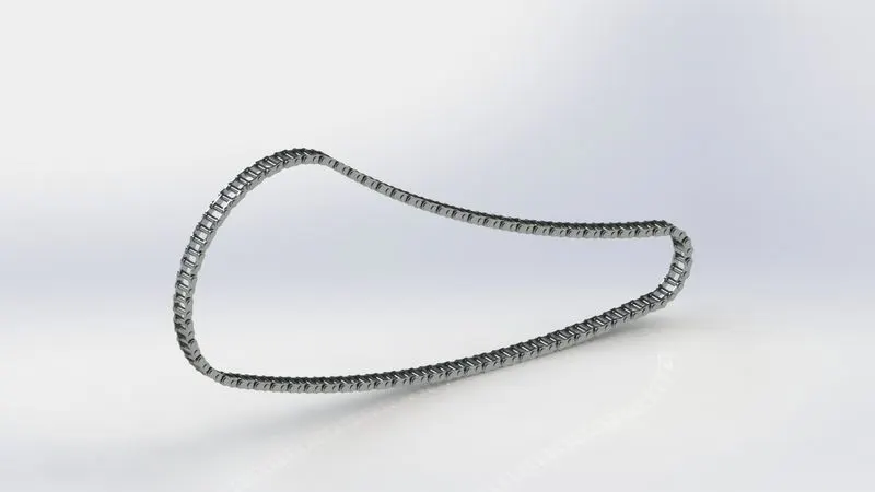
by drawing chain links and coverting them into sketch block avoids drwaing chain links again and again by reduces time, this part is very usefull
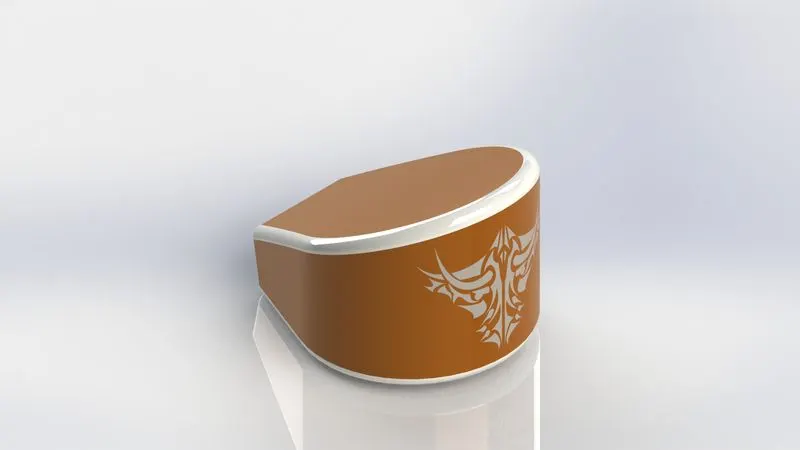
we sketch here two different geometry and used combine feature to get it into desire shape
WEEK3
PARTS 1.Pedal,2.Front wheel
Command's used
*2d sketch
*spline
* linear pattern
* revovle
*mirror
* chamfer
*revolve cut
*revolve
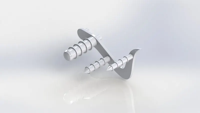
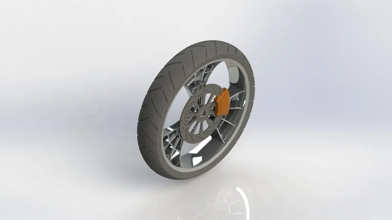
the chamfer tool is used in the brake calliper, circular and liner pattern use to create holes in the disc
the above commands, diamensions and instruction are given domeby week 3 video
WEEK4
ARTS 1. rear wheel 2.front fork
Command's used
*2d curve
*sweep
*projected curve
*dome
*revolve
*circular pattern
*spline
*mirror
*combine
*reference plane
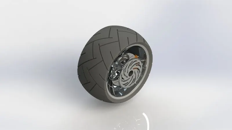
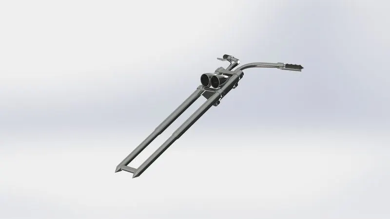
the use of projected curve and sweep gives the most accurate geometry. mirror pattern is ued to create another side of the fork and use combine feature to make it single geometry
WEEK5
PARTS: Chassis
Command's used
*2d sketch
*sketch picture
*spline
*projected curve
*extrude
*dome
*split
*mirror
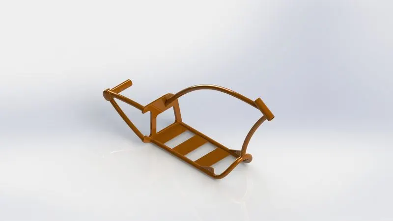
sketch picture tool is ued here to bring the image of chopper and position it as per requirement and draw the sketch according to the image
WEEK6
PART: Engine
Command's used
*2d sketch
* extrude
*mirror
*fillet
*projected curve
*combine
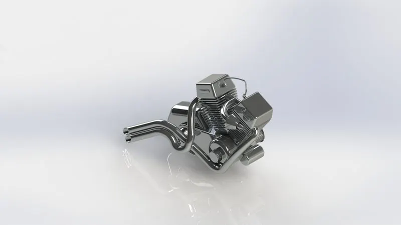
the exhaust of the engine is create by projected curve
WEEK7
PARTS: Gas tank
Command's used
*surface loft
*surface sweep
*projected curve
*knit surface
*boundery surface
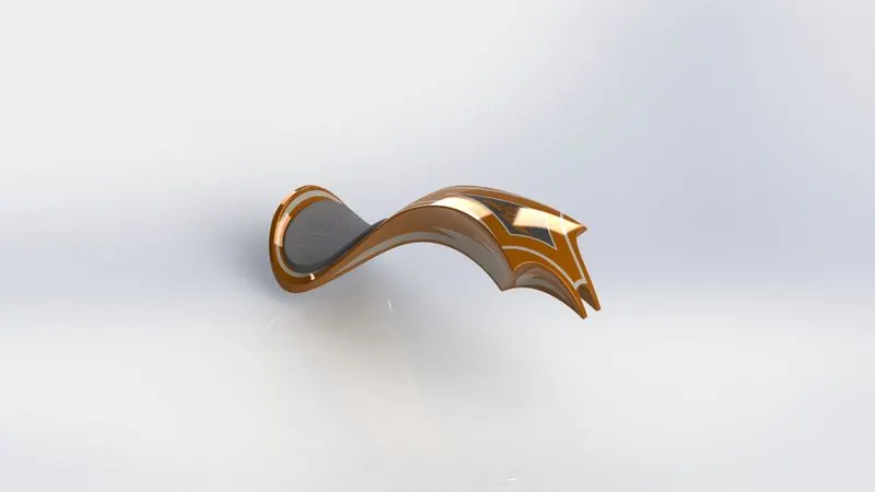
in gas tank both surface and solid extrude used
WEEK8
After makeing all parts proper appearence are given to each part to make part looks realistic
ASSEMBLY OF AMERICAN CHOPPER
to asseble the each part mates are applied, the chessis make fixed to the planes and mates are given
*concentric mate
*paralle mate
*angle mate
*width mate
*distence mate
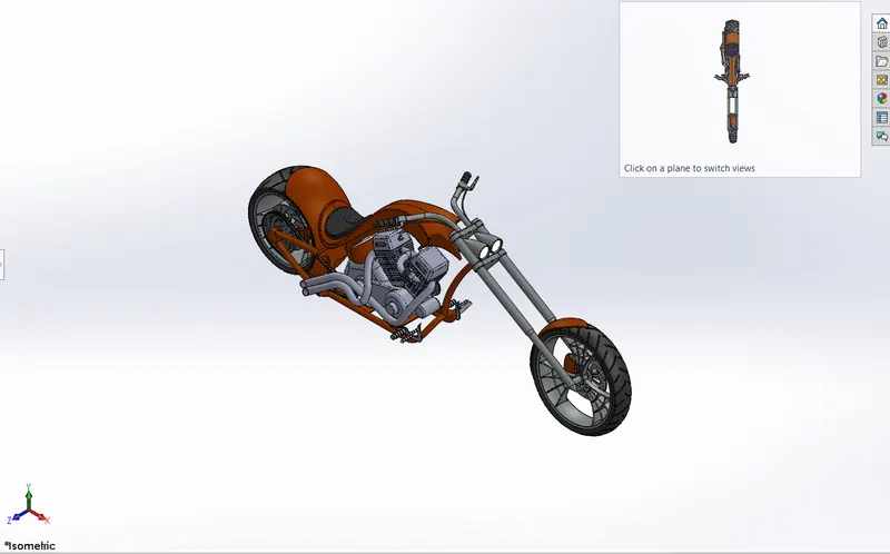
Photoview 360 rendering
to make the chopper more reailistic photoview 360 render tool is uesd with the help of some commands such as edit scenes,camera,decals
and enviorment
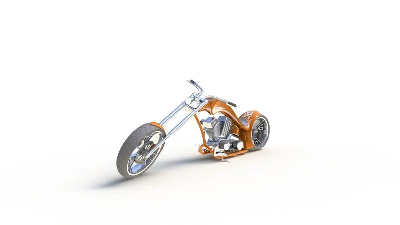
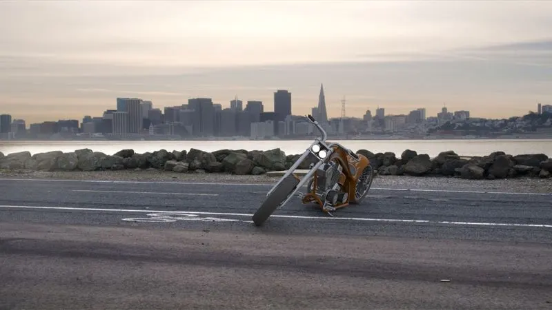
note: there was an issue with my solidworks visualization 2018 so i have created the final render in photoview360
conclusion
modeling, assembly and rendering of an american chopper is done sucessfully in solidworks