Radar Mast & Final Assembly of Yacht
SECTION-1
1. Radar Mast
Front view
Side view
Isometric view
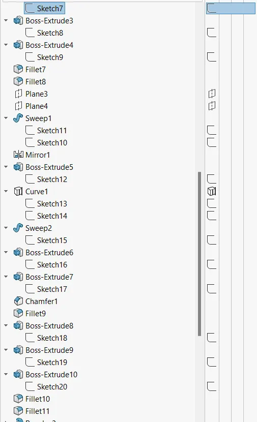
Feature manager tree
2. Yacht Assembly
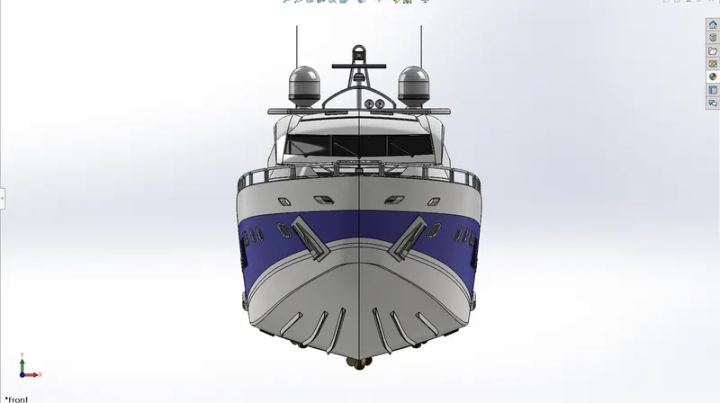
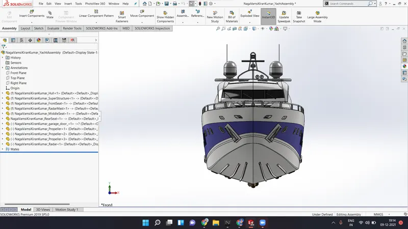
Front view
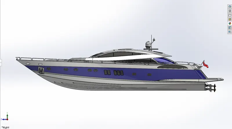
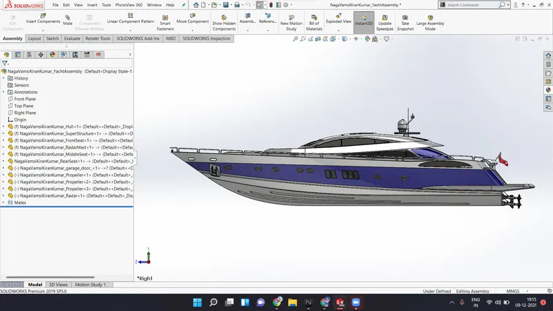
Side view
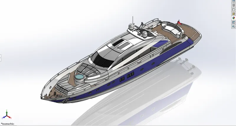
Isometric view
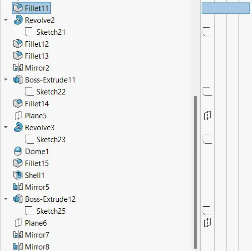
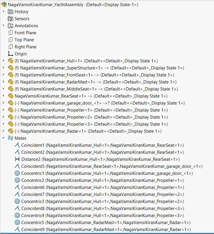
Feature manager tree
SECTION-2
PROJECT REPORT - SUNSEEKER PREDATOR YACHT
Objective :
The main objective of the project is to design the individual components of the Sunseeker Predator Yacht using the SolidWorks software and to assemble them. After completing the assembly of the Yacht, to render it with SolidWorks PhotoView 360 (Render tool) to create a photorealistic view of the Yacht.
Introduction :
SolidWorks :-
SolidWorks is a 3D CAD design software, analysis software and product data management software which is developed by the Dassault systems. At the initial stage, the software is used for planning, feasibility assessment, prototyping and project management. The software is then used for design and building of mechanical, electrical and software elements.
Sunseeker Predator Yacht :-
Sunseeker international is a British luxury performance motor yacht brand. A yacht is a sail or power vessel used for pleasure, cruising or racing. The yacht consists of a cabin with amenities that accommodate overnight use. Originally all yachts were made of wood, using a wooden keel and ribs, clad with planks. These materials were supplanted with iron or steel in steam yachts. A predator is a super yacht built in 2008 at the Dutch shipyard Royal De Vries Aalsmeer.
Design methodology :
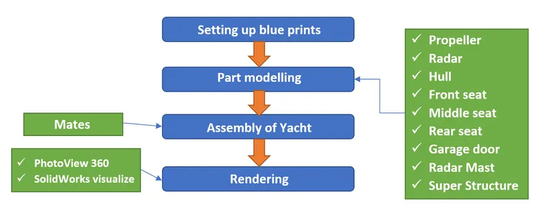
The main steps involved in the design methodology are.
Description of tools, features and part files :
sketch tools :-
- Line
- Circle
- Arc
- Spline
- Rectangle
- Fillet
- Offset entities
- Convert entities
- Trim and Extend entities
- Mirror entities
- Smart dimensioning
3D modelling tools :-
- Boss extrude
- Cut extrude
- Revolve boss
- Sweep boss
- Fillet and Chamfer
- Linear pattern
- Shell
- Mirror
- Reference planes
- Projection curve and Split line
Surfacing tools :-
- Extruded surface
- Revolve surface
- Swept surface
- Lofted surface
- Surface fill
- Offset surface
- Ruled surface
- Fillet
- Delete face
- Extend surface
- Trim surface
- Knit surface
Description of modelled parts :
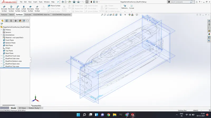
1. Blueprint setup - The reference blueprint images having views of front, side, top, bottom and rearview. All views are imported into the SolidWorks workspace, and they are arranged with respective planes. Apart from front plane, right plane and top plane, back and bottom planes are created.
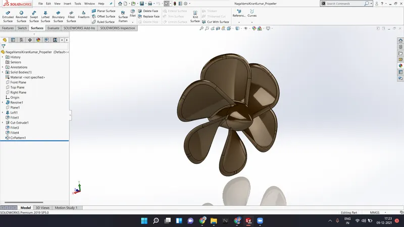
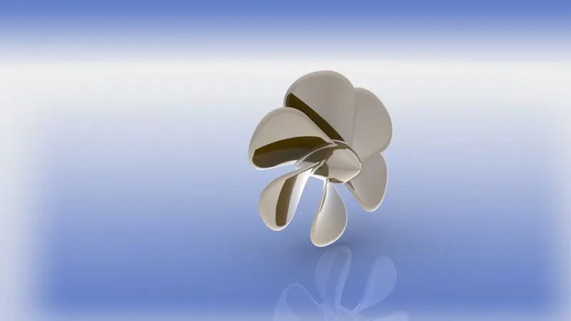
2. Propeller - A propeller consisting of a set of spiral shaped blades around the circular hub. The propeller is made to rotate at the rear end of the sailing boat, which converts the power into linear thrust. The propeller is modelled using the simple solid modelling tools such as boss extrude, cut extrude, projection curve and loft. First a single blade is lofted, and then it is circularly patterned. To smoothen the sharp edges, fillet is applied.
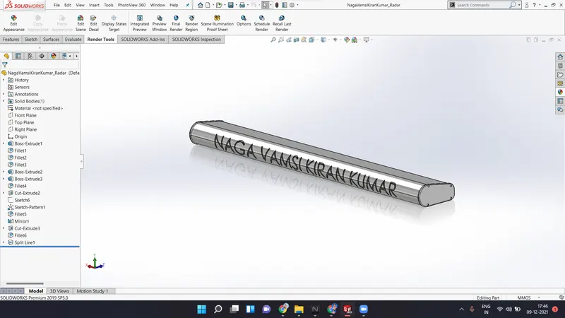
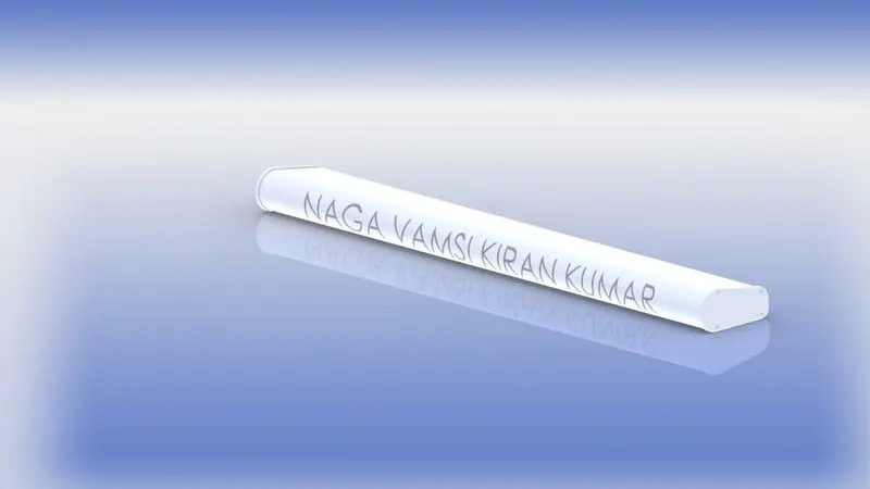
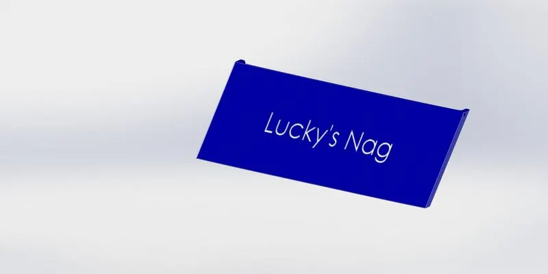
3. Radar - Radio detection and ranging, simply radar, is a detection system that uses radio waves to determine the distance (range), angle or velocity of objects around it. The objects such as aircraft, ships, guided missiles, weather information, terrain, etc. The radar is modelled using the simple solid modelling tools such as extruded boss, cut extrude, fillet and text tools are used to indent the text on it.
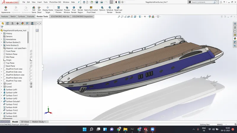
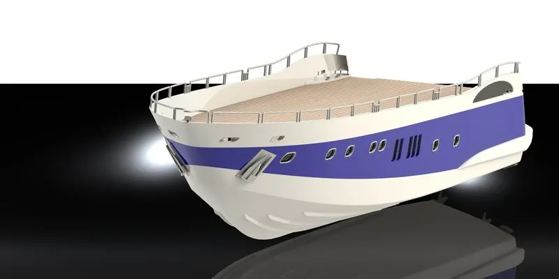
4. Hull - A hull is the watertight body of a ship or boat. The hull may open at the top, or it may be fully or partially covered by the deck may be deck house and other superstructures. The line where the hull meets the water surface is called the waterline. The hull is completely designed using the surfacing tools. The curves for creating the surfaces are generated using the projected curves, where two sketches are projected as a single curve. The surfacing tools used for designing the hull are surface extrude, lofted surface, boundary surface, surface fill, trim surface, extend surface, split line and ruled surface. All the individual surfaces are merged together using the knit tool and a solid is created. The solid modelling tools used are boss extrude, cut extrude, fillet and mirror.
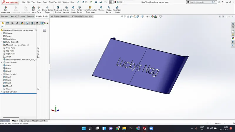
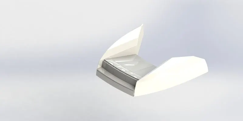
5. Garage door - In previous model, a space is created under the hull floor surface for garage. The space is simply cut extruded from the feature using the split tool and that extruded portion is saved separately. Now that saved port is opened, and the door is created from that reference part. The tools used are cut extrude, fillet, etc.
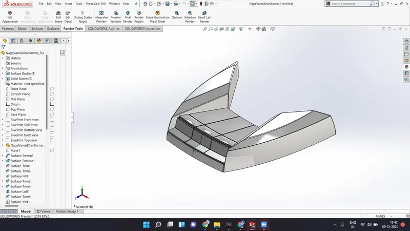
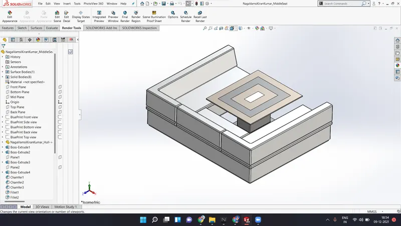
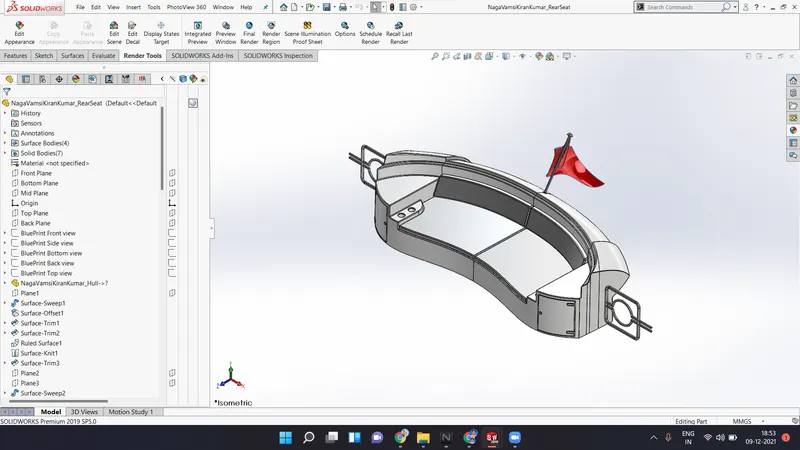
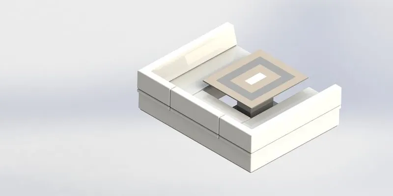
6. Modelling of seats - Seats are modelled using surface and solid modelling tools. The yacht consist of three seating, front, middle and rear. The seats are modelled using surfacing tools like extrude surface, sweep surface, trim surface, knit surface, etc.
Front seat
Middle seat
Rear seat
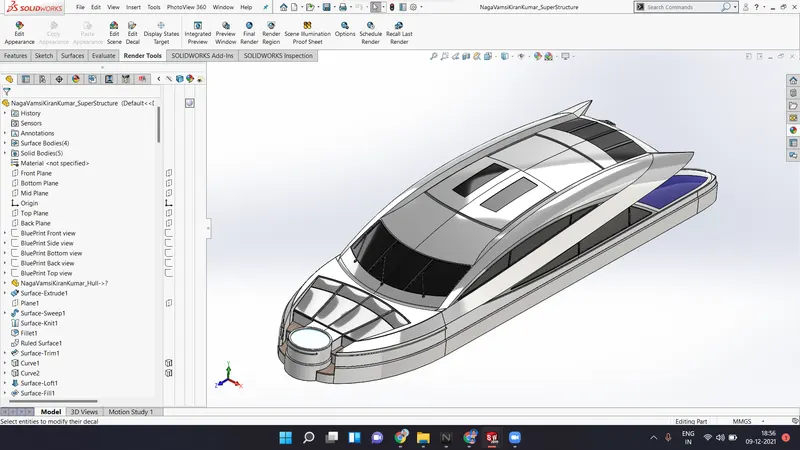
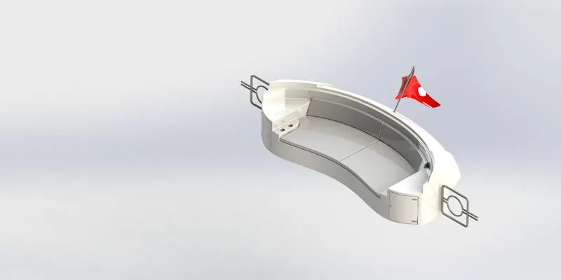
7. Super structure - This is the hardest part to model in yacht. The super structure is nothing but a cabin which include all facilities for passengers. This part is firstly completely modelled using the surfacing tools, and then all surfaced are knit and merged together to create a solid. In this model, the railings are modelled by using the solid modelling features. The various types of solid modelling and surfacing tools are used to create this model. All the sharp edges are filleted to create a smooth look when rendered. Full body of the super structure are created using the surfacing features and other parts likes railings and wipers are created using the solid modelling features. A nice view is created by applying various appearances, as shown in the below image.
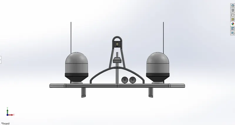
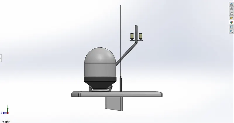
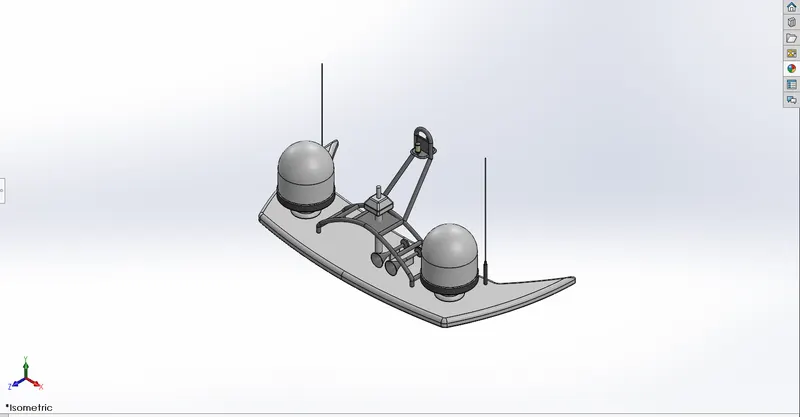
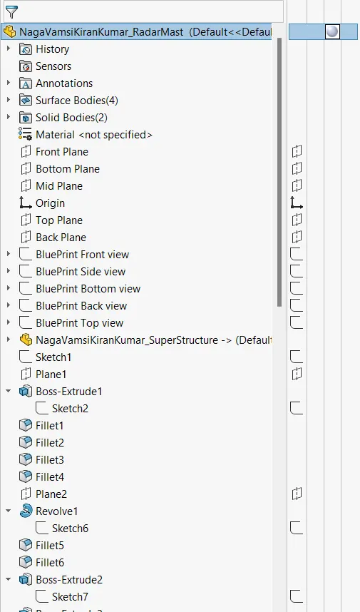
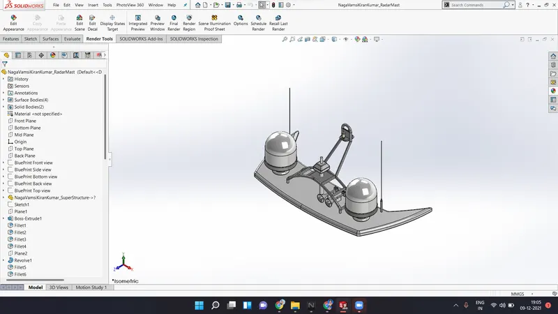
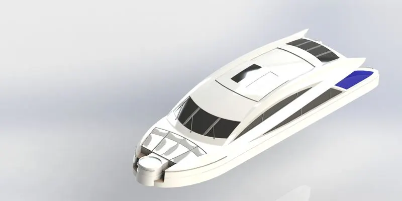
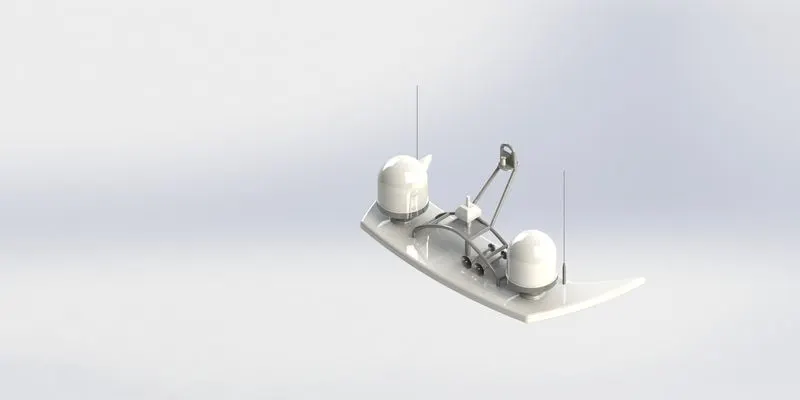
8. Radar mast - The mast of a boat is a tall spar, or arrangement of spars, erected more or less vertically on the centerline of a ship or boat. It purpose of the radar must is carrying sails, spars and derricks and giving necessary height to a navigation light, look out position, signal yard, control position, radio aerial or signal lamp. Here the mast consists of two light bulbs and two antennas. The radar mast is created using the solid modelling features like extrude boss, cut extrude, fillet and swept boss. Revolve and shell features are used to create the horns. Fillets are used to smoothen the sharp edges. The mirror feature is used to mirror the solid bodies.
Assembly :
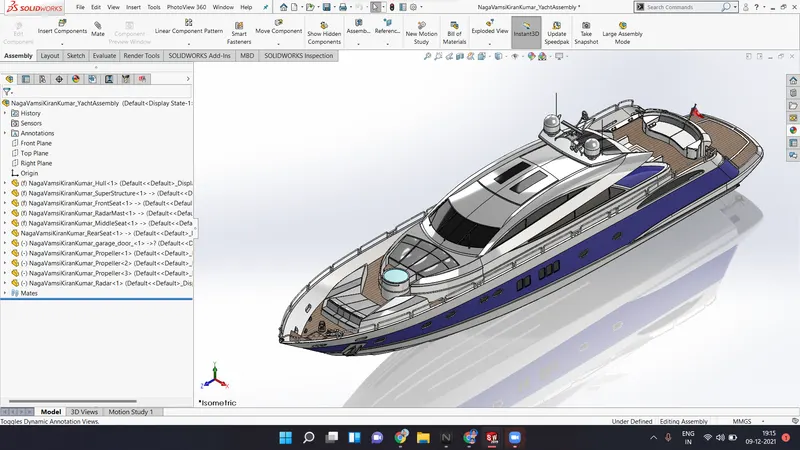
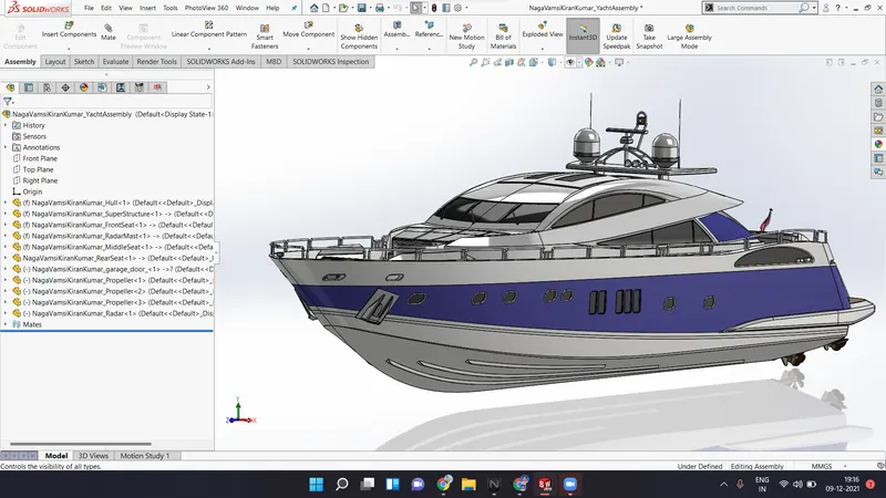
There are two types of approaches in assembly of a model. Top down and bottom up approach. In modelling of the sunseeker predator yacht, bottom up approach is implemented. The individual parts are first designed, and then they are assembled together.
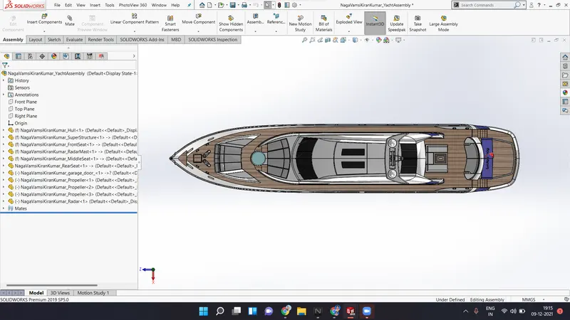
For assembling the yacht, all individual models are imported into the assembly workspace, and they are placed relative to the other parts. Mates are used to create the geometric relationship between the individual parts. The various types of mates used are concentric, coincident, distance, etc.
Assembly views of the Yacht :
Front view
Side view
Top view
Isometric view
Custom view
Rendering :
The photo realistic renders are created in SolidWorks using the add-in called PhotoView 360. The rendering of the image include setting up the environment, arranging the lights, setting up the scenes and creating the final view of the designed part. SolidWorks visualize is also an add-in which is used to create the high quality rendered images with minimum amount of time.
The rendered images of the Yacht parts are :
Propeller
Radar
Hull
Garage door
Front seat
Middle seat
Rear seat
Super structure
Radar mast
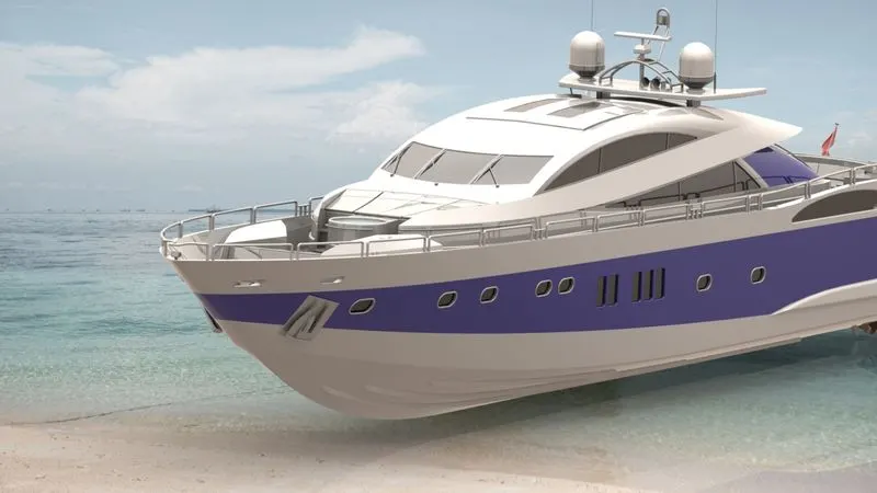
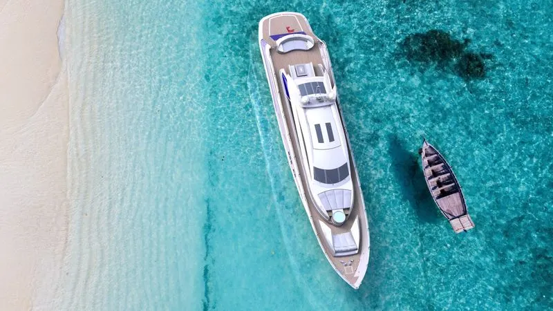
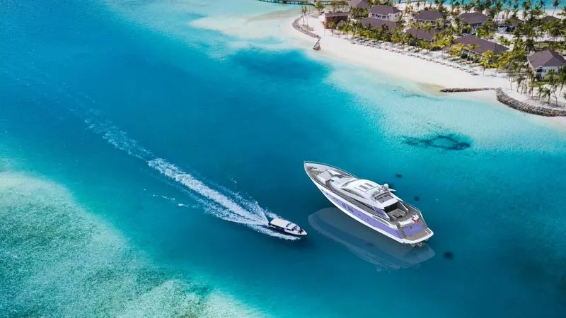
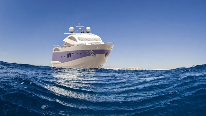
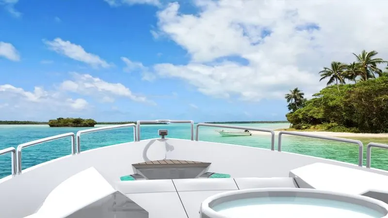
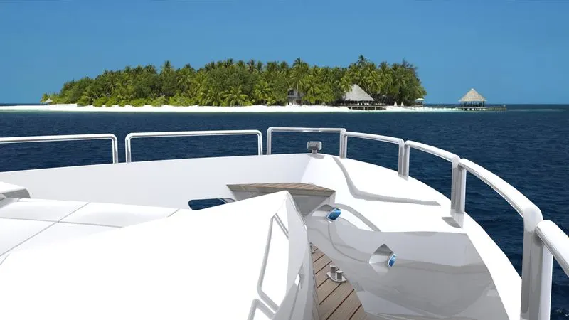
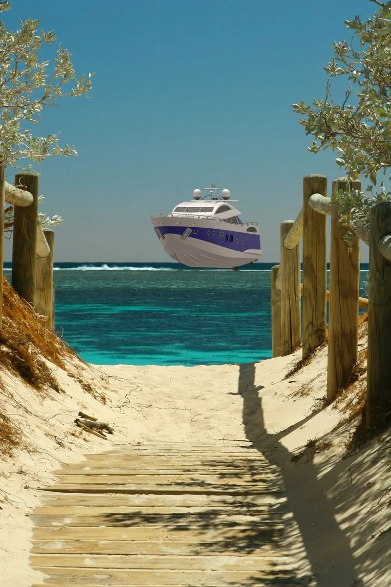
Rendered images of Sunseeker Predator Yacht :
Conclusion :
The individual parts of the Sunseeker Predator Yacht are designed and are assembled together to create the model of the Yacht using SolidWorks. In this project, I have learned the purpose and arrangement of blueprints in the workspace, and use of power surfacing tools to create the complex designs and shapes. This project has been given me insight into marine vehicle design.
Link to files - https://drive.google.com/drive/folders/1VzREj9IAnuYsUVryijM1cKOURAFrt1Ja?usp=sharing