Radar Mast & Final Assembly of Yacht
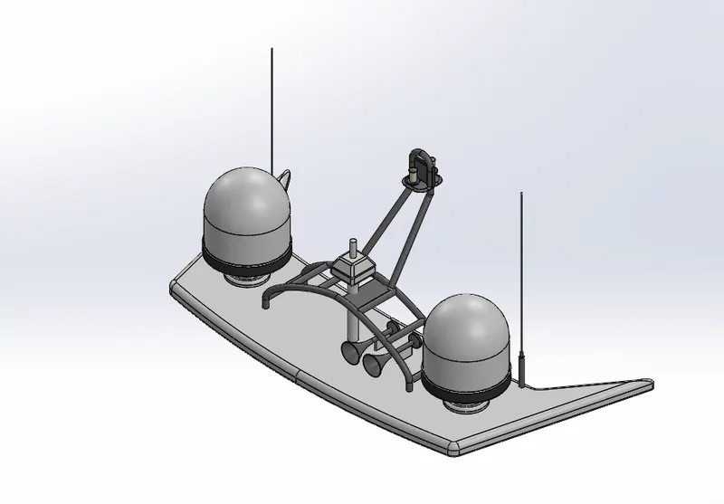
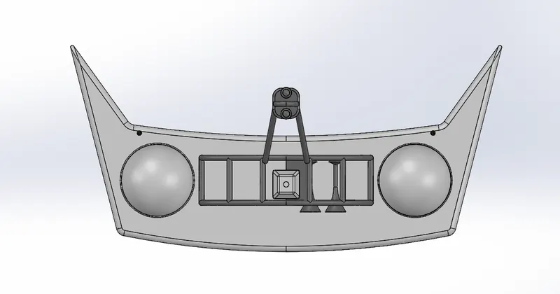
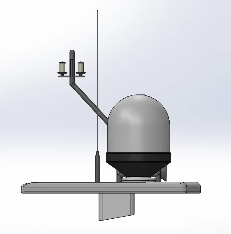
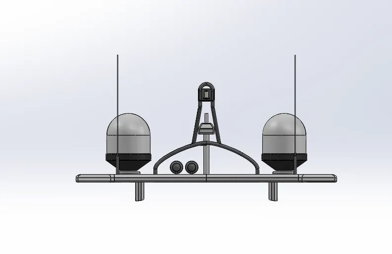
RADAR MAST
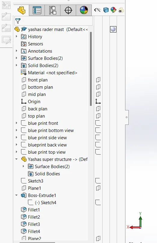
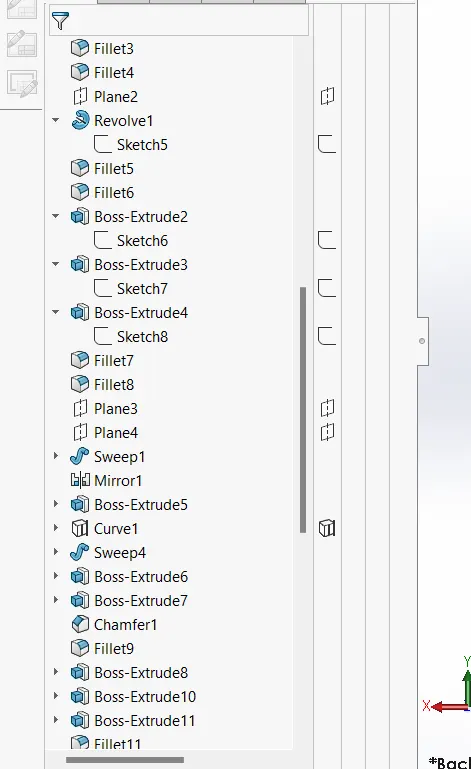
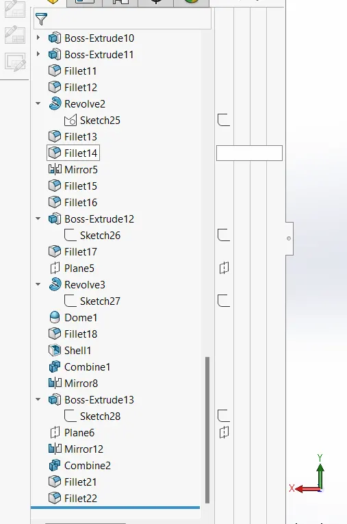
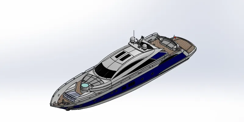
YATCH ASSEMBLY
--------------------------------------------------------------------------------------------------------------------------------------------------------------------------------------------------------------------------------------------------------------------------------------
INTRODUCTION
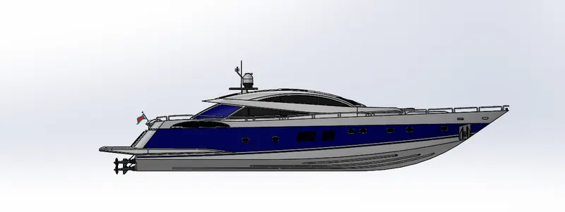
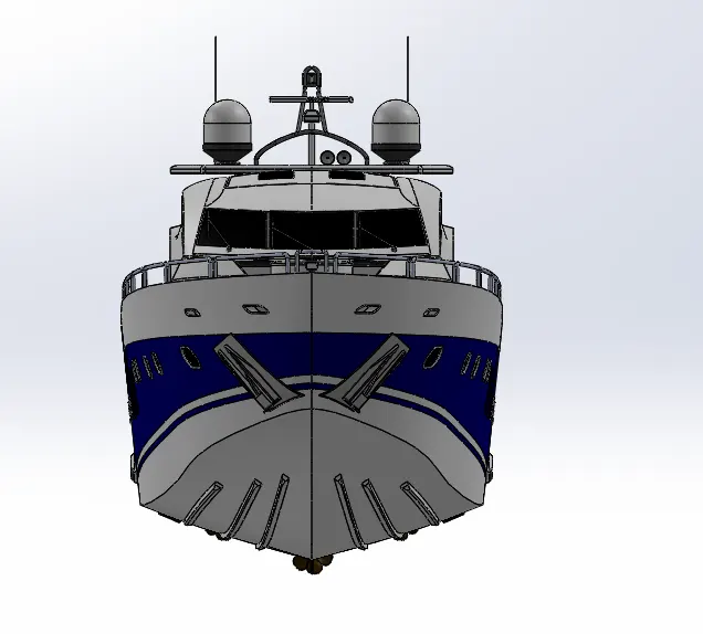
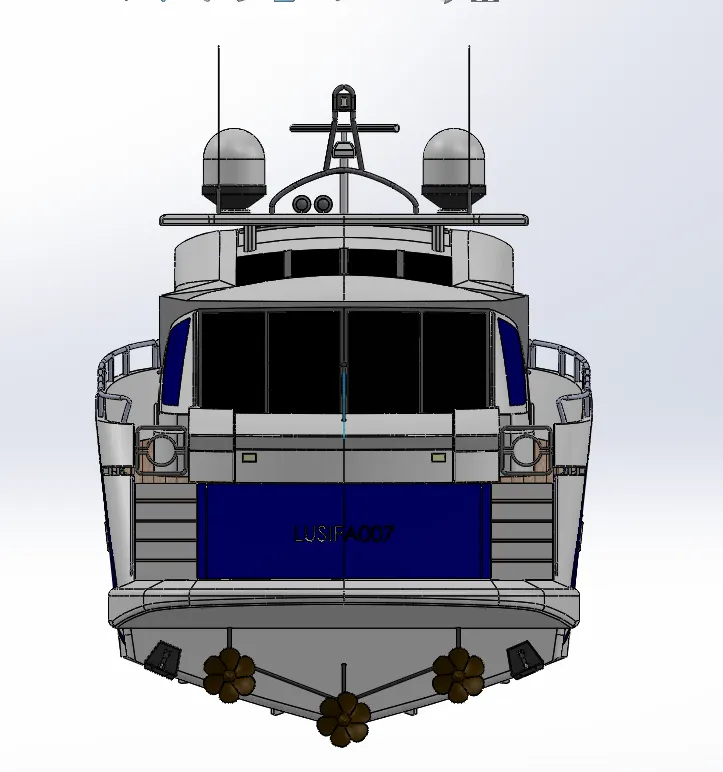
In this we will lear about desgin of HULL and assembly whit the help of solid works and SOLIDWORK visualliz . We learn about sketching and converting the sketch into 3d modal AND SURFACE MODALING
key point:-
[In this we lern more about surface modelling]
.After compliting design of every part . we do the assembly In order to make THE HULL .after assembly.To give realeastic look we add decal,light,camera and do some rendaring of YATCH using SOLIDWORK visualization.
THE COMPONENTS WHICH WE DESGINE ARE :-
.BLUEPRINT SETUP
. FRONT SEAT OF HULL
.MIDAL SEAT OF HULL
.RARE SEAT OFHULL
.PROPELLER
.RADAR MAST
.RADAR
.THE HULL MAIN BODY
.THE SUPERSTRUCTURE
.FINAL ASSEMBLY
.RENDARING OF HULL
OBJECTIVE:-
. To creat parts using SOLIDWORK
. Doing assambly using SOLIDWORK
. Rendering using SOLIDWORK visulalization
In this entire assembly of chopper .The commenly used commends are:-
= Extrude boss.
= Fillet ,chamfer.
=swept boss base.
=swept surface.
= Extrude cut .
= Shell.
= mirror .
=filled surface.
=extrude surface.
=delete face.
=ruled surface.
=offset surface.
=lofted surface.
= Reference geomatry.
= Projected curve .
= Knit.
=dome.
-------------------------------------------------------------------------------------------------------------------------------------------------------------------------------------------------------------------------
Detaild explination about all the features used.
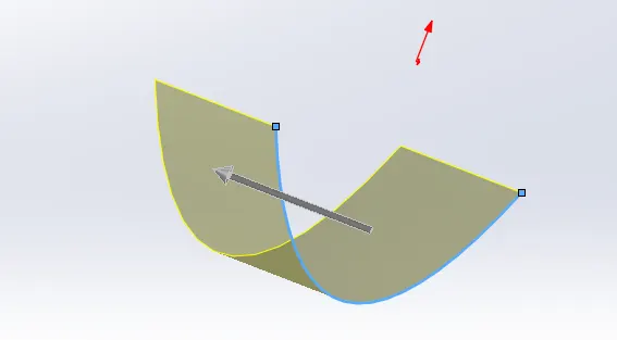
=surface extrude.
Surface extrude and Boss base extrude Are different features but does the the same principle. When we need to to extrude the sketch to form of 3D surface . But in surface extrude we dont need closed sketch.
=Fillate,Chamfer.
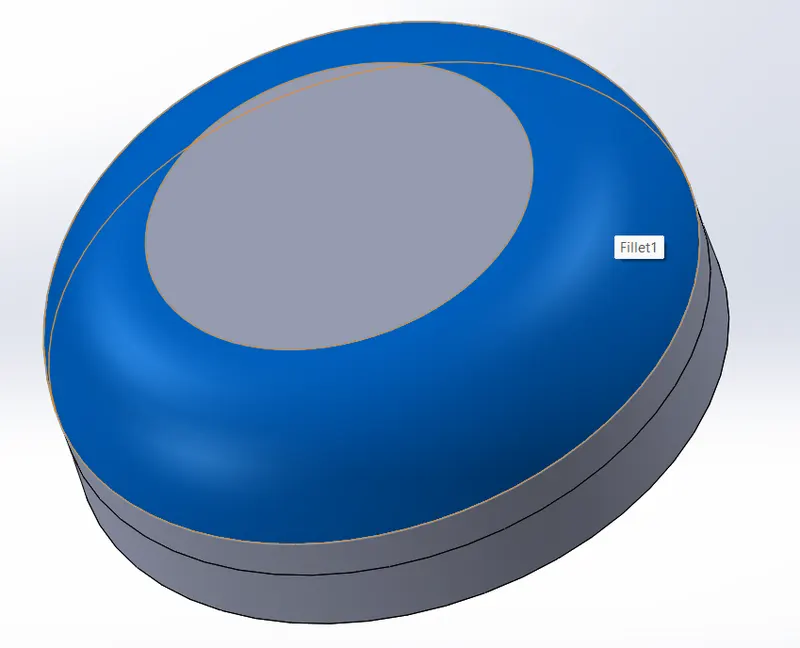
Fillet are most commonly used feature it is used to create a smooth surface in the edges of the solid body . To get a circular finish.
=Shell
Shell is a handy tool. Which is used to create a hollow solid body. In this we can give the the outer thickness of the solid body. Which only keeps the the thickness of the the exterior of the body and makes the the body hollow by inside. Which are mainly used to create tank etc.
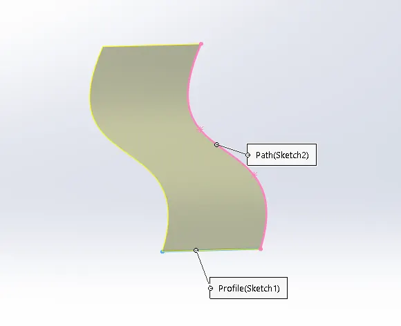
=SWEPT SURFACSE
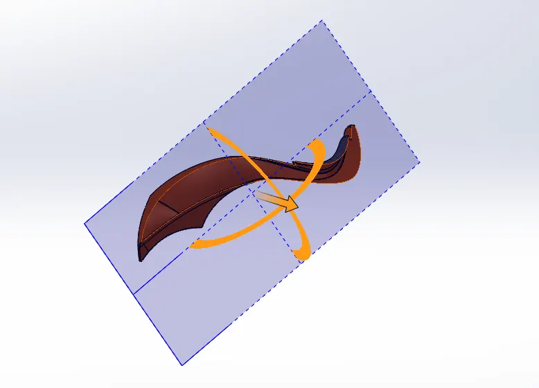
Swept surface and swept Boss base are the different features which follows the same principle. In swept surface we can select the sketch and the guided curve .so that surface will be formed as per the curve . Swept Boss base we should have a closed sketch in order to to do a a swept Boss base.
=EXTRUDE CUT
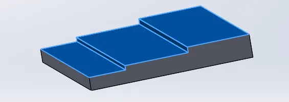
Extrude cut is a feature which is used in a solid body . To to remove unwanted part. As per the required design.
=Mirror
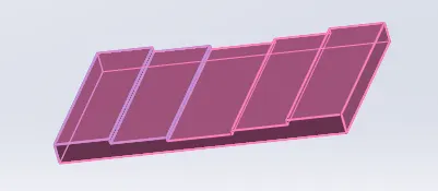
Mirror is a feature which saves time . When we have to design a part which is symmetrical. We can only do the half of the part and mirror the remaining half so that it saves time . We can select the plane to mirror for face to measure. And select the bodies to mirror option. And we can get a full completed designed body.
=filled surface.
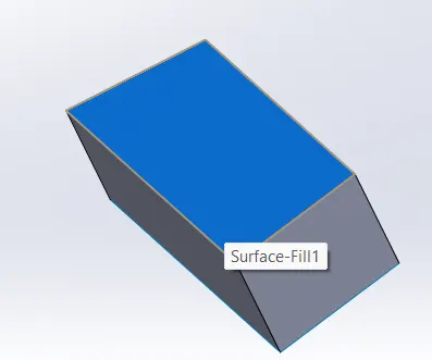
This is a feature which is used to to close a open surface . We can select the edges of the open surface in a order . We will get a a filled surface.
= lofted surface.
Lofted surface is a feature which is same as filled surface. In filled surface we can't get a precised surface . So in lofted surface by using guiding curves we can get a well finished surface.
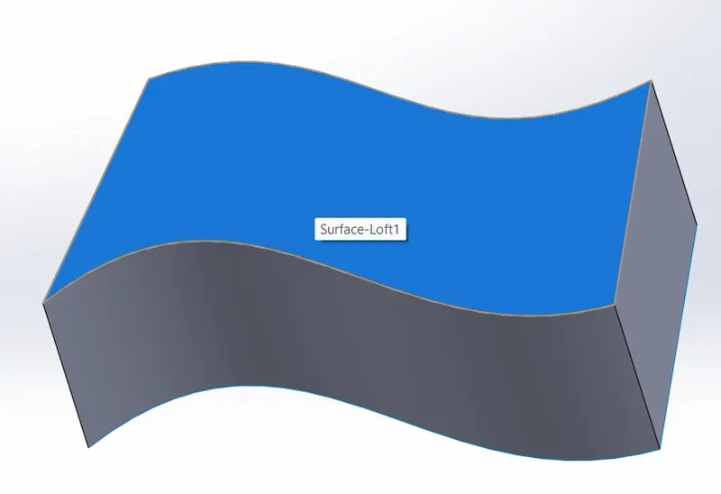
=Delete face
This is the feature used to delete unwanted face or surface. In this we have different options we can even delete the face and feel the surface .
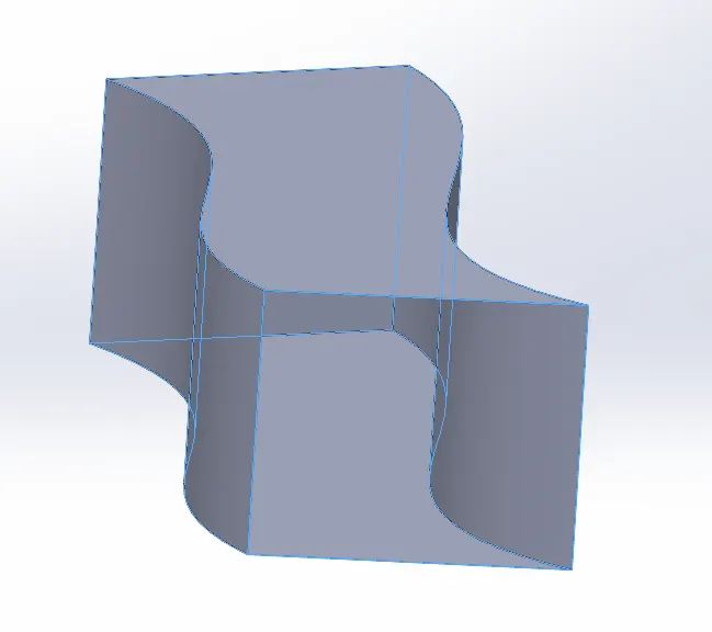
=ruled surface.
Ruled surface helps to create a extrude of surface . From its previous shape with given angle and length.
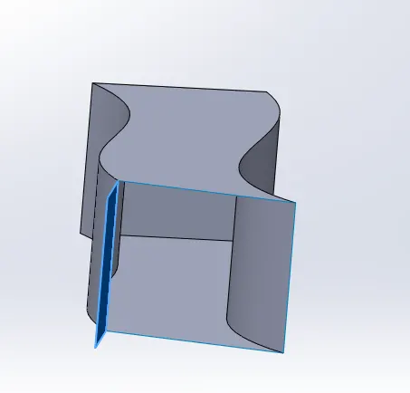
=offset surface.
It is used to create a offset [replica of surface] above or below the surface which is selected . With the given dimension gap .
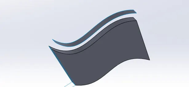
= Knit.
It is mainly used to to combine different parts or surfaces which are created to form a one single body. Its most commonly used in the final stage of the the modelling to form a solid body or a combined body.
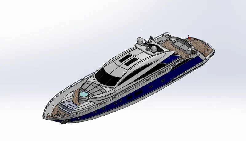
==================================================================================================================================
All the parts used to create Hull and features used in the parts
. FRONT SEAT OF HULL
.MIDAL SEAT OF HULL
.RARE SEAT OFHULL
.PROPELLER
.RADAR MAST
.RADAR
.THE HULL MAIN BODY
.THE SUPERSTRUCTURE
.FINAL ASSEMBLY
.RENDARING OF HULL
FEATURE USED:-
= Extrude boss.
= Fillet ,chamfer.
=swept boss base.
=swept surface.
= Extrude cut .
= mirror .
=filled surface.
=extrude surface.
=ruled surface.
=offset surface.
=lofted surface.
= Reference geomatry.
= Knit.
=dome.
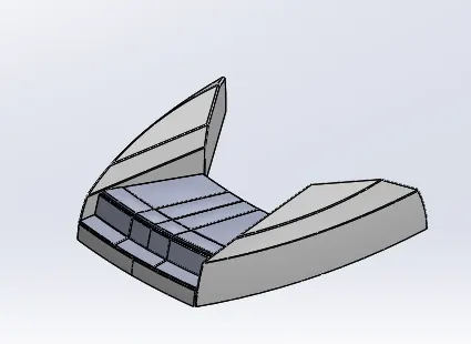
MIDAL SEAT OF HULL.
FETURE USED:-
= Extrude boss.
= Fillet ,chamfer.
=swept boss base.
=swept surface.
= Extrude cut .
= mirror .
=filled surface.
=extrude surface.
=ruled surface.
=offset surface.
=lofted surface.
= Reference geomatry.
= Knit.
=dome.
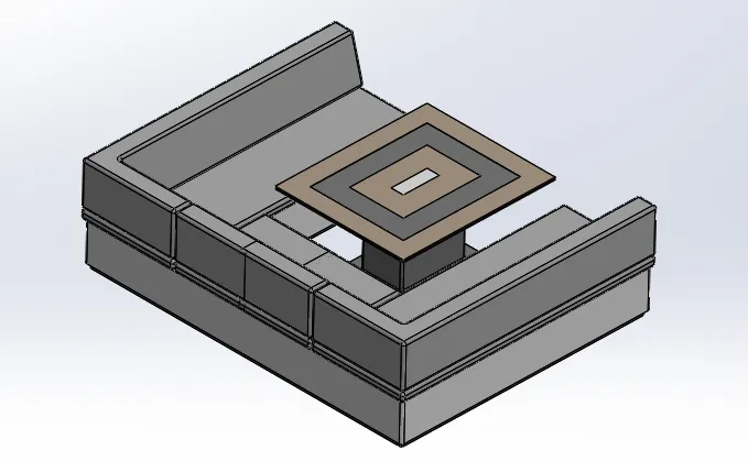
RARE SEAT OFHULL.
FETURE USED:-
= Extrude boss.
= Fillet ,chamfer.
=swept boss base.
=swept surface.
= Extrude cut .
= mirror .
=filled surface.
=extrude surface.
=ruled surface.
=offset surface.
=lofted surface.
= Reference geomatry.
= Knit.
=dome.
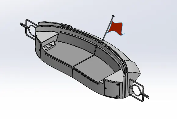
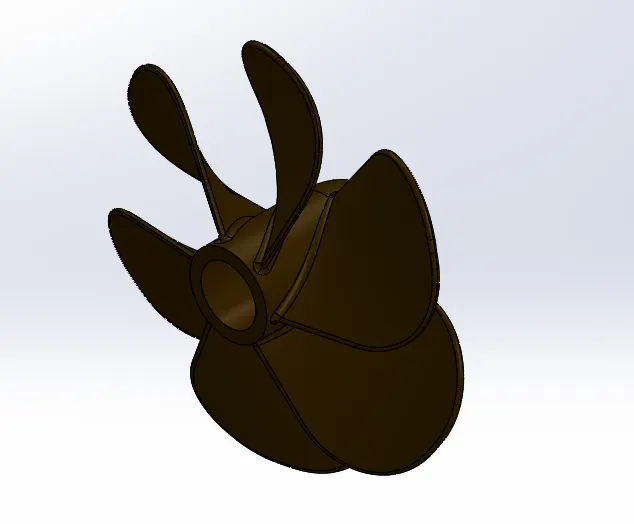
.PROPELLER
FETURE USED:-
=REVOLVE.
=CUTEXTRUD.
=FILLET.
=LOFT.
= CIRPATTREN.
.RADAR MAST
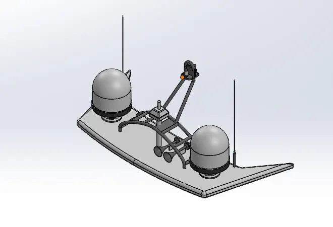
FETURE USED:-
=REVOLVE.
=CUTEXTRUD.
=FILLET.
=LOFT.
=SHELL.
=BOSS EXTRUDE.
=MIRROR
=DOME.
.RADAR
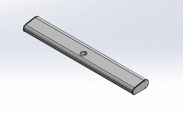
FETURE USED:-
=BOSS EXTRUDE.
=FILLAT.
=CUTEXTRUDE.
=SPLIT LINE.
=MIRROR.
.THE HULL MAIN BODY
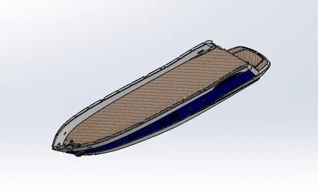
FETURE USED:-
= Extrude boss.
= Fillet ,chamfer.
=swept boss base.
=swept surface.
= Extrude cut .
= Shell.
= mirror .
=filled surface.
=extrude surface.
=delete face.
=ruled surface.
=offset surface.
=lofted surface.
= Reference geomatry.
= Projected curve .
=DICALS.
= Knit.
=dome.
.THE SUPERSTRUCTURE
FETURE USED:-
= Extrude boss.
= Fillet ,chamfer.
=swept boss base.
=swept surface.
= Extrude cut .
= Shell.
= mirror .
=filled surface.
=extrude surface.
=delete face.
=ruled surface.
=offset surface.
=lofted surface.
= Reference geomatry.
= Projected curve .
=DICALS.
= Knit.
=dome.
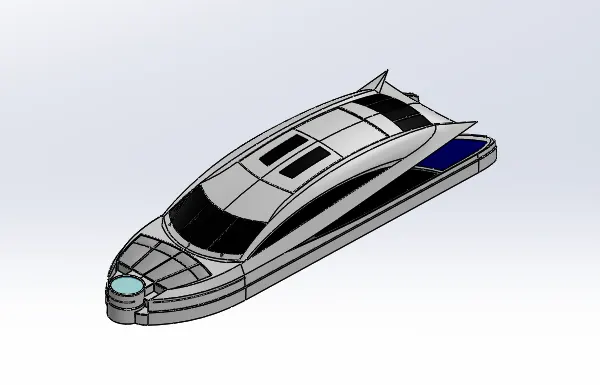
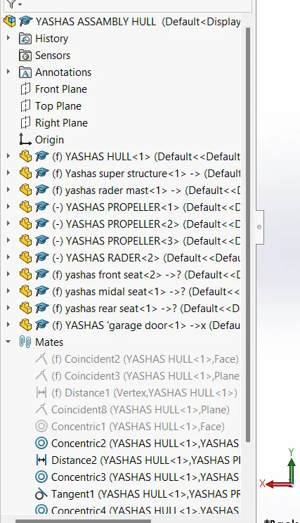
.FINAL ASSEMBLY
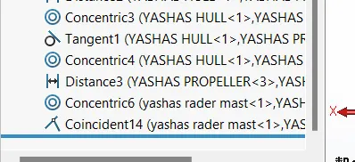
ALL THE MATES USED:-
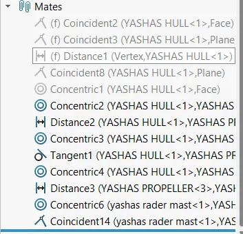
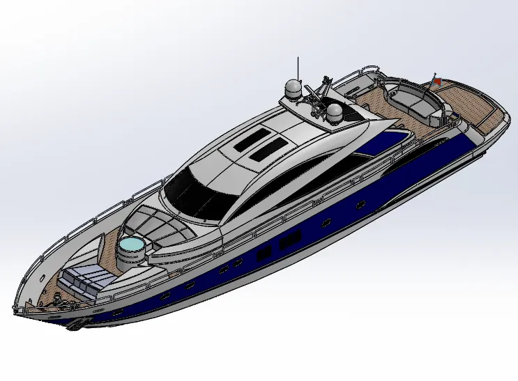
===========================================================================================================================
.RENDARING OF HULL:-
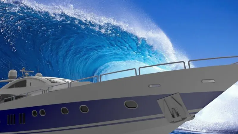
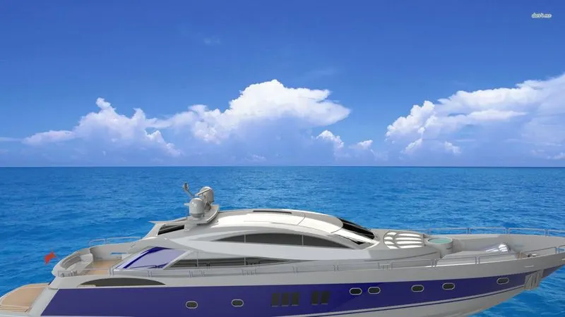
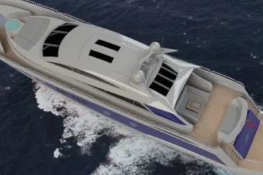
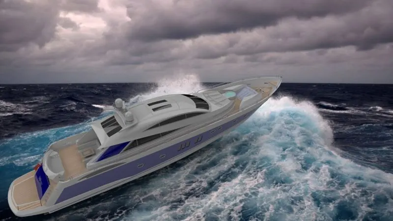
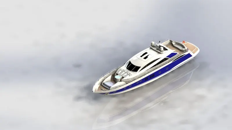
Rendering:- The term rendering comes from the graphic world where a rendering is an artistic drawing of what a new structure would look like. In Computer Aided Design (CAD), a rendering is a particular view of a realistic image.
THIS ARE THE RENDERD IMAGES OF HULL
_________________________________________________________________________________________________
____________________________________________________________________________________________________
________________________________________________________________________________________________________
________________________________________________________________________________________________________________
_________________________________________________________________________________________________
Conclusion
- In this we have completed the more assembly and rendering of the hull. The features mostly used on this model is surface modelling. And we learnt all the new things on surface modelling.
___________________________________________________________ THANK YOU_____________