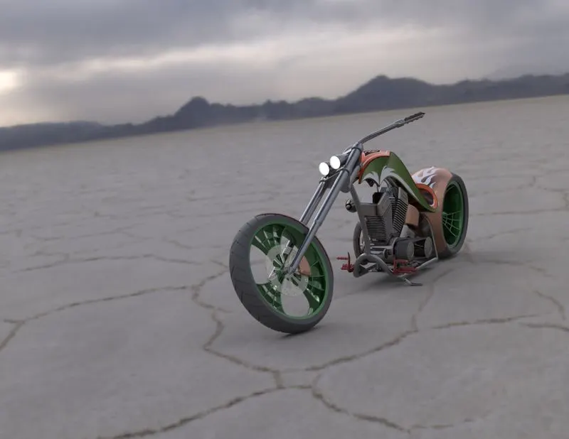
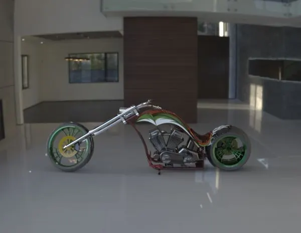
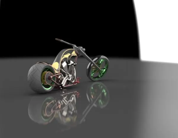
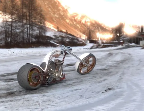
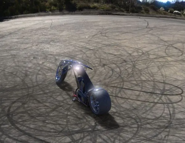
Photo Realistic Rendering
INTRODUCTION
In this we lear about desgin of american chopper and assembly whit the help of solid works and SOLIDWORK visualliz . We learnt about sketching and converting the sketch into 3d modal .After comliting design of every part . We start assembly of all the parts .In order to make a chopper .after assembly to give realeastic look we add decal,light,camera and do some rendaring of chopper using SOLIDWORK visualization.
THE COMPONENTS WHICH WE DESGINE ARE :-
1. Chassi.
2. Engin with exhoust pipe .
3. Front weel and rear wheel with rims and spoketcalipers.
4. Front fork .
5. Front and rear fender
6. Oil tank
7. Chain and transmission belt
8. Kickstand and foot pedal
OBJECTIVE:-
. To creat parts using SOLIDWORK
. Doing assambly using SOLIDWORK
. Rendering using SOLIDWORK visulalization
In this entire assembly of chopper .The commenly used commends are:-
= Extrude boss
= Fillet
= Revolve boss feature
= Extrude cut
= Shell
= Liner pattern
= mirror
= Reference geomatry
= Projected curve
= Knit
= Mate
Extrude Boss:-
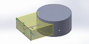
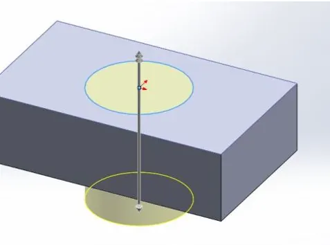
It is the most comenly used feature . To uderstand in a easy way . it helps to convert 2d desgines into a solid bodys .
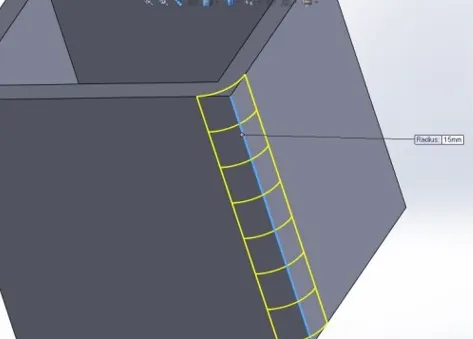
Fillet:- When we draw a solid part it is having some sharp edges. To give the roundness to those edges we add fillets.
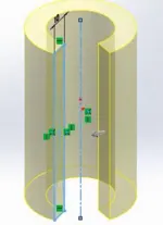
Revolve boss feature:- This feature works around an axis, by selecting axis of a sketch it adds a round material by revolving around that axis.
Extrude cut:- As the name implies, it cuts the geometry which we don’t need from the part or it can be used to give the desired shape to the sketch or solid part.
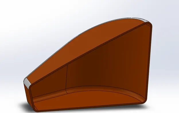
Shell:- It is very handy tool in SOLIDWORKS. It gives some sort of idea that how inside geometry of a part will appear.
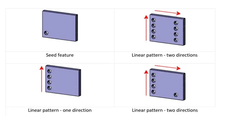
Linear pattern:- Linear pattern is used to create single sketch to use multiple times. The spacing, angles and path can be given in this feature to draw or create pattern.
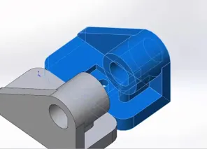
Mirror:- This feature creates copy of solid part. When this feature is applied it need plane or axis to mirror. Select the body which is to be mirror, select an axis or plane then apply feature and the mirrored part will get multibody.
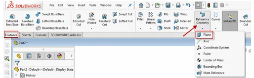
Reference geometry:- It defines the shape or form of a surface or a solid. This includes features such as planes, axes, co-ordinate system and points. This can be used according to need in a sketch.
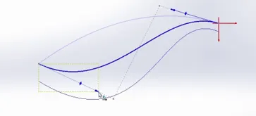
Projected curve:- The curve can be project by a sketch into a model to create a 3D curve. We can create multiple closed or open contour projected curves from a single sketch. Generally the curve can be intersection of two extruding surfaces.
Knit:- Use of knit surface tool to combine two or more faces and surfaces into one. It create a solid body when the knit surfaces form a closed volume or leave as a surface body.
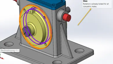
Mate:- Mate creates geometric relationship between assembly and component. When we add mates, it defines the allowable direction of linear or rotational motion of component within its degree of freedom, visualizing the assembly’s behavior.
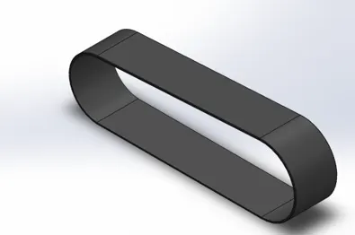
Transmission Belt:-
Features used to create the transmission belt:
- Sketch
- Extrude
- Offset
- Fillet
- Appearance
Kickstand:-
Features used to create the transmission belt:
- Sketch
- Ellipse
- Splines
- Pierce
- Loft
- Cut extrude
- Boss extrude
- Split
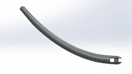
Front Fender:-
Features used to create the transmission belt:
- Sketch
- 3-point arc
- Offset
- Extend
- Trim
- Revolve
- Spline
- Fillet
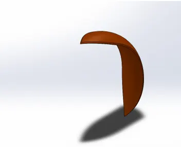
Rear Fender:-
Features used to create the transmission belt:
- Sketch
- 3-point arc
- Extend
- Trim
- Revolve
- Spline
- Fillet
- Shell
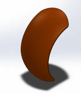
Oil Tank:-
Features used to create the transmission belt:
- Lines
- 3-point arc
- Boss extrude
- Combine
- Fillet
- Shell
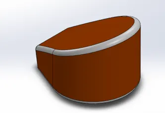
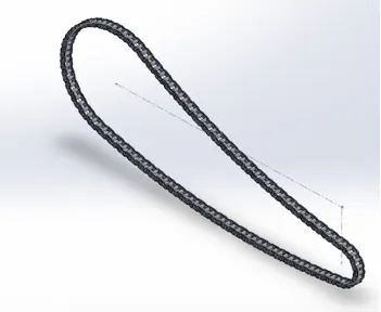
Chain Link:-
Features used to create the transmission belt:
- Sketch
- Circles
- 3point arc
- Slot
- Block
- Fillet
- Curve pattern
- Mirror
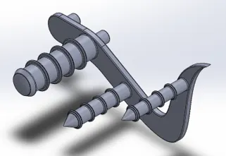
Pedal:-
Features used to create the transmission belt:
- Sketch
- Lines
- Circles
- Fillet
- Revolve
- Dome
- Chamfer
- Linear pattern
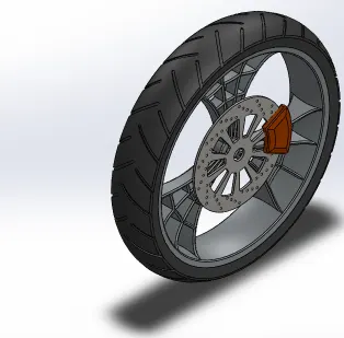
Front Wheel:-
Features used to create the transmission belt:
- Sketch
- Lines
- 3 point arc
- Sketch fillet
- Revolve
- Spline
- Extend
- Trim
- Cut extrude
- Offset
- Revolve cut
- Circular pattern
- Chamfer
- Fillet
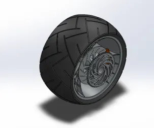
Rear Wheel:-
Features used to create the transmission belt:
- Sketch
- Lines
- 3-point arc
- Sketch fillet
- Revolve
- Spline
- Extend
- Trim
- Extrude cut
- Offset
- Revolve cut
- Circular pattern
- Chamfer
- fillet
Front Fork:-
Features used to create the transmission belt:
- Sketch
- Lines
- Revolve
- Circle
- Fillets
- Linear pattern
- Spline
- Extrude cut
- Dome
- Curve
- Sweep
- Plane
- Mirror
- Combine
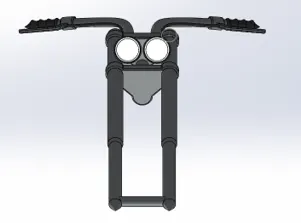
Chassis:-
Features used to create the transmission belt:
- Blueprint sketch
- Splines
- Curves
- Mirror
- Boss extrude
- Extrude cut
- Chamfer
- Dome
- Split
- Revolve
- Combine
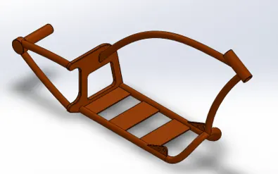
Engine:-
Features used to create the transmission belt:
- Sketch
- Blueprint sketch
- Lines
- Circles
- Boss extrude
- Fillet
- Revolve
- Dome
- Circular pattern
- Chamfer
- Linear pattern
- Mirror
- Cut extrude
- Combine
- Mirror
- Curve
- Composite curve
- Split
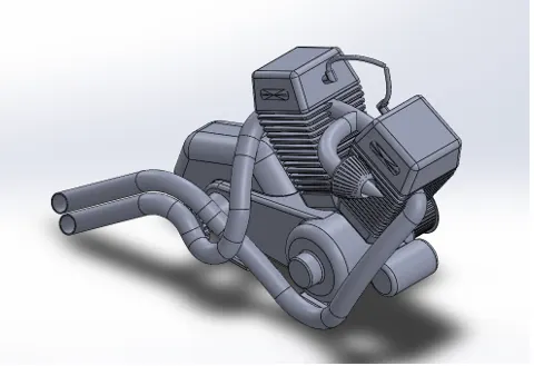
Gas Tank:-
Features used to create the transmission belt:
- Blueprint sketch
- Spline
- Surface sweep
- Surface trim
- Surface boundary
- Surface loft
- Curve
- Mirror
- Surface knit
- Surface extrudes
- Fillet
- Extrude cut
- Shell
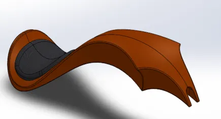
Assembly of the Chopper:-
All the parts were modelled and were imported to assemble them. In assembly mate feature is most commonly used to locate and relate the parts with one another. Chassis is main component which is inserted first and then fixed.
Decals:- A decal is something called a “transfer”, and it consists of a picture, image, pattern, or design that’s printed on metal body. We have added decals on Gas tank, Rear fender and Oil tank of chopper.
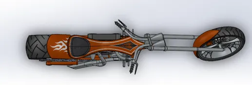
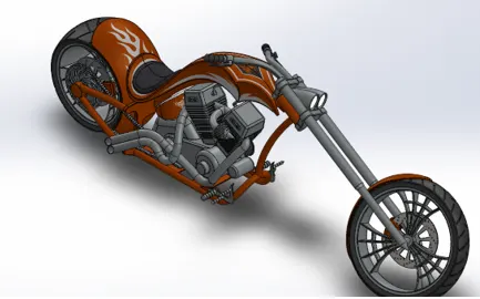
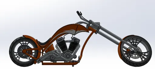
Rendering:- The term rendering comes from the graphic world where a rendering is an artistic drawing of what a new structure would look like. In Computer Aided Design (CAD), a rendering is a particular view of a realistic image.