Radar Mast & Final Assembly of Yacht
1) Design the components :
Radar Mast :
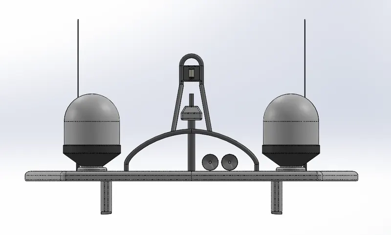
Front view Radar Mast :
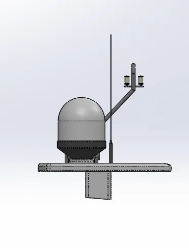
Side view Radar Mast :
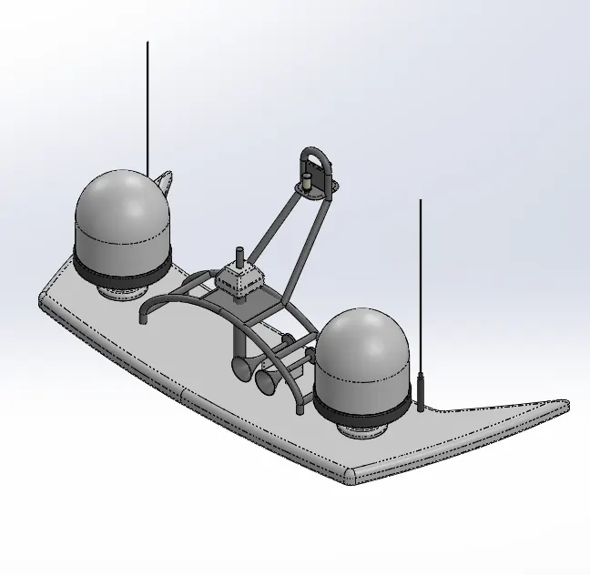
Isometric view Radar Mast :
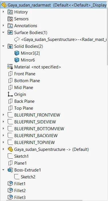
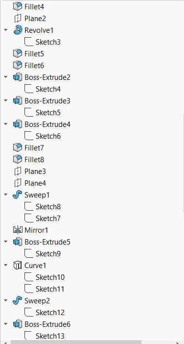
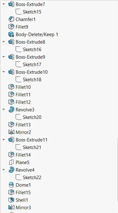
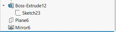
Feature tree Radar Mast :
TITLE :
Surface Modelling, Assembly and Rendering of sunseeker predator Yacht.
OBJECTIVES :
The objective of the project is to model a sunseeker predator yacht and assembling all the components of the yacht.
INTRODUCTION :
The yacht is a large and usually expensive boat used for traveling around. Solidworks is a computer aided Design software where 3D solid modeling, Assembling and Analysing the components can be done easily. In this yacht design we have modeled all the parts of the yacht except the engine. The parts are modeled individually by using the solidworks features and then they are assembled in solidworks. To get the realistic view of the yacht we use solid works visualization to look as realistic as possible.
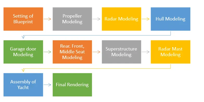
DESIGN METHODOLOGY/APPROACH :
TOOLS USED :
Extruded Surface :
This tool is used to extrude a sketch or sketch contours in one or two directions to create a surface and its extent can be defined.
Swept surface :
This tool is used is used to sweep a closed profile along an open or closed path to create a surface. To create different shapes guide curves, profile orientations, twist angles may be used.
Lofted Surface :
This tool is used to loft a surface between two or more profiles or sketches, by defining the start and end constraints and guide curves to control the shape.
Boundary Surface :
This tool is used to create surface between profiles that are tangent or have continuous curvature in all directions.
Filled Surface :
This tool is used to patch/fill a surface within a boundary which is defined by edges, sketches, or curves.
Ruled Surface :
This tool is used to insert ruled surfaces in specified directions (tangent, normal, tapered, etc). from edges. After creating surface we can trim and knit the surfaces and also remove the connecting surfaces.
Offset Surface :
This tool is used to offset surface using one or more contiguous faces. This tool creates a surface with gaps which can be repaired manually, or adjust the offset distance value and run the tool again.
Delete Face :
This tool is used to delete faces from solid bodies to create surfaces, or delete a face from the surface body. It can also be used delete and patch faces to form continuous surface, or delete and fill to replace faces with a single face.
Extend surface :
This tool is used to extend one or more edges or faces on a surface based on end condition and extension types.
Trim Surface :
This tool is used to trim a surface where it intersects with another surface, a plane, or a sketch. It is defined by trim type( standard/mutual), trim tool (sketch, surface, plane), and selecting the surfaces to remove or keep.
Knit Surfaces :
This tool is used to combine two or more adjacent, non intersecting surfaces into a single surface body provided they join at a edge. If the resulting knit surfaces encloses a volume, you can create a solid body.
Split Line :
This tool is used to project an sketch, spline or surface face onto other surfaces or planar faces to split them into multiple bodies.
Thicken :
Creates a solid feature by thickening one or more adjacent surfaces, multiple adjacent features can also be thickened if they are knitted.
Sketch :
Sketch is 2D representation of 3d models and it is created using sketch entities like line, circle, arcs, spline, polygons,etc
Offset entities :
Offset one or more sketch entities by a specified distance. If the original entity changes then the offset entity also changes when you rebuild the model.
Boss Extrude :
Extrudes a sketch or selected sketch contours in one or two directions to create a solid feature. Extrude can also be offset to specified distance.
Fillet :
Creates a rounded internal or external face along one or more edges on a solid or surface feature. Fillets can be of constant or variable size.
Edit Appearances :
Edit the appearance of the entities in the model using appearance properties such as texture mapping and colors.
Lofted Boss :
This feature adds material between two or more profiles to create a solid feature. It helps to generate complex geometries
Dome :
This feature can be used on planar or non-planar surfaces to get a closed curved surface.
Extruded cut :
This feature is used to remove materials from a solid model by extruding a sketched profile in or two directions. In multi body parts we can choose body to cut and bodies to keep.
Split :
This tool is used to project an entity onto other curved or planar surfaces. We can create multiple bodies from single body.
Revolved Boss :
Revolves a sketch or selected contours around a axis to create a solid feature. We can define axis of revolution and direction.
Trim Entities :
Trims or extends a sketch entity to be coincident to another or deletes a sketch entity
Shell :
Shell feature hollows the part and leaves the face open which you select and creating thin walled features on the remaining surfaces. If a face is not selected then a closed hollow model is created
Mirror :
Mirrors features, faces, and bodies about a plane or a planar face. In assemblies you can mirror assembly features
Combine :
Using the combine tool we can add, subtract, or find common area of two different bodies. A multi body part is required for this feature. In this model two different boss extrudes common area was chosen
Linear pattern :
This feature patterns features, faces, and bodies in one or two linear directions. This can be defined by selecting reference geometry and instances can be skipped.
Chamfer :
This feature is used to create sloped or angled corner or edge. It can be defined by either choosing distance distance or angle distance option.
Projected curves :
This feature is used to create 3D curve from 2D curves from two different curves.
Swept Boss :
This feature sweeps a closed profile along an open or closed path to create a closed surface. A wide variety of shapes can be created by using the options like guide curves, twist and profile orientation options.
PARTS MODELLED :
PROPELLER :
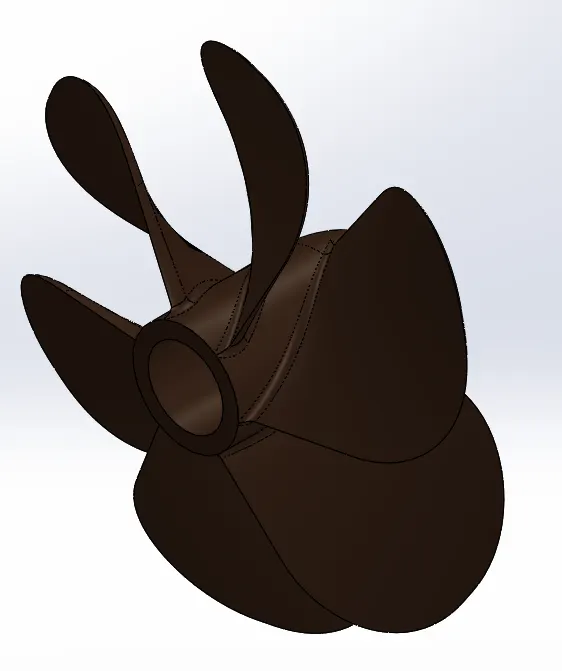
TOOLS USED :
- Sketch.
- Revolve.
- Reference Geometry (plane).
- Lofted Boss.
- Fillet.
- Extruded Cut.
- Circular Pattern.
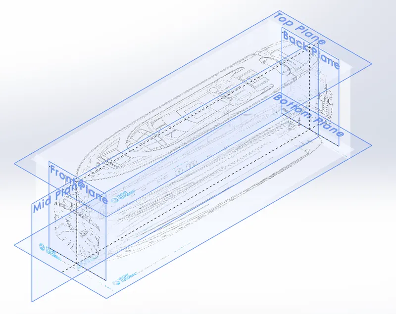
BLUEPRINTS :
RADAR :
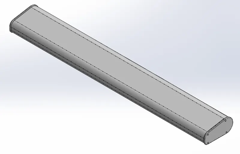
TOOLS USED :
- Sketch.
- Extruded Boss.
- Fillet.
- Extruded Cut.
- Sketch pattern.
- Split line.
- Mirror.
FRONT SEAT :
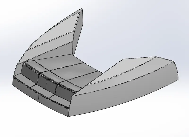
TOOLS USED :
- Blue print set up.
- Sketch.
- Swept surface.
- Trim surface.
- Filled surface.
- Lofted surface.
- Knit surface.
- Chamfer.
- Revolve.
- Extruded cut.
- Fillet.
- Mirror.
- dome.
MIDDLE SEAT :
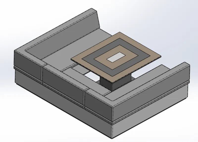
TOOLS USED :
- Blue print set up.
- Sketch.
- Extruded boss.
- Reference geometry (plane).
- Chamfer.
- Fillet.
- Mirror.
- Extruded cut.
REAR SEAT :
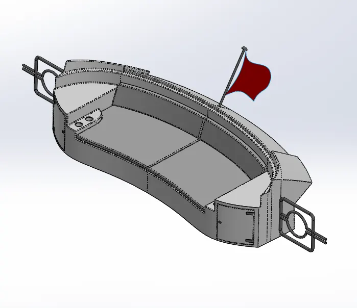
TOOLS USED :
- Blue print set up.
- Sketch.
- Swept surface.
- Trim surface.
- Ruled surface.
- Lofted surface.
- Extend surface.
- Knit surface.
- Extruded boss.
- Extruded cut.
- Chamfer.
- Fillet.
- Reference geometry (plane).
- Offset surface.
- Swept boss.
- Mirror.
- Revolved boss.
HULL :
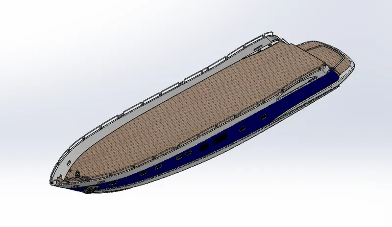
TOOLS USED :
- Blue Print set up.
- Sketch.
- Projected Curves.
- Lofted Surface.
- Trim Surface.
- Knit surface.
- Surface Extrude.
- Surface Fill.
- Shell.
- Extruded Boss.
- Extruded Cut.
- Fillet.
- Chamfer.
- Reference Geometry(plane).
- Swept Boss.
- Revolved Boss.
- Dome.
- Helix/spiral curve.
- Linear Pattern.
- Extrude thin.
- Mirror.
- Combine.
- Split line.
GARAGE DOOR :
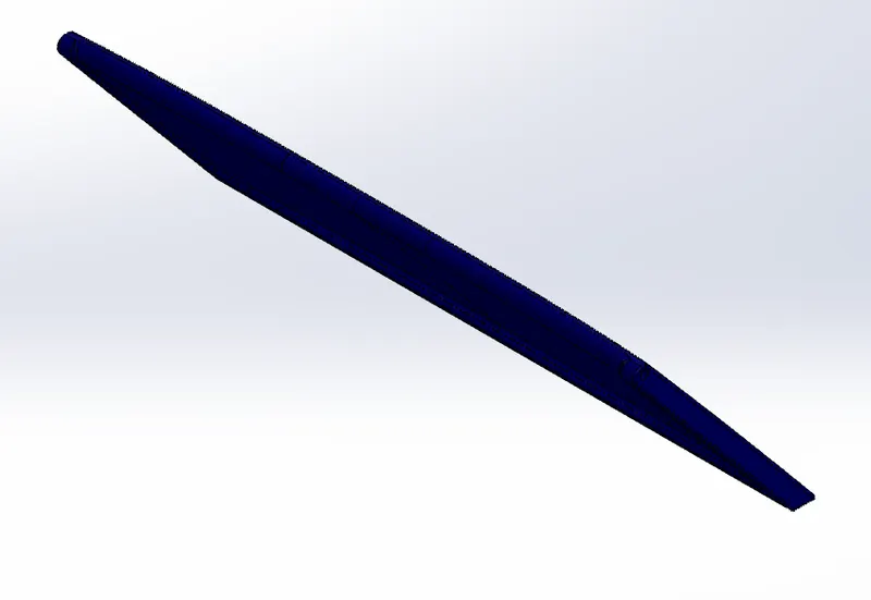
TOOLS USED :
- Sketch.
- Cut Extrude.
- Shell.
- Fillet.
- Mirror.
- Reference Geometry(plane).
SUPERSTRUCTURE :
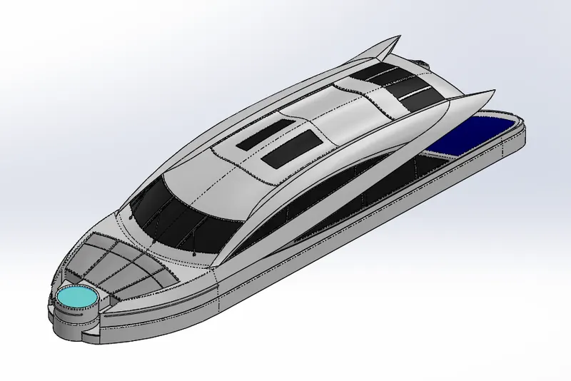
TOOLS USED :
- Blue print set up.
- Sketch.
- Extruded surface.
- Offset entities.
- Trim.
- Reference geometry (plane).
- Swept surface.
- Ruled surface.
- Trim surface.
- Projected curve.
- Filled surface.
- Knit surface.
- Lofted surface.
- Extend surface.
- Extruded boss.
- Fillet.
- Offset surface.
- Thicken.
- 3D sketch.
- Dome.
- Swept boss.
- Extruded cut.
- Split line.
- Extruded surface.
- Mirror.
- Chamfer.
RADAR MAST :
TOOLS USED :
- Blue print set up.
- Sketch.
- Extruded boss.
- Fillet.
- Revolved boss.
- Reference geometry (plane).
- Swept boss.
- Mirror.
- Chamfer.
- Dome.
YACHT ASSEMBLY :
FRONT VIEW OF YACHT :
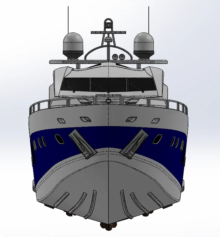
SIDE VIEW OF YACHT :
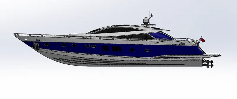
TOP VIEW OF YACHT :
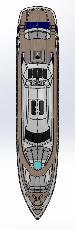
CAMERA SETUP VIEW :
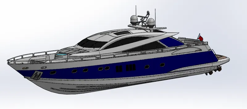
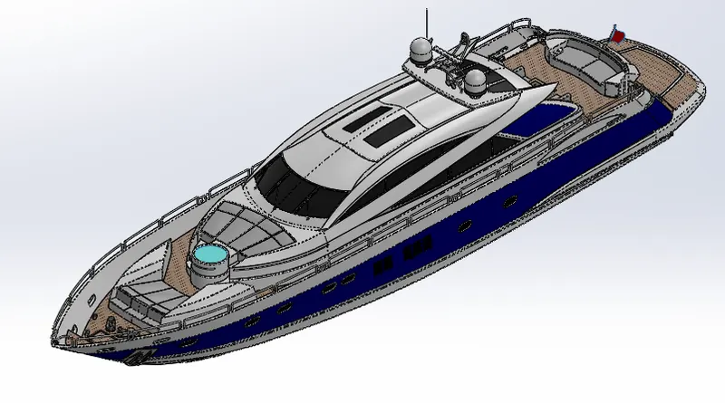
ISOMETRIC VIEW OF YACHT :
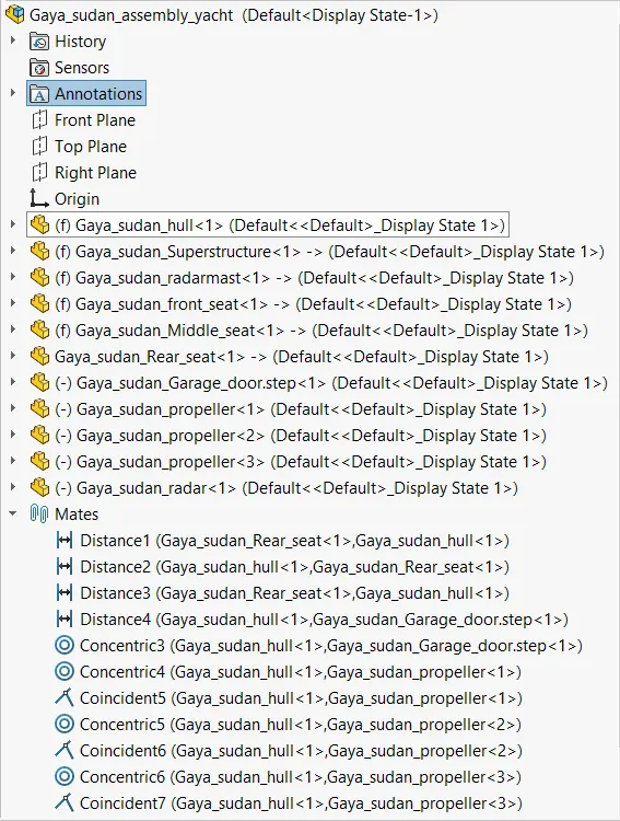
FEATURE TREE OF YACHT :

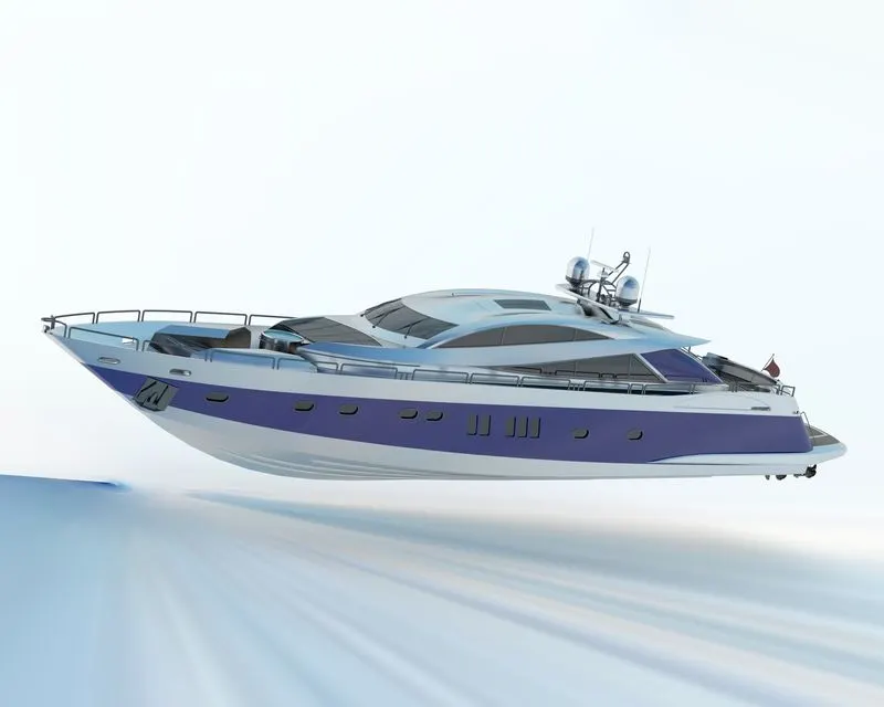
SOLIDWORKS VISUALIZE :
This software is used to create a photo quality content in the best way. We can be able to form animataions, interactive web content and virtual reality.
RENDERED IMAGES :
CONCLUSION :
I have learnt how to model sunseeker predator yacht in solid works and I have learnt how to design using surface modelling commands. I have learnt solid works in the industrial manner and I've got hands on experience in modeling a complex design. This has helped me in enhancing my design skills.