Week -2
1) Make a Simulink model of Doorbell using solenoid block with the following details :
when the switch is closed the electromagnet receives electrical power from the battery and pulls the metal arm to hit the bell producing sound. Create a situation where the switch is closed for 2 seconds and then released. Observe the physical movement of the plunger.
SIMULINK MODEL :
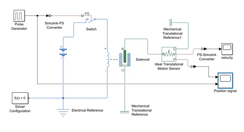
EXPLANATION :
1) From the above circuit of a door bell, we know that we need a switch, solenoid, battery and a plunger.
2) Now a 'solenoid block' is taken to represent a solenoid in the model then to represent the battery i have taken battery block from the library.
3) Now both the 'solenoid block' and 'battery block' is connected each other via positive and negative terminal.
4) A 'switch block' is placed between solenoid and battery block its also connected with both the blocks.
5) Now the switch needs to be operated we need to provide a physical signal through PS port in the switch block. The physical signal should be greater than the threshold of the switch, for switch being closed, or else it will be open.
6) The battery, switch and solenoid path is connected into 'electrical reference block' it represents earthing of the circuit. 'Electrical reference block should be connected with negative port of the 'battery block'.
7) The 'solenoid block','R' and 'C' are two variables which represent plunger and fixed point respectively.
8) Now the 'R' is connected to 'R' of 'ideal Translation motion sensor block' which senses the position of the plunger in the 'solenoid block' and gives the output.
9) In 'ideal translation motion sensor block' the outputs are given as 'V' and 'P' which represent the velocity and position of the plunger.
10) Now 'C' in the 'ideal translation motion sensor block' is a mechanical translation conserving port, it means that the mechanical process starts from 'R' and ends at 'C' and again it starts at 'R' and the cycle goes on.
11) So 'C' in the 'ideal translation motion sensor block' is connected to a 'mechanical translation reference' which represents a fixed point.
12) 'C' of solenoid block is also connected to the same 'mechanical translation reference' as fixed point for the solenoid.
13) To give physical signal for operating the switch we used a 'pulse generator block' which generates a continous square pulse.
14) From the 'ideal translational motion sensor' is connected to PS simulink converter then it is connected to the 'scope block' which will generate the graph for change in position of plunger from port 'P'.
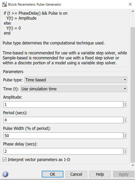
15) I have given as the period valuse is '4', pulse width as '50', phase delay as '2' and amplitude by default is '1'. The pulse will be '0' initially and till '2' second the pulse will be zero because of phase delay is given as '2'. After that the pulse will start from 0 to 1 since the amplitude is '1'.
16) From starting to ending of the pulse it will take 4 secs of time in which only for 2 secs the amplitude will be one and for the time rest of the time it will be zero. After the 4 seconds again the pulse will be generated and it continoes.
17) This pulse generator is connected to the 'Simulink PS converter' then to the switch and it is also connnected to the 'scope block' to see how the pulse is generated.
Position signal scope :
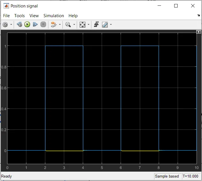
18) This shows how the pulse is generated in the X axis represents time and Y axis represents amplitude.
19) This shows when the amplitude is one the switch is closed and whenit is zero the switch is open. The objective of the plunger is to see the change in position of plunger when the switch is closed for 2 seconds so that the amplitude as 1or 2 seconds in the pulse generator by making the pulse width half of the period in the inputs for the pulse generator block.
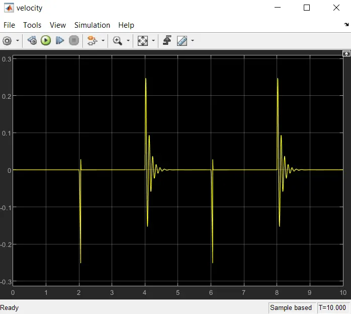
20) In the velocity scope x axis represents time in seconds and y axis represents position of plunger.
21) In the above figure initial position of the plunger is at '0', as from the pulse generator block the pulse is generated at 2, so the position of the plunger is also changing at time 2 seconds and time till which the pulse amplitude is 1, till that time the plunger is also at the same position after the change from the initial position.
2) Use a thermistor to sense the temperature of a heater & turn on or turn off the fan as per below conditions:
Temperature source: 20 °C from 0 to 10 seconds, 27 °C from 10 to 30 seconds, 23 °C from 30 to 50 seconds. Fan conditions: ON if the temperature above 25 °C, OFF otherwise.
SIMULINK MODEL :
EXPLANATION :
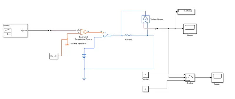
1) To create a Fan model using thermistor we need a thermister, battery, resistor, voltmeter, a logical switch are the basic components in the circuit we needed in the simulink model.
2) To represent a thermistor a 'thermistor block' is taken and placed in the simulink model. Now to represent a battery a 'battery block' is created and taken the positive port of this block is connected to the positive port of the Thermistor block.
3) A 'Resistor block' is taken from the library browser and its positive port is connected to negative port of the 'thermistor block'. The negative port of resistor block is connected to the negative port of the battery block. Now a electrical reference block is connected near the negative terminal of the battery block this gives earthing.
4) A 'voltage sensor block' is connected parallel to the resistor block, because to measure the voltage accross the component, voltmeter should always been connected parallel to the component.
5) We need the fan to get ON and OFF at different temperatures. To provide temperature we have used 'Controlled temperature source block' which only gives specified temperature as output even though heat flow is more.
6) To give different termperatures 'controlled temperature source block' is used. To send these signal I have used a 'signal builder block' which allows any type of signals to send.
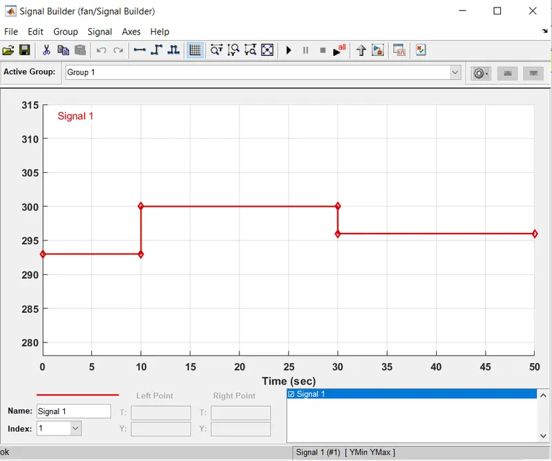
7) Double click on the signal builder block so that we can customise the signal builder block according to the requirement. In the top there is a signal click on that select new and then custom. Now we can give the time in seconds in x axis and temperature in y axis.
8) We have to convert these signals into physical values, to do that 'simulink PS converter block' is used. Now output of voltage sensor block is connected to a 'scope block' before connecting the second scope a 'simulink PS converter block' is used to convert the physical value to simulink value.
9) The voltage is changing with repect to temperature. Using this condition of the fan can be set to ON or OFF.
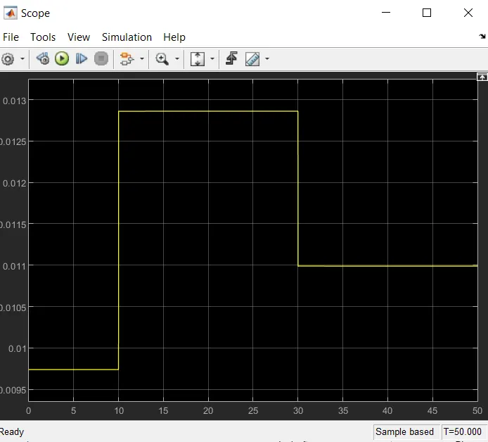
10) We see that time is changing from 0 to 10 seconds when temperature is 293K voltage is between 0.0095 to 0.01 and from time 10 to 30 seconds temperature is 300k voltage is between 0.0125 and 0.013 and from time 30 to 50 seconds temperature is 296k and voltage is nearly to 0.011.
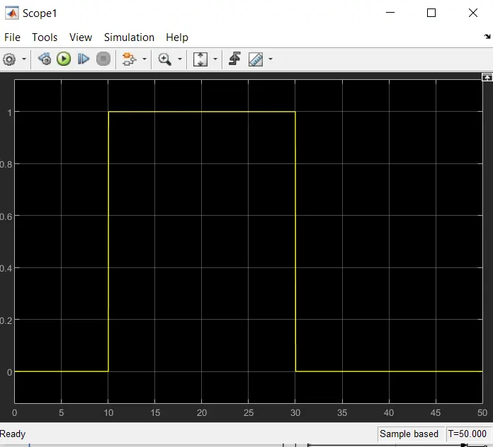
11) As mentioned the fan should be ON when the temperature is above 25 degree celcius, when the voltage is above 0.011 the fan should be ON and when the voltage is below 0.011 the fan should be OFF.
12) The above logic is used to ON and OFF the fan. To do this switch block is used to reroute the signal according to the conditions provided.
OUTPUT OF SWITCH BLOCK :
OUTPUT OF VOLTAGE SENSOR BLOCK :