Radar Mast & Final Assembly of Yacht


SKILL LYNC
PROJECT REPORT
MODELLING OF YACHT ON SOLIDWORKS
BY, AMIT MINTRI
INTRODUCTION:
The project gives the detailed instruction about the designing of different parts of Yacht like
- Propeller
- Radar
- Blueprint setup
- Hull
- Garage door
- Front seat
- Middle seat
- Rear seat
- Superstructure
10.Radarmast
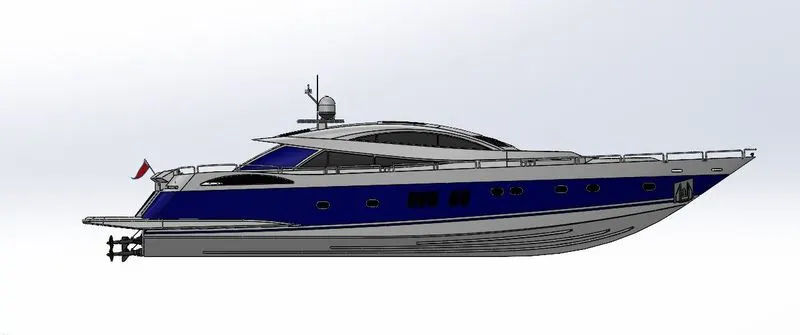
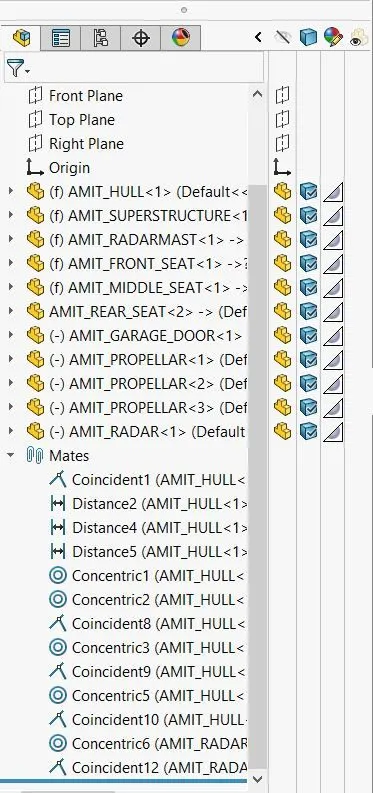
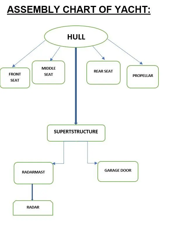
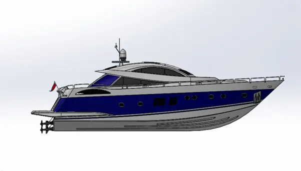
And also provide instruction about the assembly of all these parts using solid works. It also explains the rendering of designed model which makes it look more realistic and presentable.
MODELLING FEATURES/COMMAND
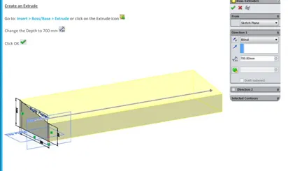
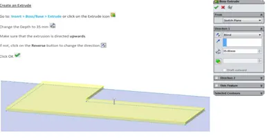
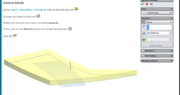
EXTRUDE: Extrude tool is used to extend a sketched profile in directions as either a thin feature or a solid feature. It is basically a feature which converts 2D sketch into a 3D model. An extrude operation can either add material to a part or remove material from a part. It is of two types extrude boss and extrude cut. Extruded Boss feature adds material to the part model and extrude cut remove material from the part model. For extrude 2D sketch has to be closed.
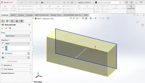
FIGURE 1: EXTRUDE BOSS
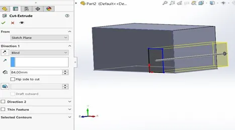
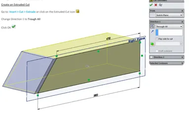
FIGURE 2: EXTRUDE CUT
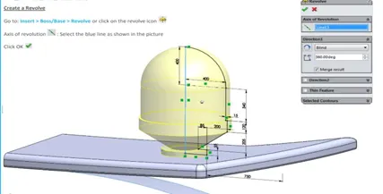
REVOLVE: It is used to revolve a 2D sketch along an choose axis and makes it a 3D model. To create a revolve create a new sketch and create all solid sketch geometry on one side. Choose revolve from the features and pick the axis you want to use for the revolve. You can specify direction and angle also. Like extrude it is also of two types Revolve boss and Revolve cut. Revolve boss adds material by revolving one or more profiles around a centerline and revolve cut remove material. The revolve feature can be a solid, a thin feature, or a surface.
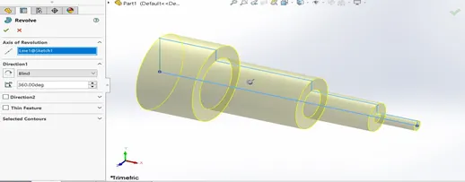
FIGURE 3: REVOLVE
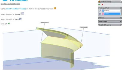
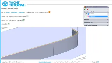
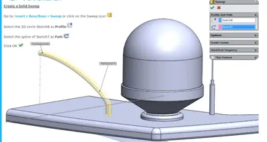
SWEEP: Sweep is the one feature in Solid works that helps sweep a closed profile along a closed or open path. It is used to make long pipe or tube-like structure. To create a sweep first sketch a closed, non-intersecting profile on a plane or a face. If we use guide curves then we have to create the path for the profile using a sketch, existing model edges, or curves.
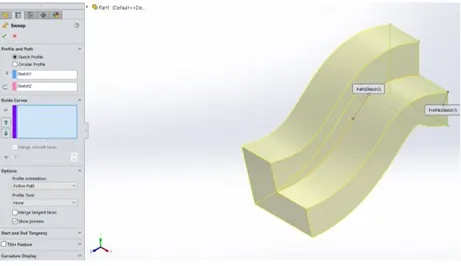
FIGURE 4: SWEEP
FILLET: Creates a rounded internal or external face on the part. You can fillet all edges of a face, selected sets of faces, selected edges, or edge loops. Radius are specified for the fillets.
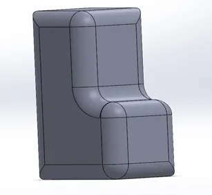
FIGURE 5: FILLET
CHAMFER: A chamfer is the sloped or angled edges or corners of a part design. It is an antonym of the fillet. Instead of having a curved shape, a chamfer is straight and has a sharp angle. If your design requires sharp corners to be efficient for its purpose, you should choose chamfer over the fillet.
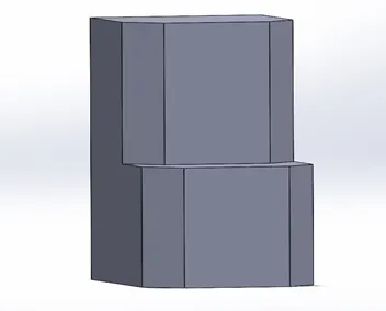
FIGURE 6: CHAMFER
SHELL: The Shell command allows you to define a wall thickness and automatically hollow the part, while allowing faces to be removed as needed. If no faces are specified to be removed during a Shell feature, the part will be hollow, but this can only be seen by creating a cross section of the part.
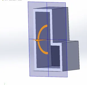
FIGURE 7: SHELL
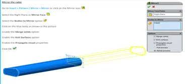
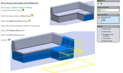
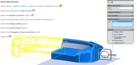
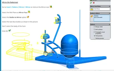
MIRROR: Mirroring is another way that SolidWorks can create a copy of an existing object. We must choose a plane to mirror parts. In most cases, we will have to create your own plane to have the mirror done.
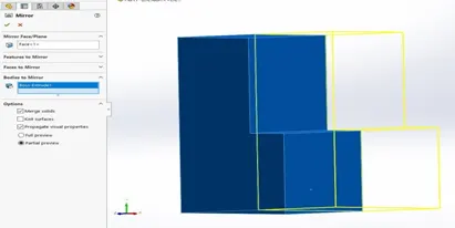
FIGURE 8: MIRROR
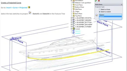
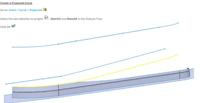
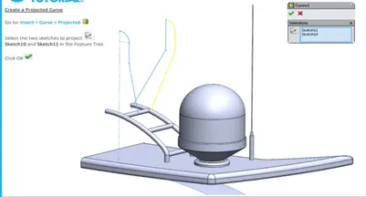
PROJECTED CURVE: To project existing curves onto planes or surfaces in a specified pierce direction. Laying down. To lay down existing curves onto a surface without changing the length and shape of the curves. The original curves and the curves laid down are matched by associating a point on the curve with a point on the surface.
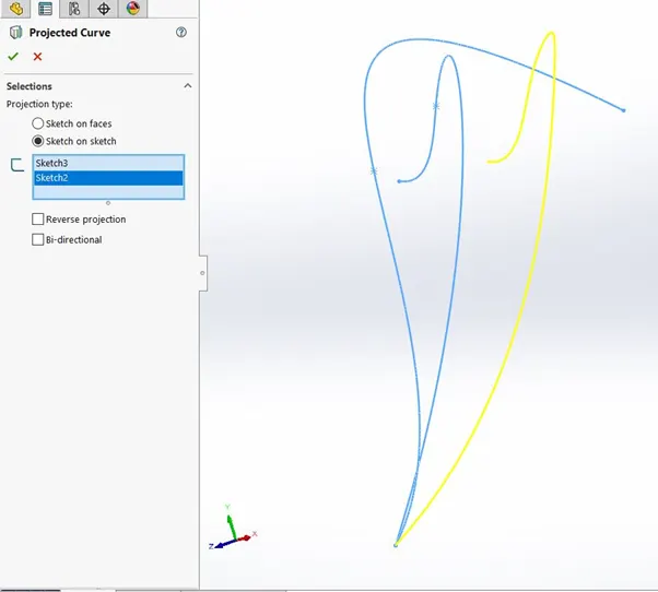
FIGURE 9: PROJECTED CURVE
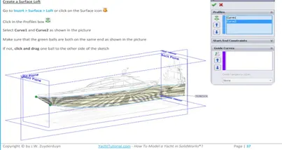
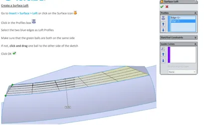
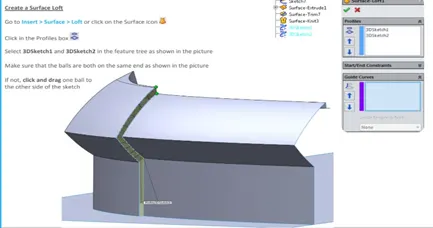
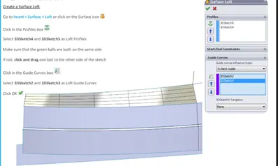
SURFACE LOFT: Loft Surfaces are surfaces generated by multiple 3D Curves or existing edges creating a smooth tangency between the selected curves. Match Points are created between each selection denoting the orientation and path of the loft surface. Users can change the match point during creation by deselecting the curve and selecting at the opposite end of the curve. An option to have the loft surface to become a closed loop is available at right-click. Guide Curves can be added to help shape the loft during creation or editing.
To create a lofted surface:
- Create a plane for each profile section of the loft. The planes do not need to be parallel.
- Sketch the section profiles on the planes. You can create all section and guide curve sketches inside a single 3D sketch.
- If necessary, create guide curves.
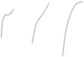
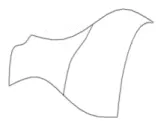
Profiles Profiles with Guide Curves
- Click Lofted Surface (Surfaces toolbar) or Insert > Surface > Loft.
- Set the Property Manager options.
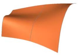
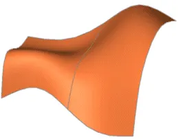
Simple loft Loft using guide curve
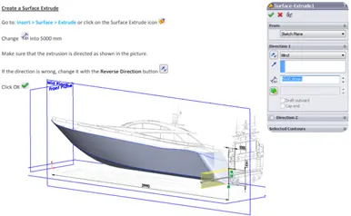
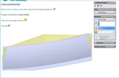
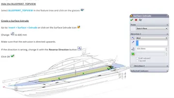
SURFACE EXTRUDE: We can create extruded surfaces from models that include 2D or 3D faces and knit the extruded surfaces to surrounding features.
- Click Insert > Surface > Extrude.
- Select a face:
We can select either a surface or the face of a solid body.
- Select other faces to define the extrude as required.
- Select the end condition.
- For 3D faces, select a plane, edge, 2D face, or sketch line to define the direction of extrusion .
Select a plane to define an extrude direction normal to the plane.
- To remove the faces defining the extrude from the model after extruding, click Delete original faces.
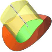
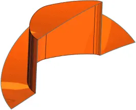
The green area is the face defining the extrude. The resulting model is hollow where the face was deleted.
- To create a single body from the extrude when faces are deleted, select Knit result .
Clearing Knit result produces two separate bodies.
- Set other options and click ok.
SURFACE OFFSET: The Offset Surface tool creates a new surface body from an existing set of faces. The faces may be solid or surface faces.
To create an offset surface:
- Click Offset surface.
- In the Property Manager:
- Select surfaces or faces in the graphics area for Surface or Faces to Offset.
To select the entire model, click Edit > Select All.
- Set a value for Offset Distance.
we can create an offset surface with a distance of zero.
- Select Flip Offset Direction to change the direction of the offset.
- Click OK
EXTEND SURFACE: We can extend a surface by selecting an edge, multiple edges, or a face.
To extend a surface:
- Click Extended Surface.
- In the Property Manager:
- Under Edges/Faces to Extend, select one or more edges or faces in the graphics area for Selected Face/ Edges.
For edges, the surface extends along the plane of the edge. For faces, the surface extends along all edges of the face except those connected to another face.
- Select an End Condition type:
- Distance
- Up to point
- Up to surface
- Select an Extension Type:
- Same surface
- Linear
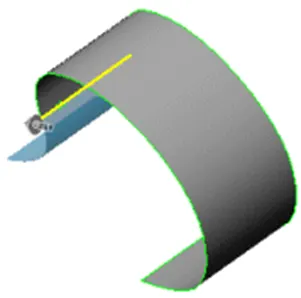
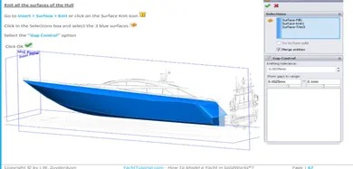
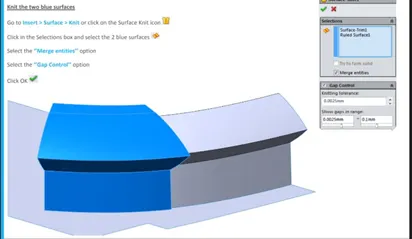
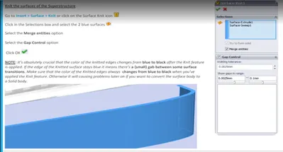
KNIT SURFACE: We use the Knit Surface tool to combine two or more faces and surfaces into one.
For knitting
- Edges of the surfaces must be adjacent and not overlapping.
- Surfaces do not need to be on the same plane.
- Select the entire surface body, or select one or more adjacent surface bodies.
- Knit surfaces absorb the surface bodies you used to create them.
- Create a solid body when the knit surfaces form a closed volume, or leave as a surface body.
- Select Merge entities to merge faces with the same underlying geometry.
- Select Gap Control to view the gaps or modify the knitting tolerance
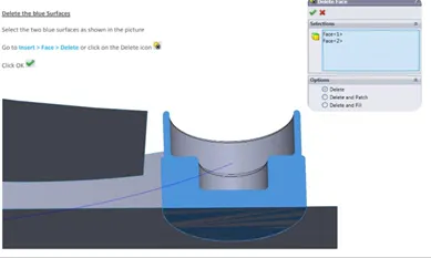
DELETE FACE: we can delete faces from surface and solid bodies.
With Delete Face tool, we can do the following:
|
Delete |
Deletes a face from a surface body, or deletes one or more faces from a solid body to create surfaces. |
|
Delete and Patch |
Deletes a face from a surface body or solid body and automatically patches and trims the body. |
|
Delete and Fill |
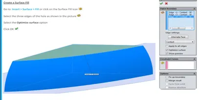
Deletes faces and generates a single face to close any gap. |
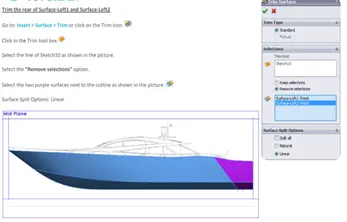
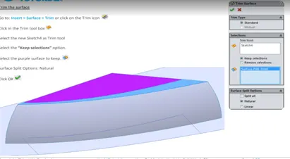
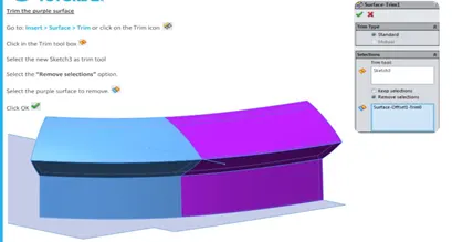
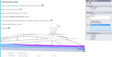
Trim Surface: we can use a surface, plane, or sketch as a trim tool to trim intersecting surfaces. We can also use a surface in conjunction with additional surfaces, as mutual trim tools.
To trim a surface:
- Create two or more surfaces that intersect at one or more points, or create a surface that intersects with a plane or has a sketch on its face.
- Click Trim Surface.
- In the Property Manager, under Trim Type, select a type:
- Standard: Trims surfaces using surfaces, sketch entities, curves, planes, and so on.
- Mutual: Trims multiples surfaces using the surfaces themselves.
- Under Selections, choose from these options:
- Trim tool (available with Standard selected under Trim Type). Select a surface, sketch entity, curve, or plane in the graphics area as the tool that trims other surfaces.
- Surfaces (available with Mutual selected under Trim Type). Select multiple surfaces in the graphics area for Trimming Surfaces to use to trim themselves.
- Select a trim action:
- Keep selections.
- Remove selections.
MODELLING OF PARTS
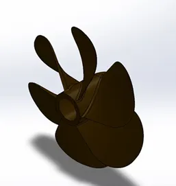
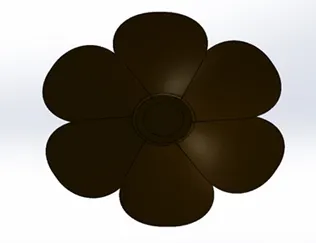
- PROPELLAR: Boat propellers include blades that turn on a shaft, which is powered by the motor. Propellers can have 3, 4, or 5 blades. Propeller blades displace water, to create the forces that move a boat forward. The basic propeller shaft creates the torque, or energy required to turn the blades. The purpose of the propeller is to provide a method of propulsion so the aircraft is able to move forward through the air. The propeller itself consists of two or more blades connected together by a central hub that attaches the blades to the engine shaft.
We design the propellar with the help of features like
- Revolve
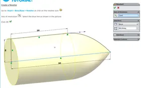
- loft
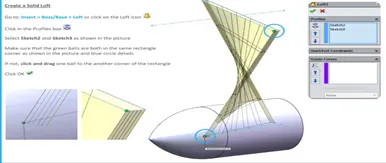
- cut extrude
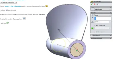
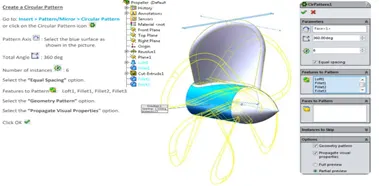
- circular pattern
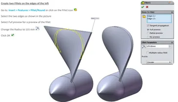
- fillet
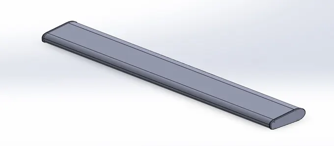
- RADAR: It is a precious navigation aid, especially in situations of reduced visibility. It can be used to know the position and distance of other boats, other obstructions such as rocks and buoys and the coast. For example, in fog, radar can be used to avoid collisions. It can be used to detect aircraft, ships, spacecraft, guided missiles, motor vehicles, weather formations, and terrain.
The features we used during the design of radar are
- Boss extrude
- Mirror
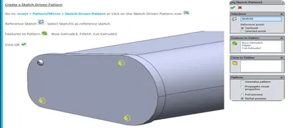
- Sketch pattern
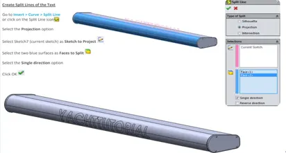
- Split line
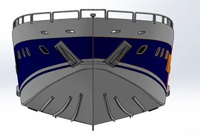
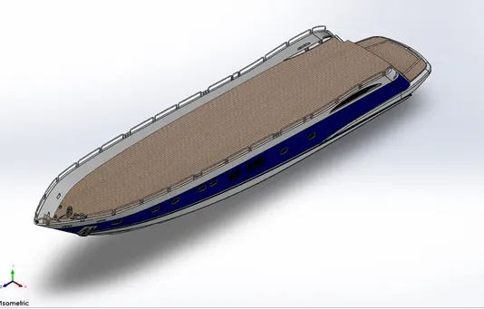
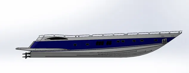
- HULL: A hull is the watertight body of a ship, boat, or flying boat. The hull may open at the top, or it may be fully or partially covered with a deck. Atop the deck may be a deckhouse and other superstructures, such as a funnel, derrick, or mast. The line where the hull meets the water surface is called the waterline. The hull of a ship is the most notable structural entity of the ship. To define the hull, it can be said that it is the watertight enclosure of the ship, which protects the cargo, machinery, and accommodation spaces of the ship from the weather, flooding, and structural damage.
In this modelling a lot of features are used.
- Projected curve
- Surface loft
- Surface extrude
- Surface trim
- Surface knit
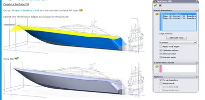
- Surface fill
- Extrude boss
- fillet / chamfer
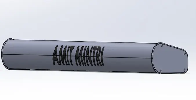
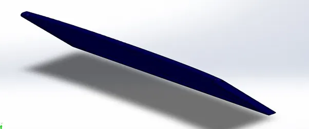
- GARAGE DOOR: Features used are
- Extrude cut
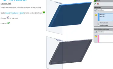
- ShelL
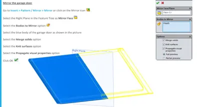
- Mirror
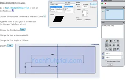
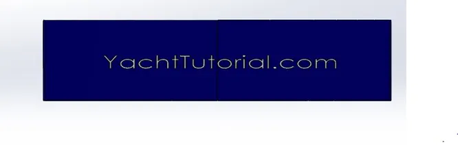
- Creating text
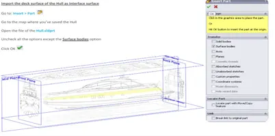
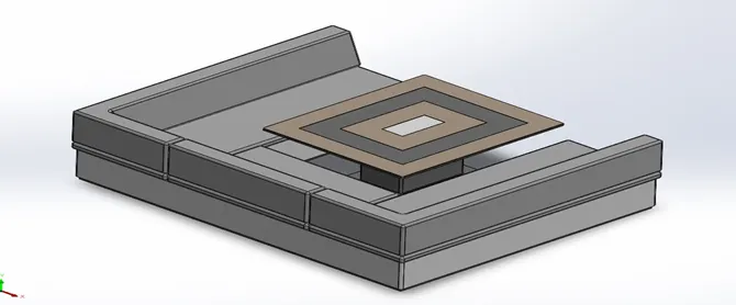
- FRONT SEAT: mostly used command during modelling of are
- Insert part
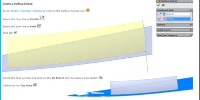
- Surface sweep
- Surface extrude
- Surface trim
- Surface fill
- Surface loft
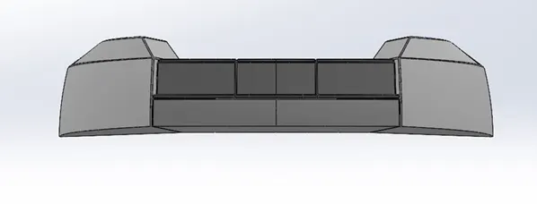
- MIDDLE SEAT: mostly used command used are
- Insert part
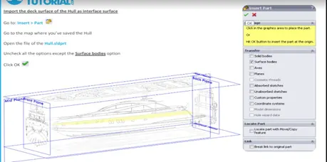
- Boss extrude
- Mirror
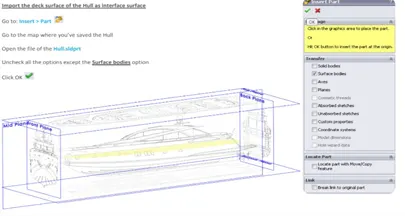
- REAR SEAT: Mostly used feature are
- Insert part
- Surface sweep
- Surface offset
- Surface trim
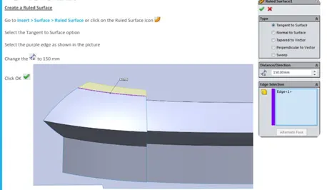
- Ruled surface
- Surface knit
- Mirror
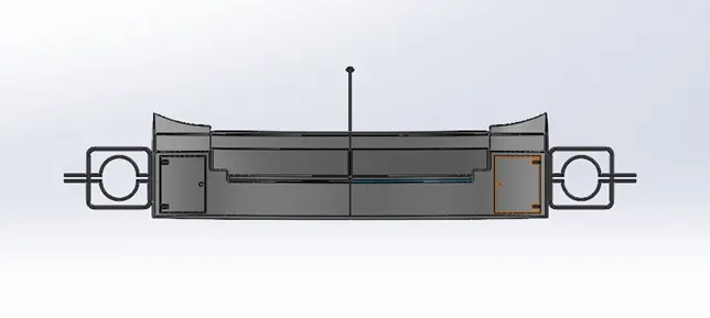
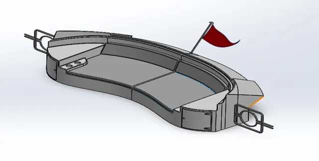
- SUPERSTRUCTURE: A superstructure is an extended construction of any building or platform that rises above the rest of the building or platform in a distinct manner. The word comes from a combination of two Latin words, the Latin prefix ‘super’ means in addition or above or in excess of, whereas the stem word ‘structure’ means to build or to heap up. Thus, superstructure means to add a construction to an already existing structure. In ships this is the name given to the part of the ship that emerges from the deck. The size of the superstructure has a great influence on the mobility of the vessels. They are designed in a manner, so that, they add value and hinder the speed and mobility in the least. The superstructure is mostly designed in fashion as well. This is because it is the most easily visible part of the ship, in fact it is the identification of the ship, and so the designers try to provide it with the identity that is unique.
In this modelling a lot of features are used like
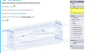
- Insert part
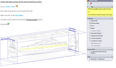
- Surface extrude
- Surface sweep
- Surface knit
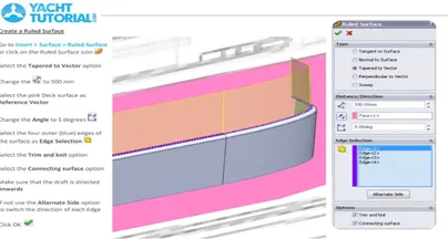
- Ruled surface
- Surface trim
- Projected curve
- Surface loft
- Delete face
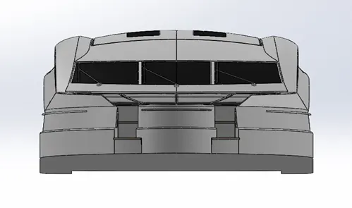
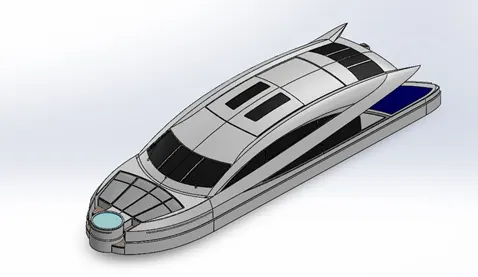
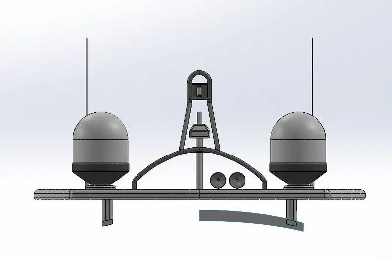
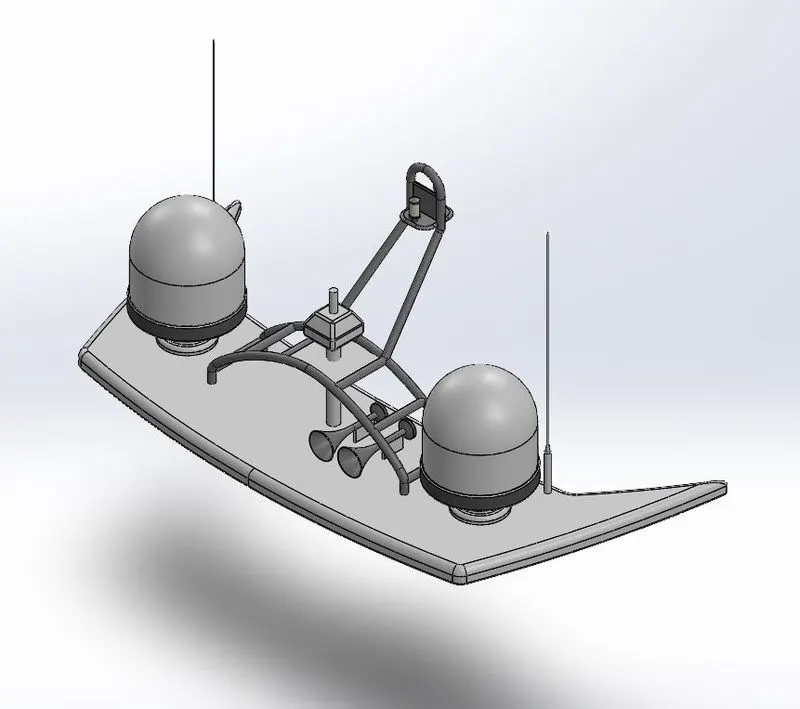
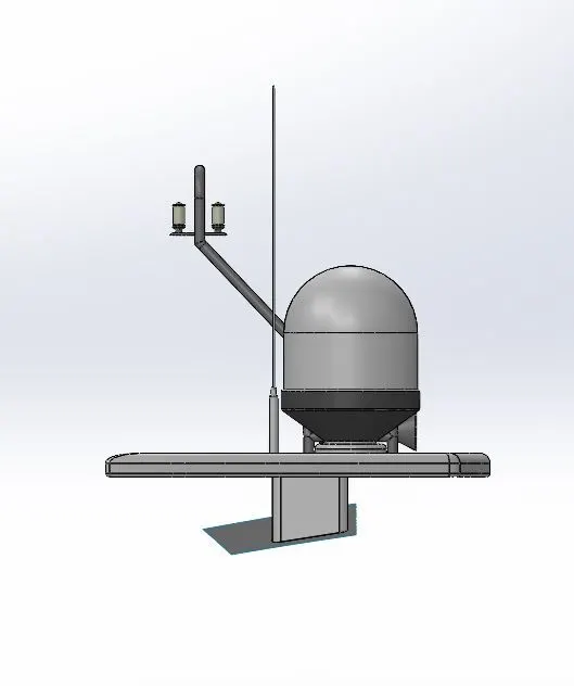
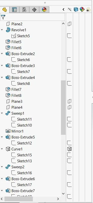
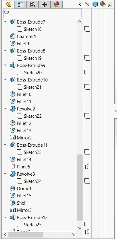
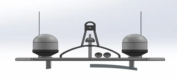
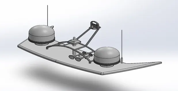
- RADARMAST: mostly used command are:
- Insert part
- Boss extrude
- Revolve
- Sweep
- Projected curve
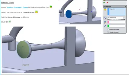
- Dome
- Mirror
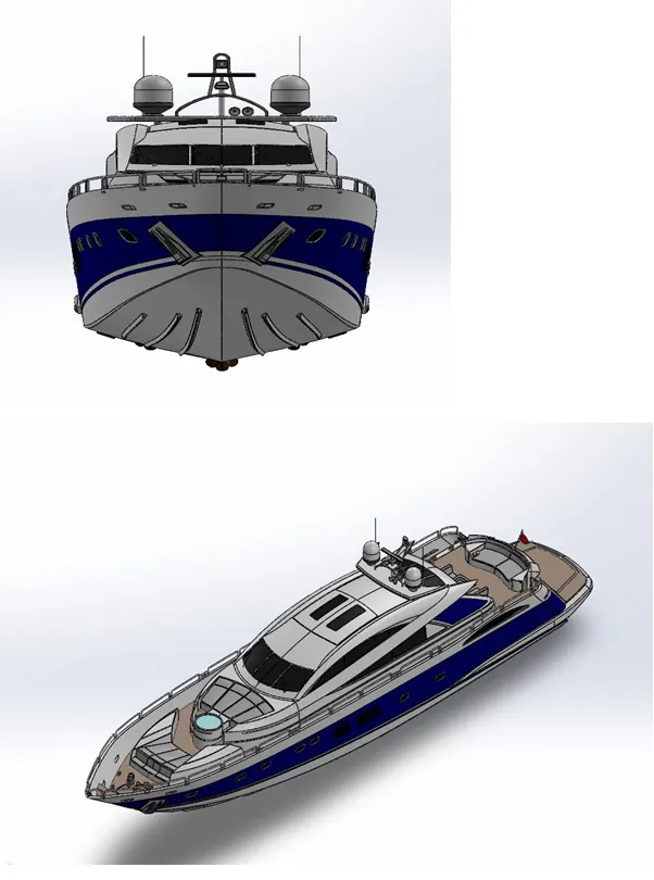
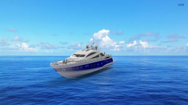
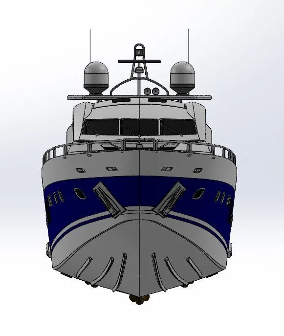
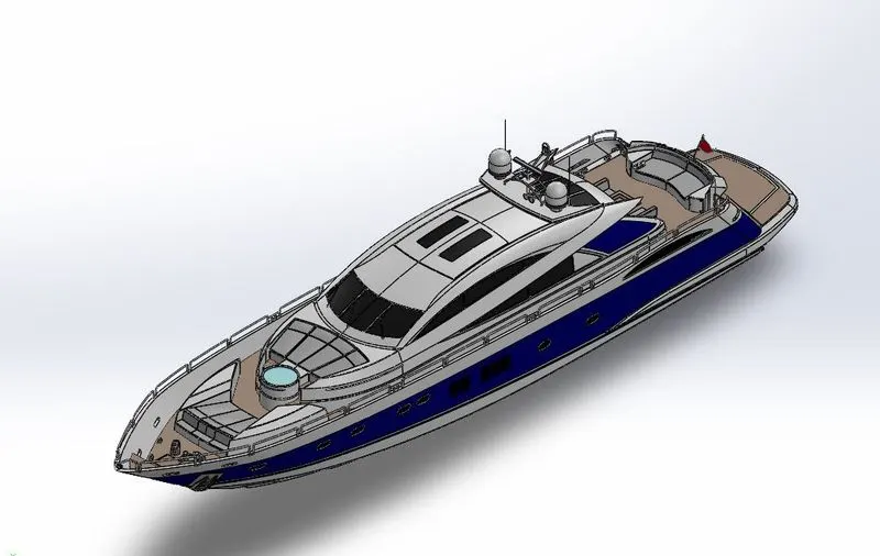
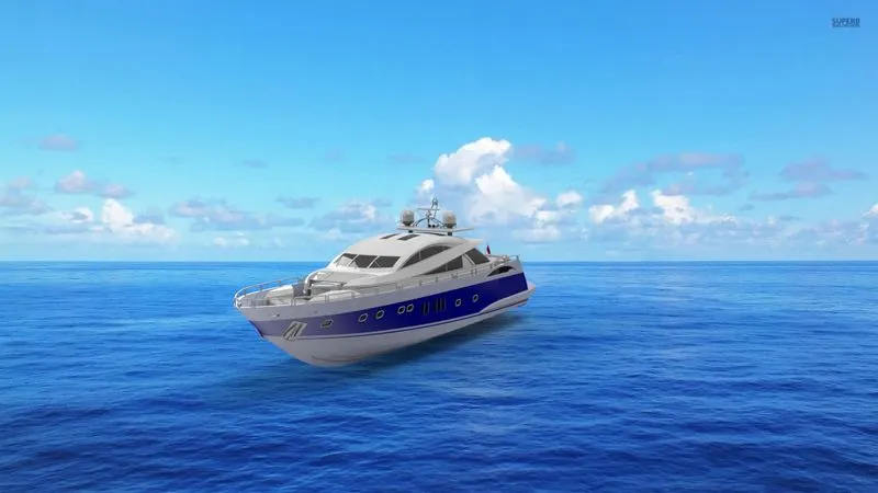
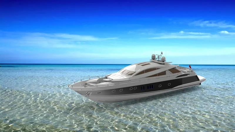
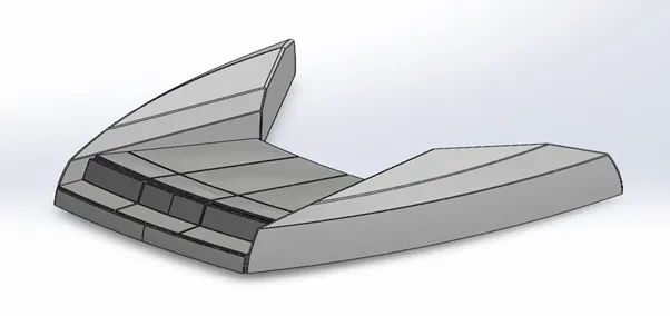
At last rendering is done to make design more prensentable, here are some redered images:

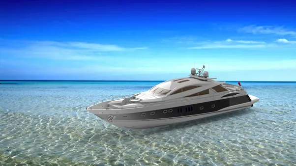


CONCLUSION:
All the parts of the yacht are modelled and assembled together successfully using solid works
We have used a lot of Solidworks feature command during modelling of yacht and after that rendering is done.