Photo Realistic Rendering
SKILL LYNC
PROJECT REPORT
MODELLING OF AMERICAN CHOPPER ON SOLIDWORKS
BY, AMIT MINTRI
INTRODUCTION
The project gives the detailed instruction about the designing of different parts of American chopper like transmission belt, kickstand, chassis, engine, gas tank, oil tank, chain, pedal, wheels, fenders, front fork and also provide instruction about the assembly of all these parts using solid works. It also explains the rendering of designed model which makes it look more realistic and presentable.
Solid works is a solid modeling computer-aided design and computer-aided engineering program, is one of the most popular software options for us design engineers. SOLIDWORKS was developed by MIT graduate Jon Hirsch tick and was bought by Dassault Systems in 1997.solidworks has lot of features and lots of modelling command, here we will learn some of these commands which are mostly used in the designing of American chopper.
MODELLING FEATURES/COMMAND
EXTRUDE: Extrude tool is used to extend a sketched profile in directions as either a thin feature or a solid feature. It is basically a feature which converts 2D sketch into a 3D model. An extrude operation can either add material to a part or remove material from a part. It is of two types extrude boss and extrude cut. Extruded Boss feature adds material to the part model and extrude cut remove material from the part model. For extrude 2D sketch has to be closed.
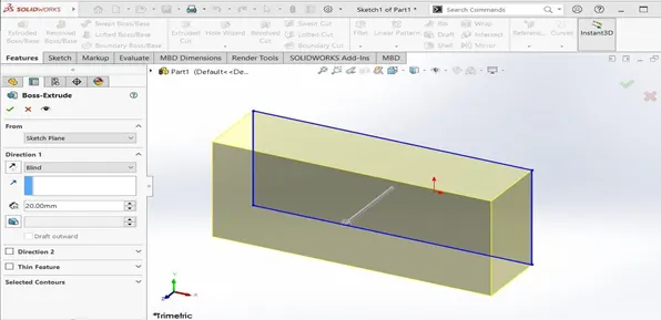
EXTRUDE BOSS
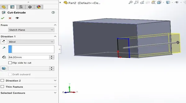
EXTRUDE CUT
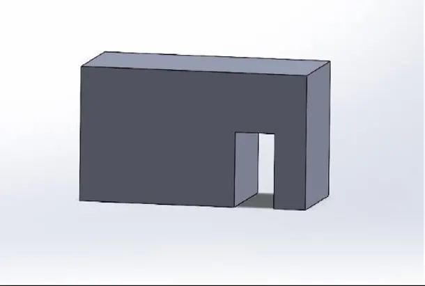
AFTER EXTRUDE CUT
REVOLVE: It is used to revolve a 2D sketch along an choose axis and makes it a 3D model. To create a revolve create a new sketch and create all solid sketch geometry on one side. Choose revolve from the features and pick the axis you want to use for the revolve. You can specify direction and angle also. Like extrude it is also of two types Revolve boss and Revolve cut. Revolve boss adds material by revolving one or more profiles around a centerline and revolve cut remove material. The revolve feature can be a solid, a thin feature, or a surface.
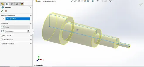
REVOLVE BOSS
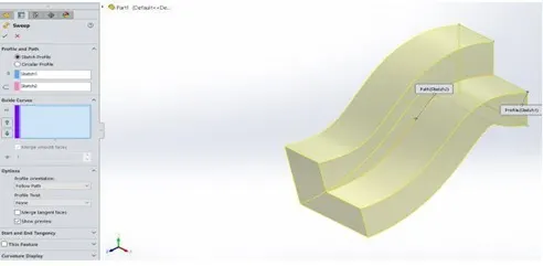
SWEEP: Sweep is the one feature in Solid works that helps sweep a closed profile along a closed or open path. It is used to make long pipe or tube-like structure. To create a sweep first sketch a closed, non-intersecting profile on a plane or a face. If we use guide curves then we have to create the path for the profile using a sketch, existing model edges, or curves.
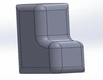
FILLET: Creates a rounded internal or external face on the part. You can fillet all edges of a face, selected sets of faces, selected edges, or edge loops. Radius are specified for the fillets.
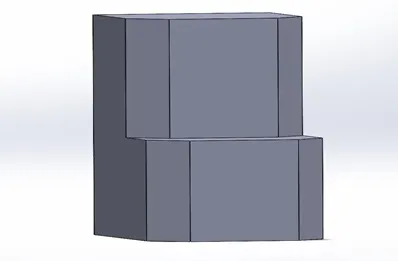
CHAMFER: A chamfer is the sloped or angled edges or corners of a part design. It is an antonym of the fillet. Instead of having a curved shape, a chamfer is straight and has a sharp angle. If your design requires sharp corners to be efficient for its purpose, you should choose chamfer over the fillet.
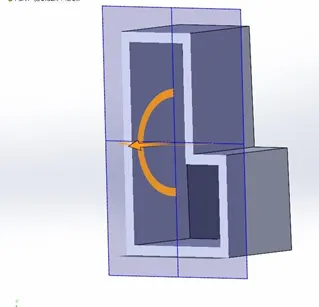
SHELL: The Shell command allows you to define a wall thickness and automatically hollow the part, while allowing faces to be removed as needed. If no faces are specified to be removed during a Shell feature, the part will be hollow, but this can only be seen by creating a cross section of the part.
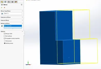
MIRROR: Mirroring is another way that SolidWorks can create a copy of an existing object. We must choose a plane to mirror parts. In most cases, we will have to create your own plane to have the mirror done.
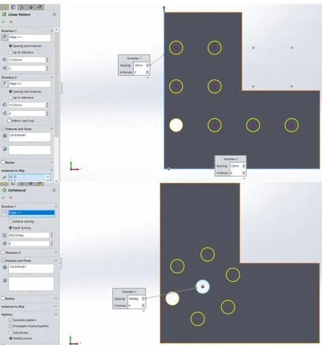
LINEAR AND CIRCULAR PATTERN: Pattern tool allows us to create patterns along a planar or 3D curve. The Linear Pattern Command is used to drive features, faces, or bodies in a linear direction. The Circular Pattern Command is an excellent tool used to replicate features, faces, or bodies in a rotational manner about an axis.
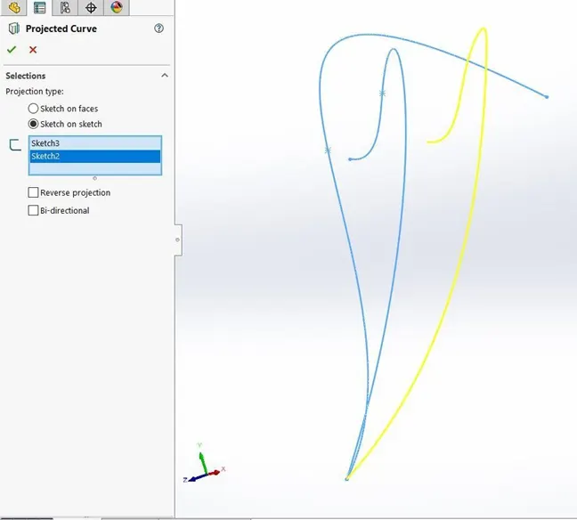
PROJECTED CURVE: To project existing curves onto planes or surfaces in a specified pierce direction. Laying down. To lay down existing curves onto a surface without changing the length and shape of the curves. The original curves and the curves laid down are matched by associating a point on the curve with a point on the surface.
MODELLING OF PARTS
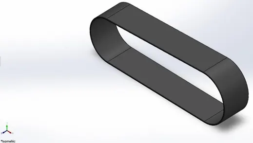
TRANSMISSION BELT: It was modelled by using basic tools like extrude and fillets then appearance was given to the transmission belt.
KICKSTAND: Kickstand helps to stand upright when not in use. A kickstand can rotate so that it can be flip up and down. The body of kickstand was created by using loft tool and dome was applied at the ends. Then split tool was used to create flat bottom end.
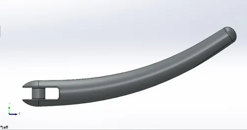
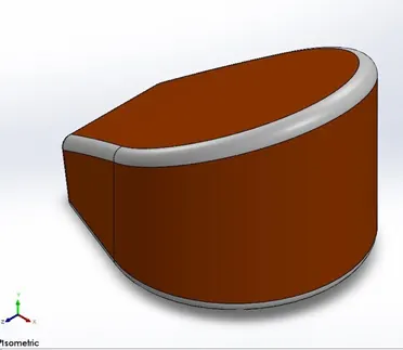
OIL TANK: The name itself suggest its function, Oil tank was modelled by using mirror and combine features. Shell feature was used to make it hollow after extrude.
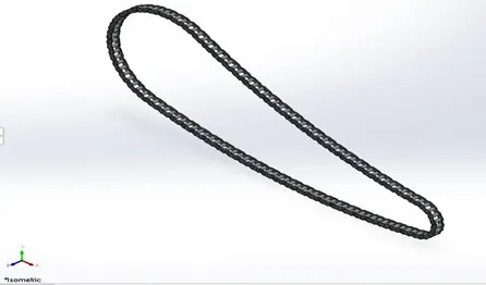
CHAIN: Chain drive is a way of transmitting mechanical power from one place to another. It is often used to convey power to the wheels of a vehicle, particularly bicycles and motorcycles. It is also used in a wide variety of machines besides vehicles. First the chain blocks are made then we created the chain curve driven pattern and the mirroring at the end. curve driven pattern has to be done multiple time for proper fitting of inner and outer link.
FRONT AND REAR FENDER: Fender are part which basically surround the wheel to prevent the dirt and sand being thrown into air due spinning of wheel. The main command used was revolve feature.
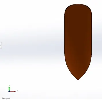
FRONT FENDER
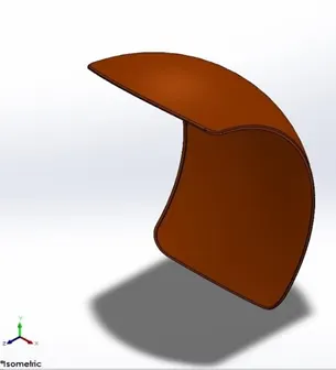
REAR FENDER
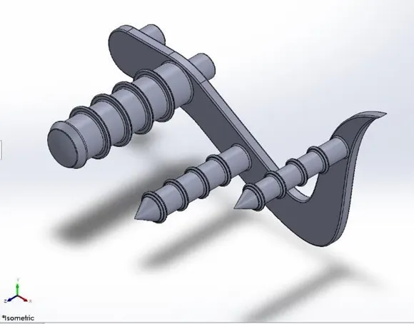
PEDAL: A pedal is a used to rest the foot of rider. Many commands like Splines, fillets, dome and linear pattern are used to model the pedal.
FRONT AND REAR WHEEL: Firstly, we all know the uses of wheel, to create wheel first the rim is designed using revolve feature and then spider webbed spokes are created by using extrude cut, then rotor and caliper are designed, then the threads of wheel is created by using extrude cut and patterning them all over the wheel. Dimension of front and rear wheel is different and rear wheel has sprocket for chain.
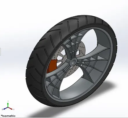
FRONT WHEEL
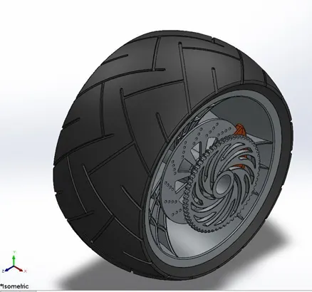
REAR WHEEL
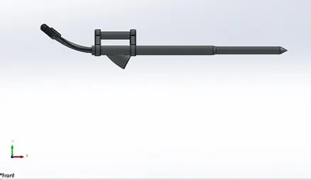
FRONT FORK: A front fork connects front wheel and axle to its frame, it also contains front light of the chopper, the modelling of part used command like revolve, mirror and sometimes we have to create plane for sketch and projected curve was used.
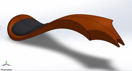
GAS TANK: The gas tank covers the oil tank and engine. The seat and opening for fuel tank are located on the top of gas tank. One half of the tank was created and the next half is created by mirroring the next half. Then seat was modelled on the top of it and fillets were applied. Shell command was used to make the tank hollow.
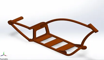
CHASSIS: A motorcycle's chassis or frame forms its skeleton. All the components of a motorcycle, like the suspension, wheels, fuel tank, seats, handlebars etc., are attached to this base structure which lends a motorcycle its strength and ability to handle well. It involved features like splines, projected curves and split.
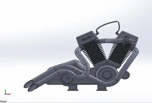
ENGINE: Motorcycle engines work the same way that car engines do. They consist of pistons, a cylinder block and a head, which contains the valve train. The pistons move up and down in the cylinder block, driven by explosions of a fuel-air mixture that has been ignited by a spark.
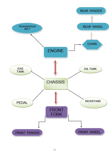
ASSEMBLEY CHART
ASSEMBLY OF AMERICAN CHOPPER
For the assembly, first we have to know about mates. Mate operation is the basic tool for assembling the parts. There is various mate operation like coincident, parallel, perpendicular, tangent, concentric, angle mates and many more. For assembly we have taken chassis as the reference. We have fixed different parts by making chassis as the reference and by applying different mates we have assembled the chopper.
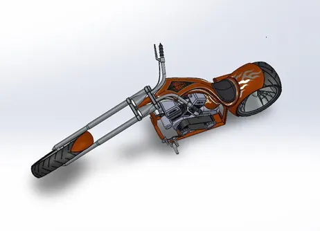
AMERICAN CHOPPER ISOMETRIC VIEW
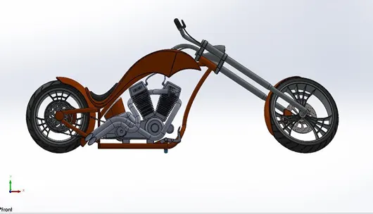
AMERICAN CHOPPER FRONT VIEW
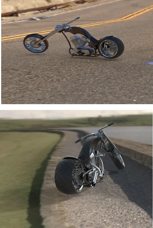
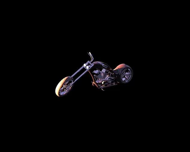
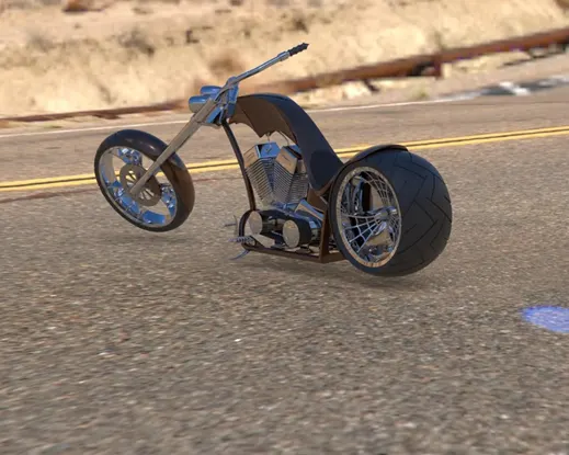
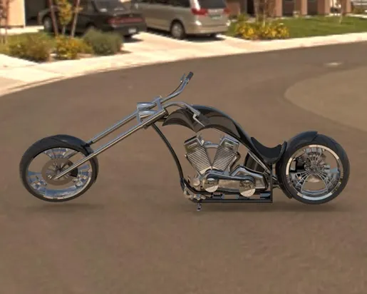
RENDERING OF THE CHOPPER
After assembly rendering is done to make design more realistic and natural with the environment. We have added decals, lights and cameras, set up the scene to make it look more presentable.