Week 8 - Challenge 3 - Switch Bezel Design
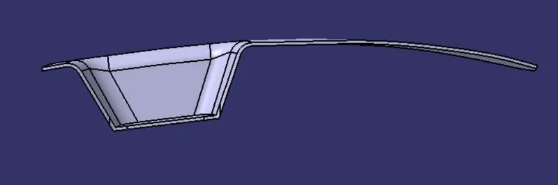
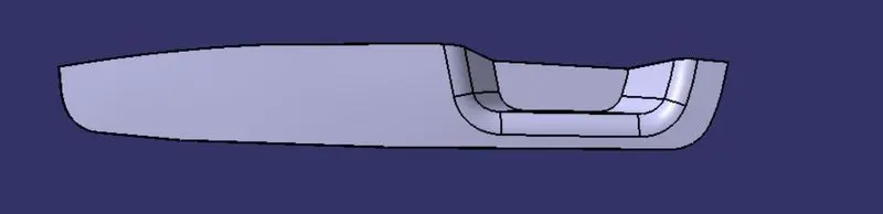
DESIGNING OF BEZEL SWITCH
OBJECTIVE
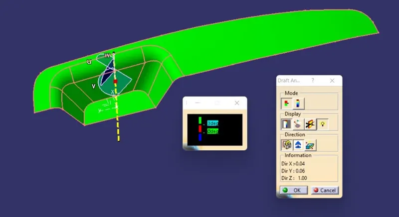
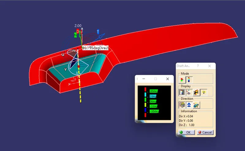
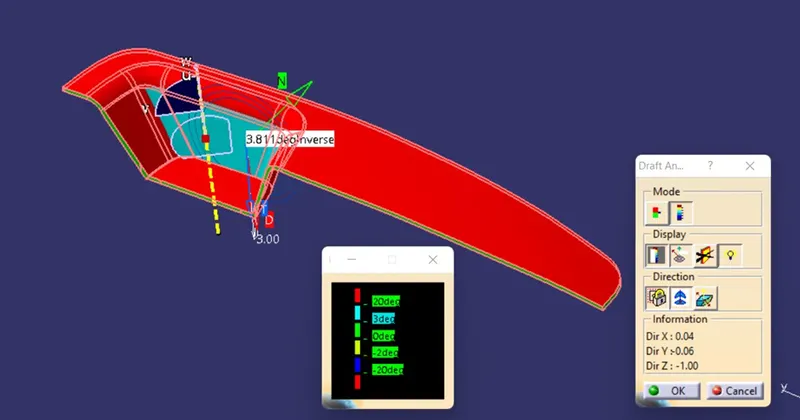
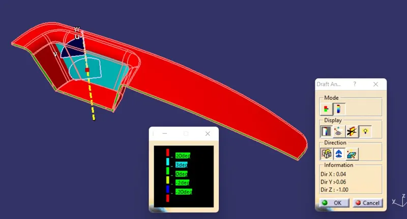
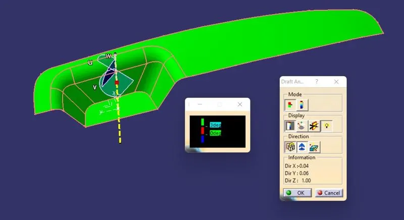
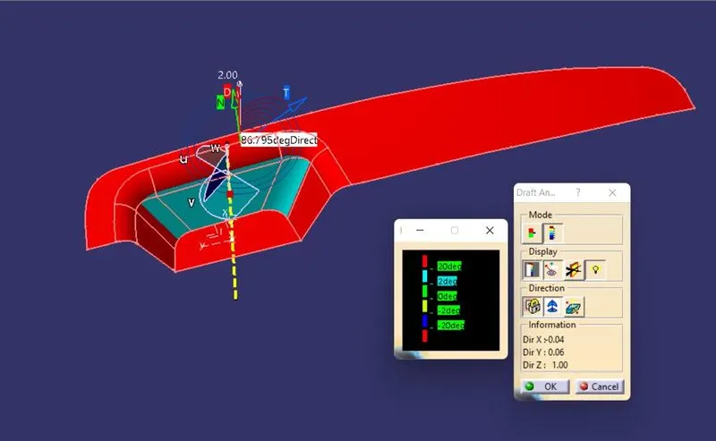
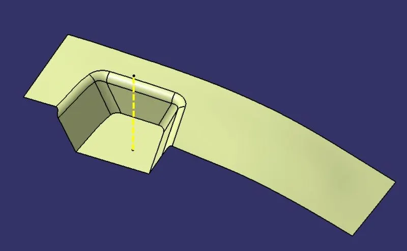
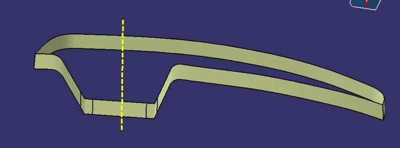
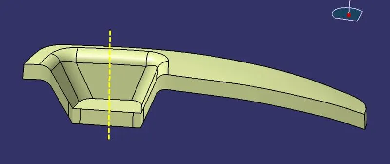
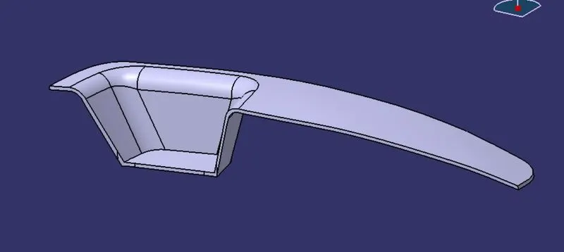
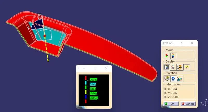
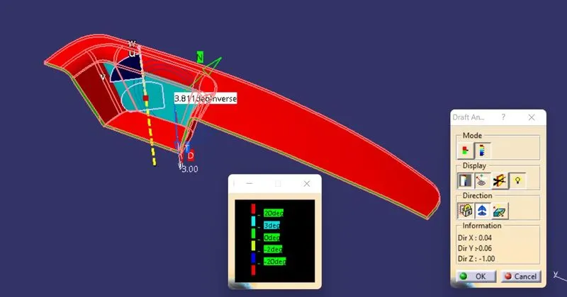
The objective of the project is to design the Switch Bezel and to do a draft analysis for it by creating the required tooling axis.
INTRODUCTION
The switch bezel is the part of a door which holds the switches. Moulding is the method used to manufacture it.
STEPS FOR DESIGNING THE SWITCH BEZEL
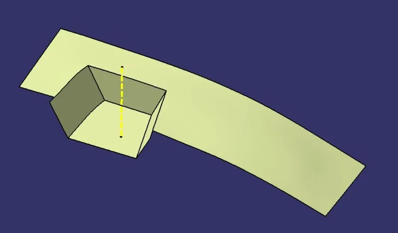
First, we have been given CLASS A surface, from that we have to create CLASS- B and CLASS-C surface.
Before creating CLASS-B SURFACE we have to create tooling axis.
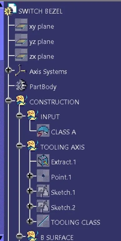
CREATION OF TOOLING AXIS
Taking into the consideration the ejection from the cavity the mould after manufacturing the switch bezel have the nominal 3-degree draft angle. We have created the tooling axis considering that.
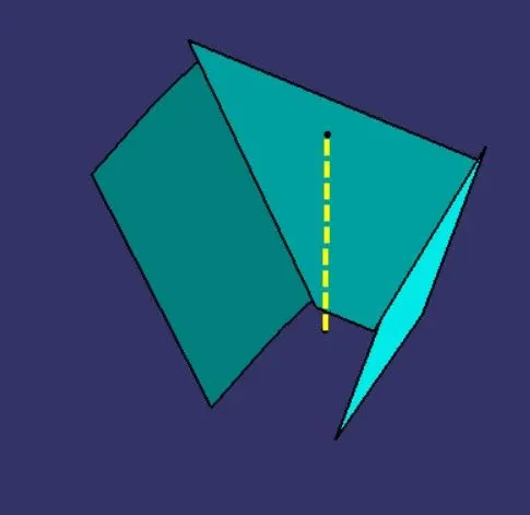
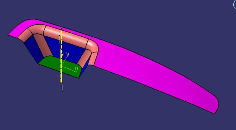
First the base surface of the class A was extracted and a point was created at the centre of it and an axis system was created at that point.
Then an intersection is created along the YZ plane and the two lines are created the along the direction of faces which are doubtful or which may cause problem during the ejection.
Then a bisecting line is created with the help of those two lines, and that is are tooling clearing along Y direction.
Now the same method is along the X direction to create the Tooling clearing along X axis.
After that a bisecting line is created using the tooling clearing along the X and Y direction, and that is our TOOLING AXIS.
CREATION OF CLASS B SURFACE
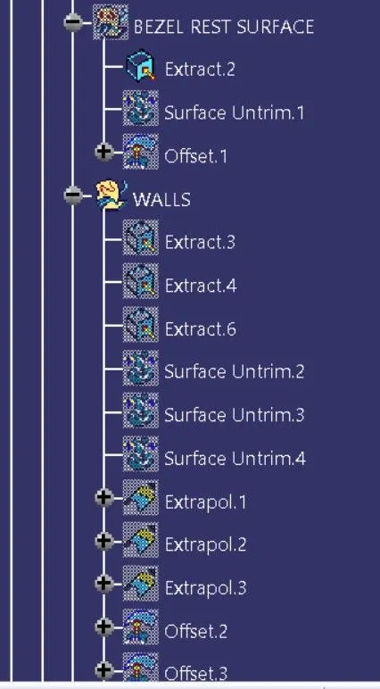
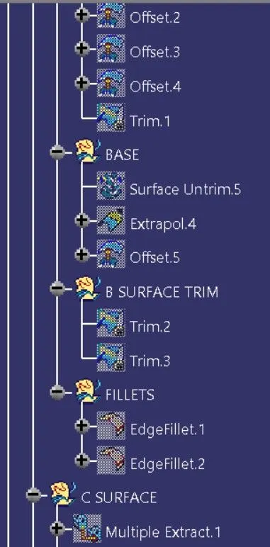
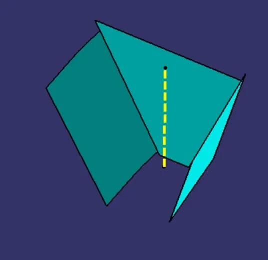
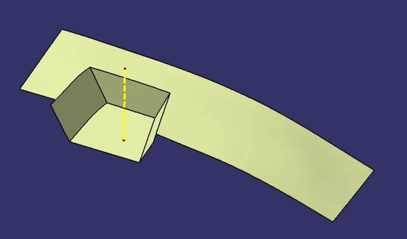
To create it the required surface must be extracted and then untrimmed all the extracted surface.
Then all the untrimmed surface must be extrapolated to get the intersection between them.
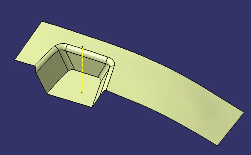
Since the Switch Bezel is 2.5 mm thick, so all the extrapolated surface must be offset by 2.5 mm
Then the trim operation must be carried out to achieve the required surface.
Finally, all the fillets are done.
CREATION OF CLASS C SURFACE
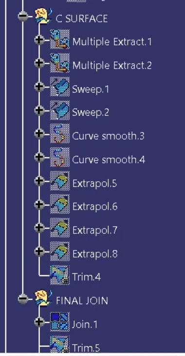
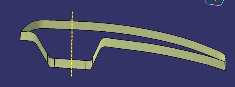
First required outer edges of class A surface were extracted using multiple extract.
Then by using sweep command the surface was created with the following feature control
Profile type- line
Subtype- with draft direction
Guide curve – boundary created
Draft direction – tooling axis
Angle- 3-degree
Length- 20mm.
CREATION OF CLOSED SURFACE
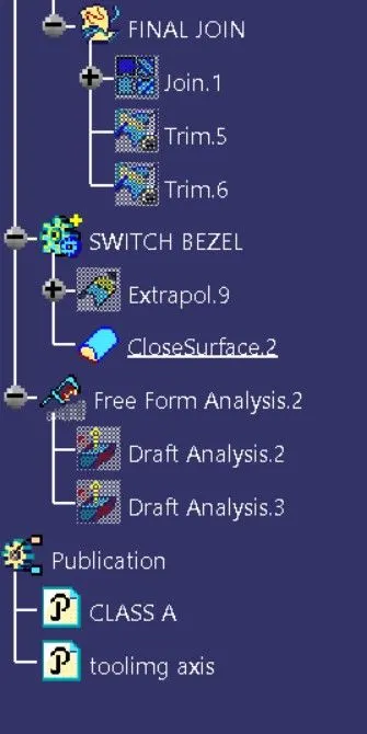
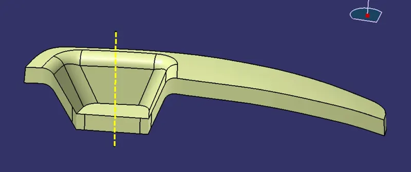
Now the class A surface and class C surface were joined together.
After that the join surface and the class B surface are trimmed together to form a closed surface.
Then by defining the part body by using the closed surface command in Part Design ,the solid body is created.
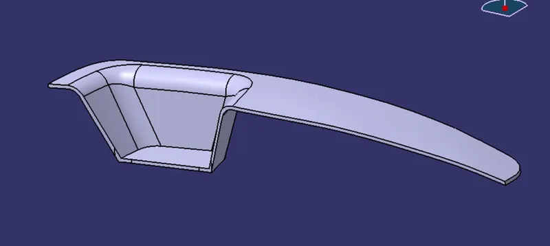
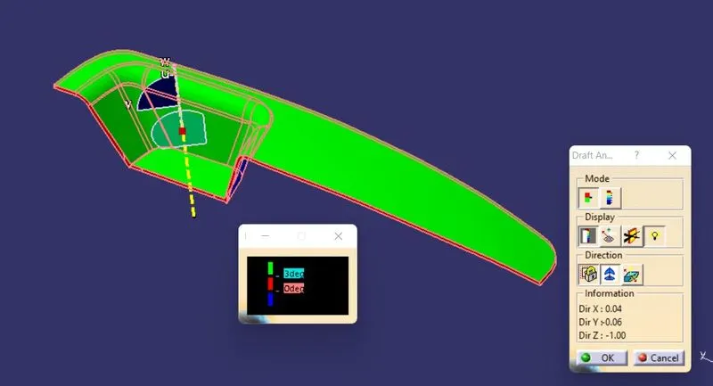
DRAFT ANALYSIS
The class A surface is checked before creating the class -B and C surface and finally the solid body must be analysed.