Radar Mast & Final Assembly of Yacht
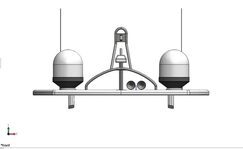
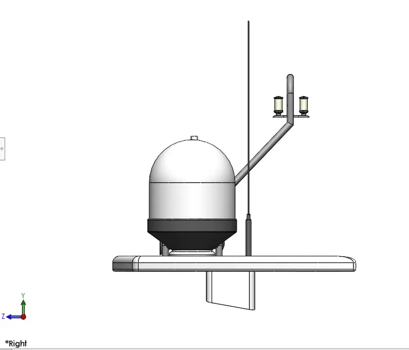
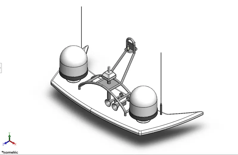
Radar mast
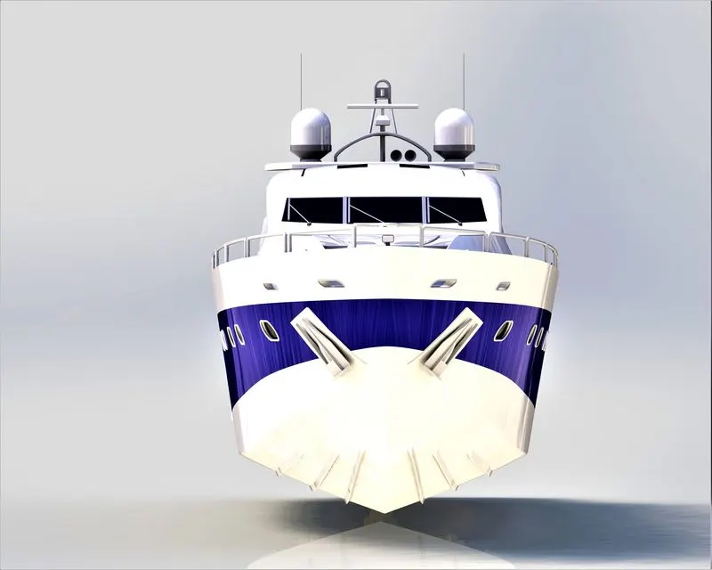
front view
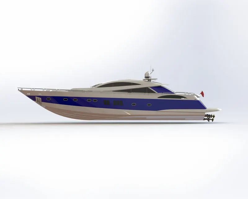
right
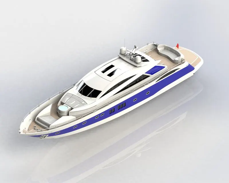
isometric
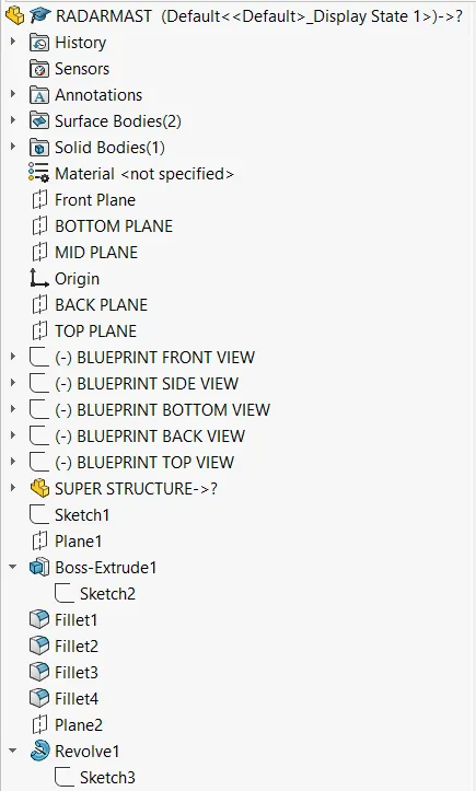
tree history
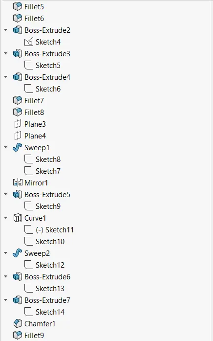
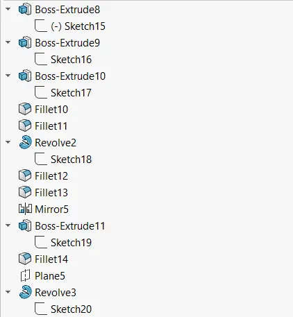
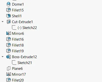
DESIGN AND MODELLING OF AMERICAN PREDATOR YACHT
Aim: To design and modeling of American predator Yacht by using Solidworks and visualize.
Objective:
- The main theme of this is to design and modeling of Yacht by using Solidworks and visualization software’s.
- To assemble the different part model of the Yacht
- To create a photorealistic rendering of the Yacht by using Solidworks visualization.
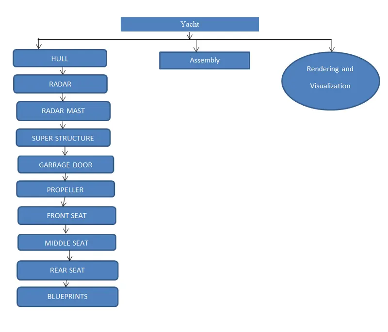
Flow chart of the Yacht:
Introduction about features used in this project:
- Sketch: It is the two dimensional representation of the model with respect to the plane from the outside of the model. The following entities are line, arc, spline, rectangle, and circle.
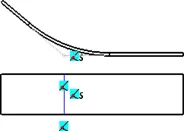
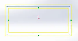
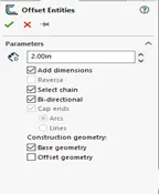
- Offset: offset one or more sketch entities, selected mode edges or model faces by a specific distance.
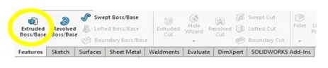
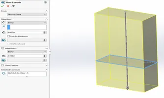
- Boss/Base extrudes: Extrude is a type of feature available in solidworks to convert 2D-sketches into 3D-models.
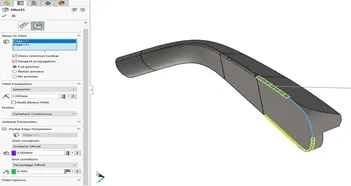
- Fillet: It is to create the rounded internal and external faces on the part you can fillet all edges of a faces, 2selected sets of faces selected edges or edges loop.
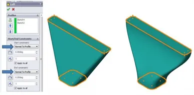
- Loft: The loft is to generate complex geometry in single features. It does these by interpolating surfaces between various cross-sections of a model.
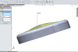
- Dome: Select one or more planes or non-planar faces. You can apply domes to faces whose centroid lies outside the faces.
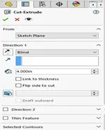
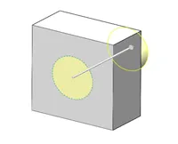
- Extrude cut: It is another feature which helps to remove materials from the 3D model. It is just opposite to extrude Boss/Base features.
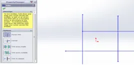
- Trim entities: This is the feature to remove unwanted lines. The trim types are available in 2D-sketch and 2D-sketch in 3D plane.

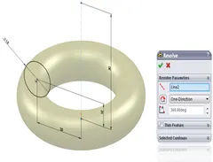
- Revolve extrude: Create a sketch that contains one or more profiles and a centerline, line, or edge, to use as the axis around which the feature revolves.
- Shell: The shell is used to the thickness of thin and thick shell elements.
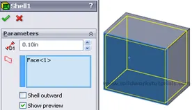
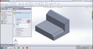
- Chamfer: A cut on the edge or corner of something that makes it slope slightly rather than being perfectly square.
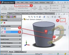
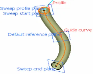
- Sweep: The sweep can used to create a shape by moving a 2D sketch profile along a 2D or 3D sketch path.
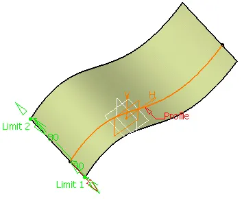
- Surface extrudes: It is used to extrude the surface at certain values to produce a shape.
- Surface revolve: It is used to revolve surface at reference axis or lines in the surface form.
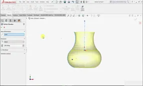
- Swept surface: It provides surface by closed profile along a closed and open surface.
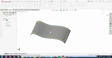
- Offset surface: It is used to produce reference line of surface to produce another surface.
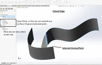
- Extend surface: It is used to extend the surface of the part.
- Filled surface: It is used to fill the blank surfaces.
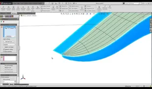
- Ruled surface: The set of points swept by a moving straight line.
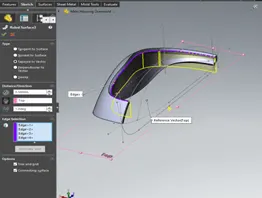
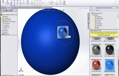
- Appearances: It is used to apply the colors of metals, paints etc.
Part models of Yacht:
- Hull
- Super structure
- Blueprints
- Radar
- Radar mast
- Garage door
- Propeller
- Front, Middle and Rear seats
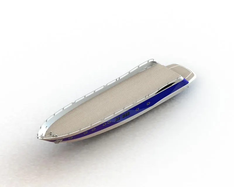
HULL:
It is the watertight enclosure of the ship, which protects the goods carrying area, machinery, and accommodation spaces of the ship from the weather, flooding, and structural damage.
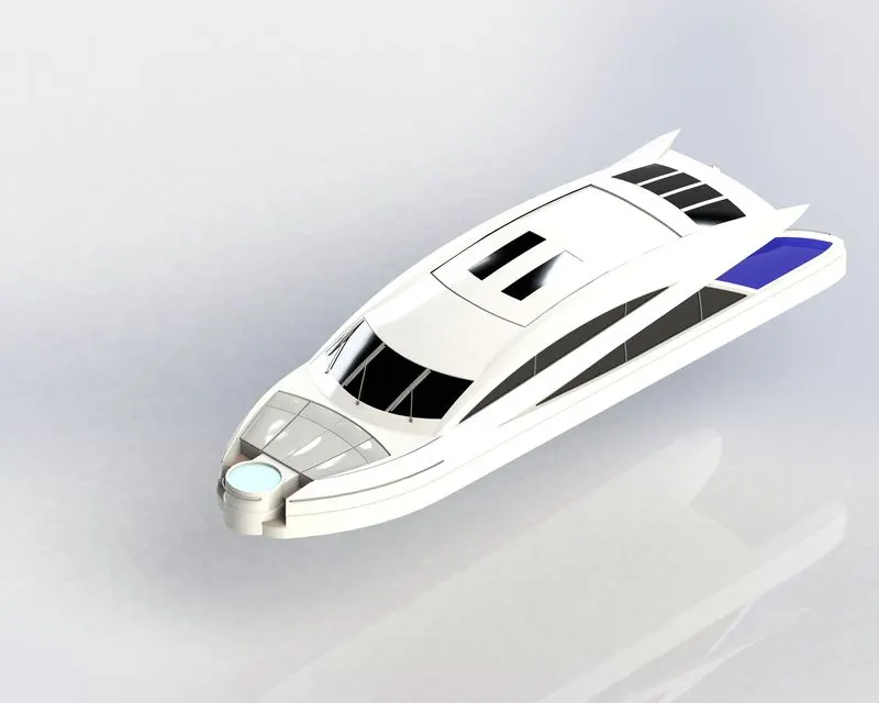
SUPER STRUCTURE:
A superstructure is an upward extension of the Yacht. It is like a head & gives a pretty good look and mounted over the hull. By the Base isolation whole yacht can be protected from severe damage.
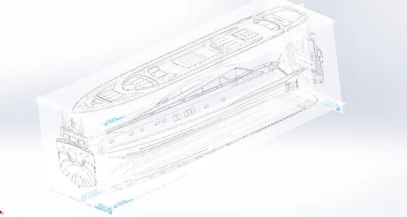
BLUEPRINTS:
It is the reference of the whole design of yacht by using the yacht we can model whole design of yacht.
RADAR:
It is used to go in proper route and signals of yacht to nearer signal receiver and relative to the proper position of yacht.
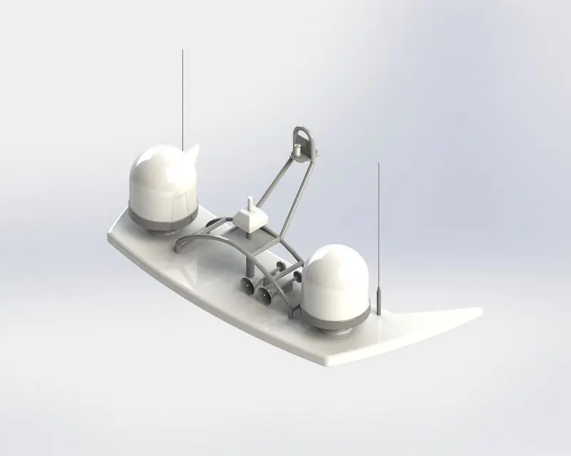
RADAR MAST:
It is complete assembly of radar to receive signals from the emitter to go in route.
GARAGE DOOR:
It protects from bad weather where things are stored in garage.
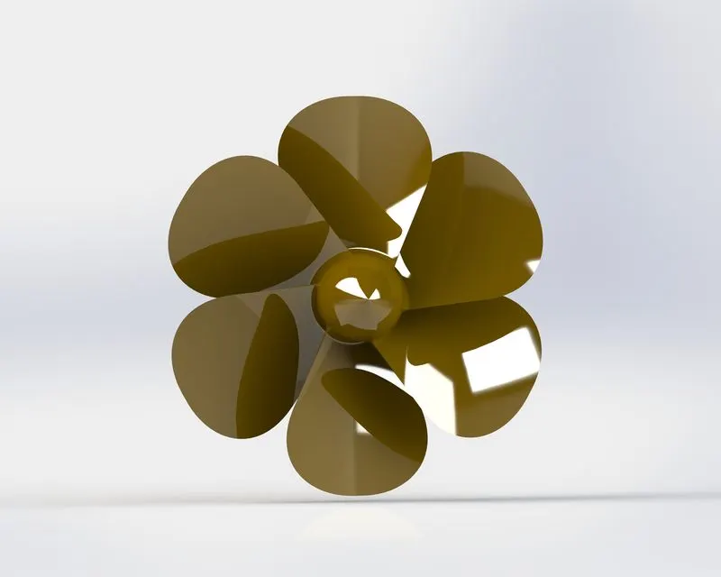
PROPELLER:
Its rotary motion through the air creates a difference in pressure between the front and back surfaces of its blades. It provides thrust so that the yacht moves easily.
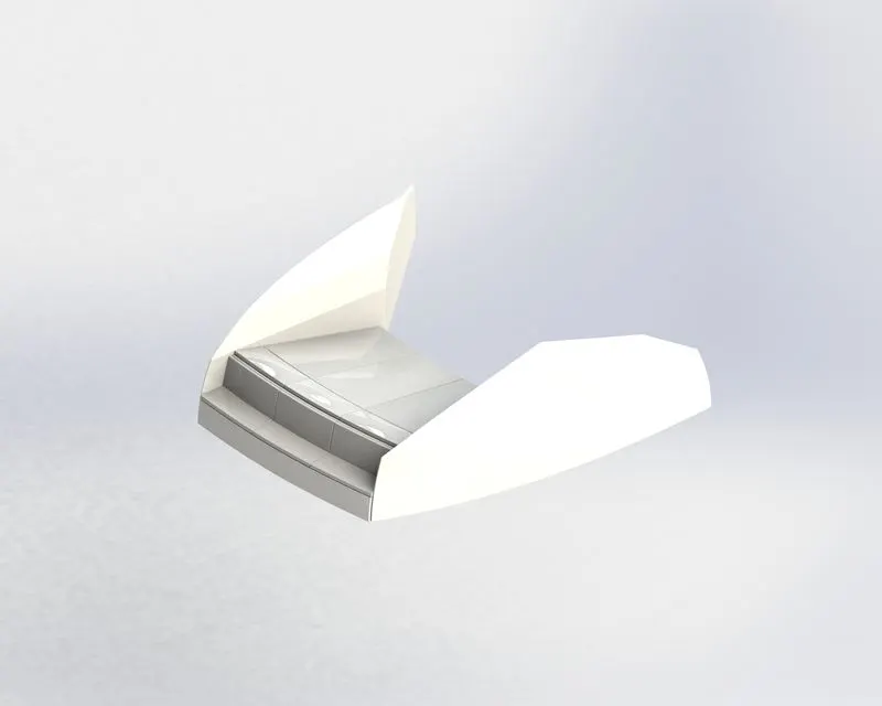
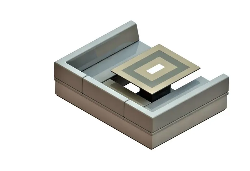
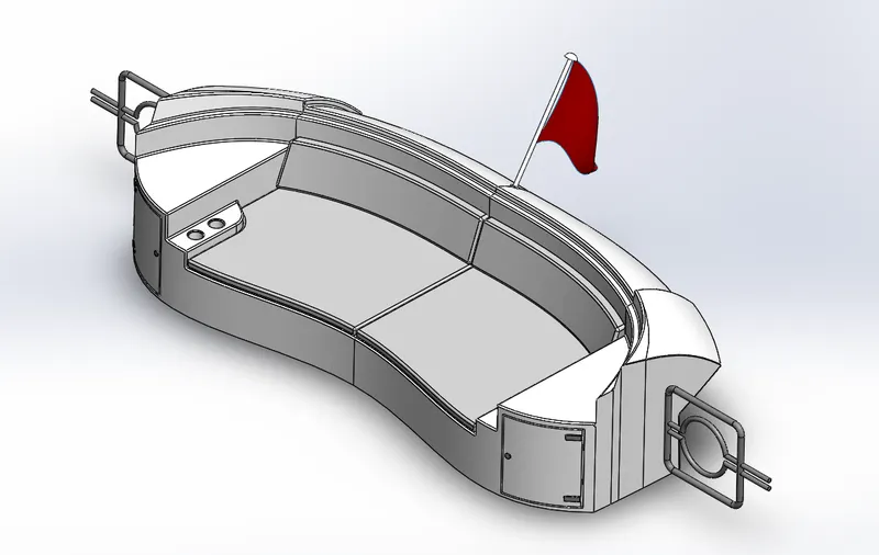
FRONT, MIDDLE AND REAR SEATS:
It is used to take rest in the yacht. It’s an important part in yacht
ASSEMBLY OF AMERICAN PREDATOR YACHT
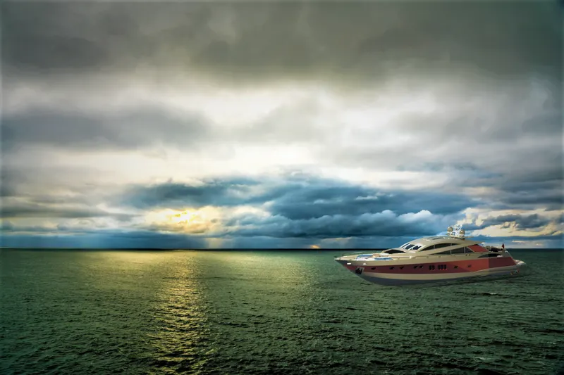
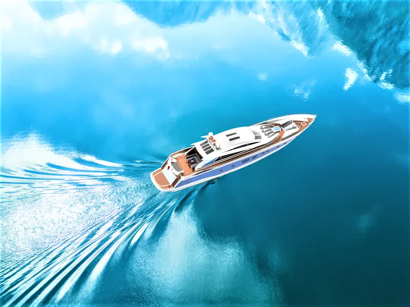
It is a very important part because of different materials, colors, etc. to be applied to assembly. Here, the product to be seen under environmental conditions with different views. It gives a realistic view of the model relative to the environment.
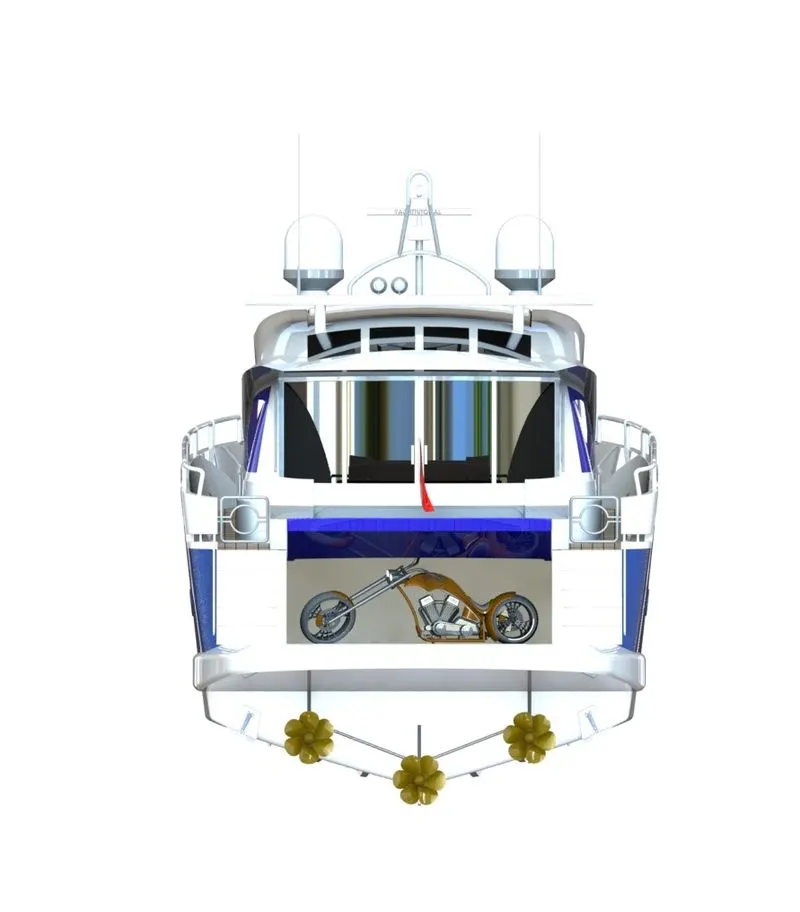
RENDERING AND VISUALIZATION
Rendering and visualization is the final realistic and graphical process that can be done by using with the Photoview360 mode and visualization modes. By this we can done the process.
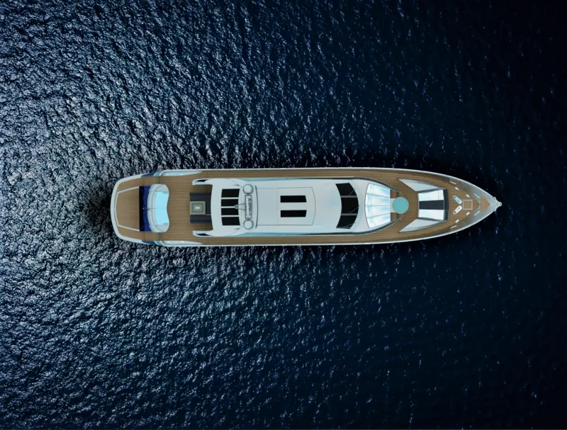
The environments background scenes, lightings, sunlight, focus lights, shadows etc. are shown in the rendering process. Visualization is done in the Solidworks visualize software.
Middle of the Ocean
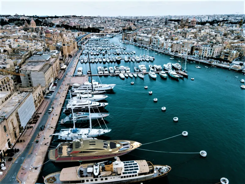
Dock yard stands:
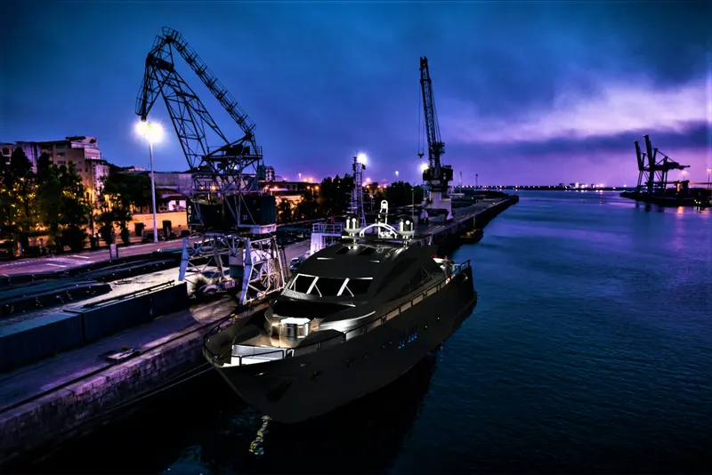
Night vision of yacht:
Light sunny in ocean:
Water splash in ocean by Yacht:
CONCLUSION:
- The all part models are completely modeled.
- The all part models are should be assembled and mates and constraints are successfully applied.
- Rendering and Visualization was done in the solidworks visualization and photoview360.