Photo Realistic Rendering
DESIGN AND MODELLING OF AMERICAN CHOPPER BIKE
Aim: To design and modeling of American chopper bike by using Solidworks and visualize the design by using Solidworks visualization.
Objective:
- The main theme of this is to design and modeling of American chopper bike by using Solidworks and visualization software’s.
- To assemble the different part model of the chopper.
- To create a photorealistic rendering of the chopper by using Solidworks visualization.
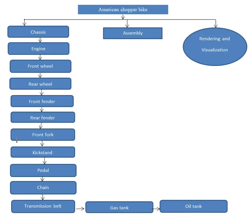
Flow chart of the Chopper:
Introduction about features used in this project:
- Sketch: It is the two dimensional representation of the model with respect to the plane from the outside of the model. The following entities are line, arc, spline, rectangle, and circle.
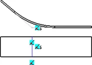
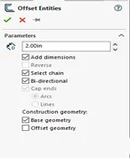
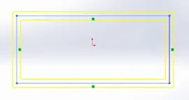
- Offset: offset one or more sketch entities, selected mode edges or model faces by a specific distance.
- Boss/Base extrudes: Extrude is a type of feature available in solidworks to convert 2D-sketches into 3D-models.

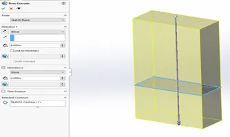
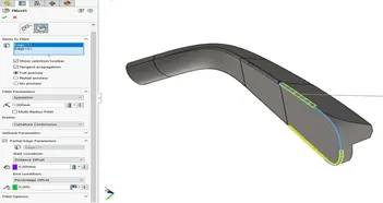
- Fillet: It is to create the rounded internal and external faces on the part you can fillet all edges of a faces, 2selected sets of faces selected edges or edges loop.
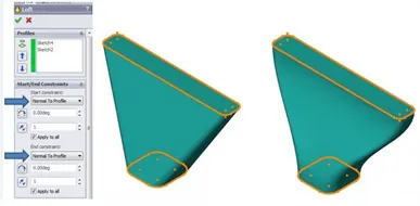
- Loft: The loft is to generate complex geometry in single features. It does these by interpolating surfaces between various cross-sections of a model.
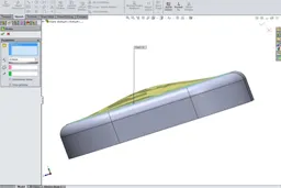
- Dome: Select one or more planes or non-planar faces. You can apply domes to faces whose centroid lies outside the faces.
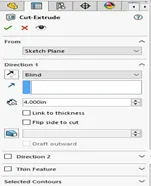
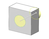
- Extrude cut: It is another feature which helps to remove materials from the 3D model. It is just opposite to extrude Boss/Base features.
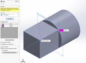
- Split: The split tool is used to project an entity into other surfaces or curved/plane faces you are also able to split faces on multiple bodies with on command.
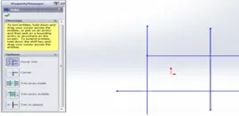
- Trim entities: This is the feature to remove unwanted lines. The trim types are available in 2D-sketch and 2D-sketch in 3D plane.

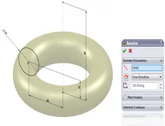
- Revolve extrude: Create a sketch that contains one or more profiles and a centerline, line, or edge, to use as the axis around which the feature revolves.
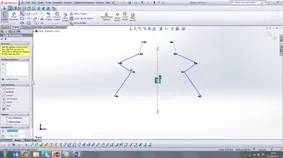
- Dynamic mirror: It is an important tool in solidworks. As you sketch the entities, they are mirrored about the pre-selected sketch entity.
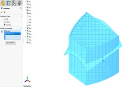
- Combine: Combine is the type of feature available in solidworks to manually combine the two bodies.
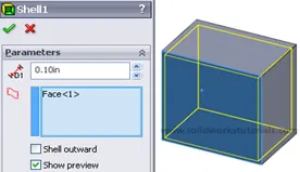
- Shell: The shell is used to the thickness of thin and thick shell elements.
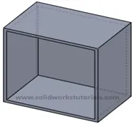
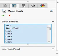
- Blocks: You can make, save, edit, and insert blocks for drawing items and sketch entities that you use often, such as standard notes, title blocks, label positions, and so on. You can attach blocks to geometry or to drawing views, and you can insert them into sheet formats.
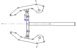
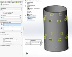
- Curve driven pattern: The curve driven pattern tool allows you to create patterns along a planar or 3D curve. You can base the pattern on an open curve, or on a closed curve, such as a circle. In the chain curve driven pattern is used.
- Chamfer: A cut on the edge or corner of something that makes it slope slightly rather than being perfectly square.
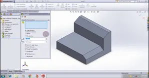
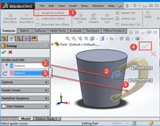
- Sweep: The sweep can used to create a shape by moving a 2D sketch profile along a 2D or 3D sketch path.
Part models of chopper bike:
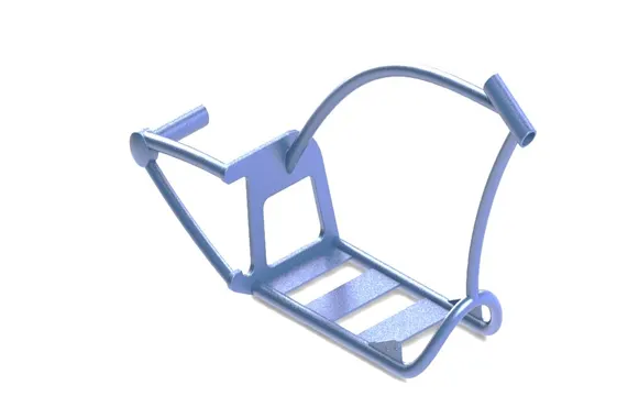
- Chassis:
It is the frame of the motorcycle to carry the whole parts like engine, gas tank, oil tank, kickstand, pedal and remaining all components.
The features is used in this is sketch, extrude, sweep, projecting curves, creating planes, appearance’s etc. these all are display in the figure.
- Engine:
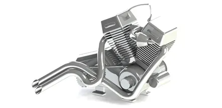
It is a component to run the vehicle and contains two V-shaped cylinder with four stroke engine. In the engine the chemical energy is converted in to the heat energy and then to the mechanical motion. By help of gear box and clutch the energy is passed through the chain to the wheel then vehicle is moved this is the operation of the engine.
The feature are used in the engine are sketch, boss extrude, fillets, chamfers, trim entities, projection curves, extrude cut, sweep, appearance’s, convert entities etc. are in figure.
- Front wheel:
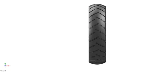
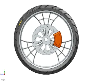
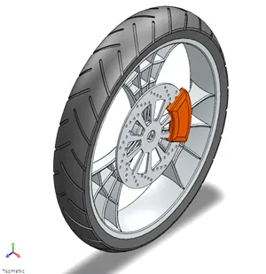
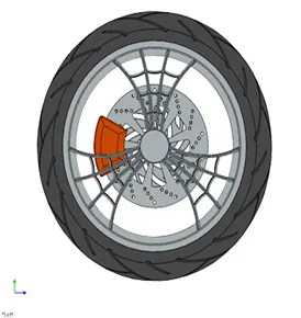
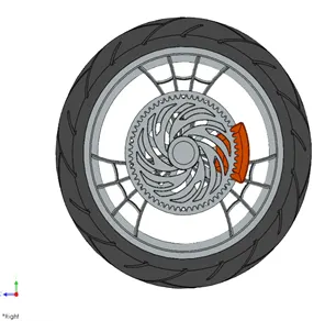
It is a circular part model produced by using steel and alloy materials.it contains rim, rotor, caliper, tyre. Top of the rim is covered with the tyre. The tyre is made up of rubber.
The feature are used in the wheel are sketch, boss extrude, revolve boss extrude, extrude cut, revolve cut, fillet entities, chamfers, linear pattern, circular pattern, appearances etc.
- Rear wheel:
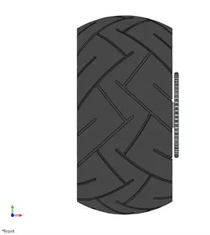
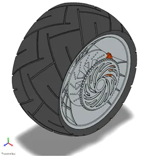
It is a circular component revolved with the axle and fixed below a vehicle to run easily on road.
Features are followed are sketch, revolve extrude, linear pattern, circular pattern, trim entities, fillet, chamfers, cut extrude, appearances, offset, revolve cut etc.
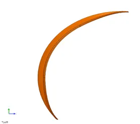
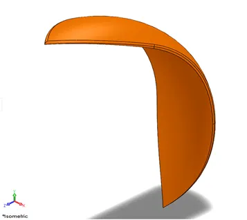
- Front fender:
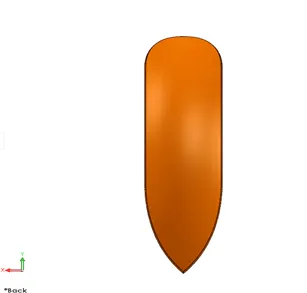
It is places on the front fork above the front wheel. It is used to stop the water and mud dust particle to protect the rider.
Feature’s are used are sketch revolve boss extrude, fillet entities, trim entities, dynamic mirror, split, shell, appearances etc.
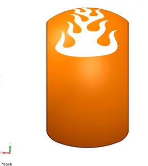
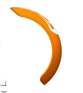
- Rear fender:
It is places on the rear axle above the rear wheel. It is used to stop the water and mud dust particle to protect the rider.
Features are used are sketch revolve boss extrude, fillet entities, trim entities, dynamic mirror, split, shell, appearances and decals etc.
- Front fork:
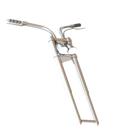
It is a component that used for suspension like telescopic and hydraulic is used for the bicycle or motorcycle forks. The forks can be mostly used for the hydraulic stock absorber with internal coil springs. They allow the front wheel from the imperfection’s on the road while isolating the rest of the motorcycle from the motion.
Features are used are sketch, boss extrude. Revolve boss extrude, revolve cut, extrude cut, fillet, dome, mirror, projection curves, reference curves, linear pattern, circular pattern, combine, appearances etc.
- Kickstand:
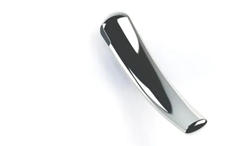
It is a metal rod and attached to the bottom of the chassis. It is also known as side stand and it is used to support the chopper is at rest position.
Feature are used are sketch, loft, dome, boss extrude, cut extrude, fillet, split, appearances etc.
- Pedal:
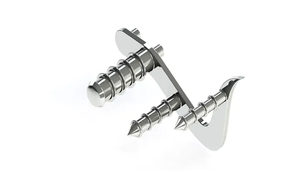
It is a component attached to the chassis. To put the legs of the rider while riding the bike comfortably.
Features are used are sketch, boss extrude, revolve extrude, chamfers, fillet, dome linear pattern, appearance’s etc.
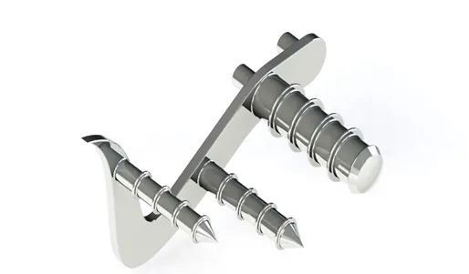
Pedal LHS
It is mirrored part of the pedal across the mid-plane
Features are mirror
- Chain:
Chain drive is a way of transmitting mechanical power from one place to another. It is often used to convey power to the wheels of a vehicle, particularly bicycles and motorcycles. It is made up of the metal.
Features are used are sketch, pattern, blocks, fillets, trim, extrude, appearance’s etc.

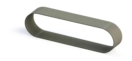
- Transmission belt drive:
A belt is a loop of flexible material used to link two or more rotating shafts mechanically, most often parallel. Belts may be used as a source of motion, to transmit power efficiently or to track relative movement. Belts are looped over pulleys and may have a twist between the pulleys, and the shafts need not be parallel.
Features are used are sketch, offset, extrude, fillet, appearances etc.
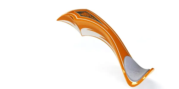
- Gas tank;
It is the storage tank of flammable fluids. It can store the gas and give to the engine when it required.
Features are used are 2D-sketch, sketch picture, fillet, shell, projection curves, surface extrude, surface trim, swept cut, surface knit, appearances and decals etc.
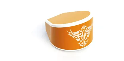
- Oil tank:
It is oil storage tank. It can store the oil and send that to the engine to run seamlessly.
Features are sketch, fillet, boss extrude, combine, shell, appearances and decals etc.
ASSEMBLY
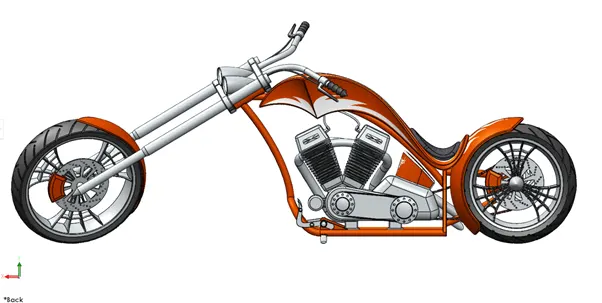
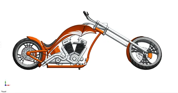
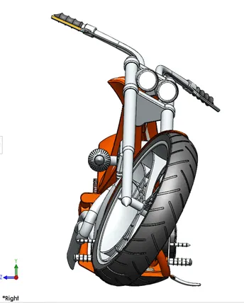
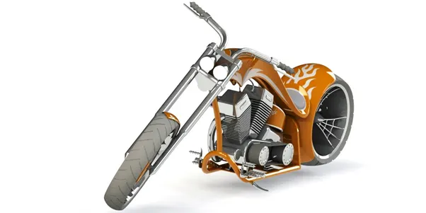
All the modeled parts are inserted one by one into the assembly. First we insert the chassis after that remaining parts are inserted to the chassis. Chassis is reference to the all part models. So that all the part models are move with respect to the chassis floats. For all part models should be attaches with the geometric mates.
Images of the assembly are displayed
RENDERING AND VISUALIZATION
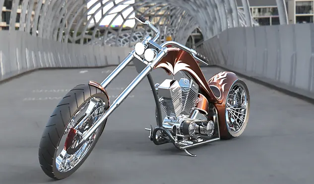
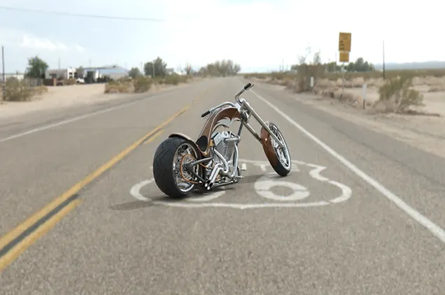
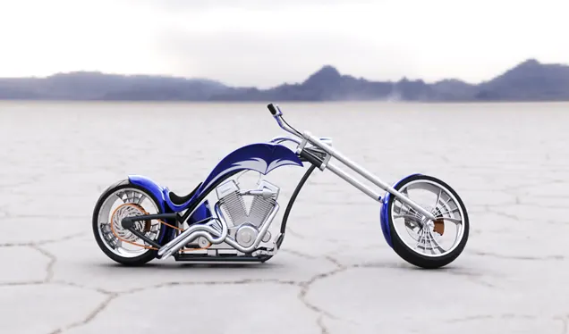
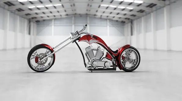
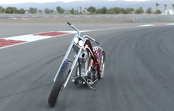
Rendering and visualization is the final realistic and graphical process that can be done by using with the Photoview360 mode and visualization modes. By this we can done the process.
The environments background scenes, lightings, sunlight, focus lights, shadows etc. are shown in the rendering process. Visualization is done in the Solidworks visualize software.
Downtown bridge:
Route 66:
Salt flasks:
Warehouse:.
Race track:
CONCLUSION:
- The all part models are completely modeled.
- The all part models are should be assembled and mates and constraints are successfully applied.
- Rendering and Visualization was done in the solidworks visualization and photoview360.