Radar Mast & Final Assembly of Yacht
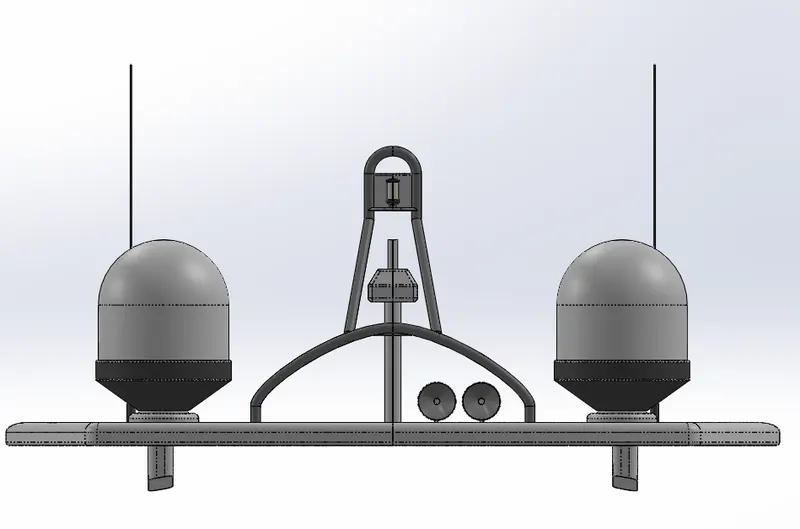
1. Radar Mast
Front View
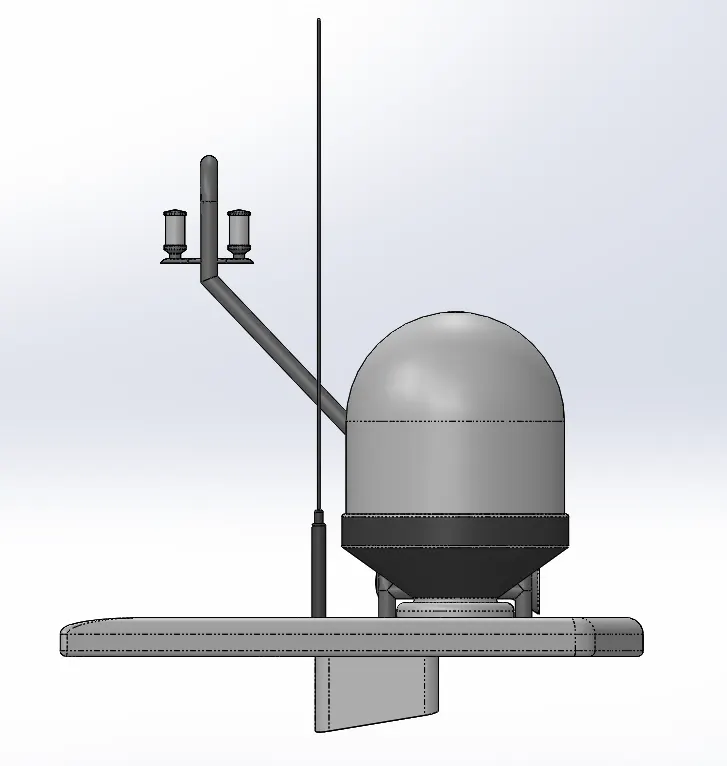
Side View
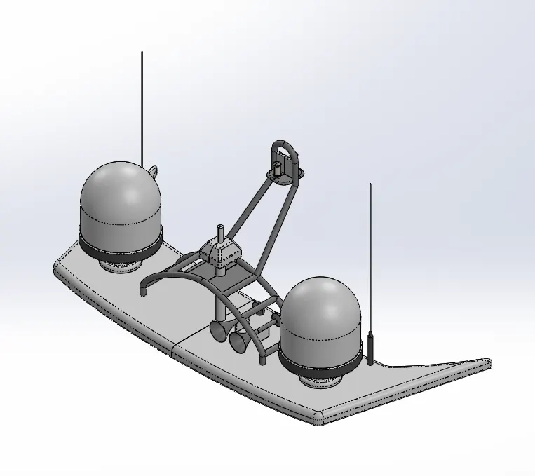
Isometric View
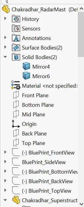
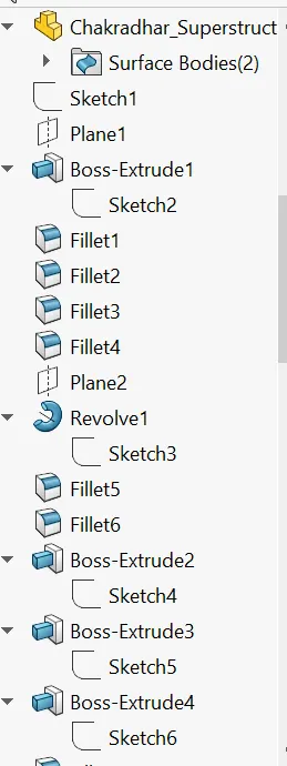
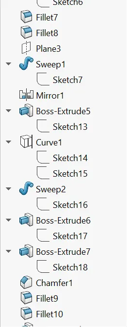
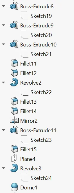
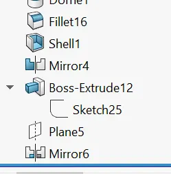
Feature Tree
Yacht Assembly
Design and Render of Yacht
1. AIM: To design a model of Yacht using Solidworks and Rendering by using Solidworks Visualize.
2. Objective:
- To design a Individual component of a Yacht by using Solidworks in Part mode.
- To design a Assembly by inserting all the components into the Solidworks Assembly and constraint them using available mates.
- To assign decals, lights, camera etc.
- By inserting this model into Solidworks Visualize and render the model with various environments.
3. Introduction:
Solidworks:
SolidWorks is a solid modeler, and utilizes a parametric feature-based approach which was initially developed by PTC (Creo/Pro-Engineer) to create models and assemblies. The software is written on Parasolid-kernel.
Building a model in SolidWorks usually starts with a 2D sketch (although 3D sketches are also available). The sketch consists of geometry such as points, lines, arcs, conics (except the hyperbola), and splines. Dimensions are added to the sketch to define the size and location of the geometry. Relations are used to define attributes such as tangency, parallelism, perpendicularity, and concentricity. The parametric nature of SolidWorks means that the dimensions and relations drive the geometry, not the other way around. The dimensions in the sketch can be controlled independently, or by relationships to other parameters inside or outside the sketch.
In an assembly, the analog to sketch relations are mates. Just as sketch relations define conditions such as tangency, parallelism, and concentricity with respect to sketch geometry, assembly mates define equivalent relations with respect to the individual parts or components, allowing the easy construction of assemblies. SolidWorks also includes additional advanced mating features such as gear and cam follower mates, which allow modeled gear assemblies to accurately reproduce the rotational movement of an actual gear train.
Finally, drawings can be created either from parts or assemblies. Views are automatically generated from the solid model, and notes, dimensions and tolerances can then be easily added to the drawing as needed. The drawing module includes most paper sizes and standards.
Solidworks Visualize:
Soliworks Visualize is a tool which helps in rendering the models. We have several options like Adding a Camera, Changing environment, Background, changing Appearances of the model.
4. Design Methodology:
FlowChart:
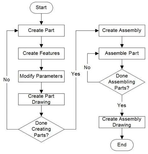
- We have created each individual part of this model in Soliworks.
- After finishing the all components, We started creating sub assemblies.After sub assemblies We created a final assembly.
- We insert all our components/sub-assemblies into the environment of SW assembly and constraint them using different Mates/Conditons available.
5. Description
- We will discuss each part individually and we will discuss the commands used in that part.
Propeller
Image of a Propeller Feature Tree
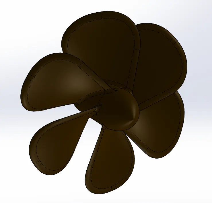
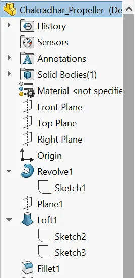
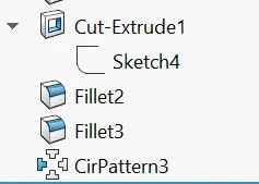
Features Used:
1.Sketch: To create a any part We have start with Skecth in a 2-D Plane.
The Sketch we have created by giving the proper dimensions is
- There are different options to create a Sketch by selecting the plane.[ Line,Circle,Spline,Rectangle,Arc,Ellipse,Slot,Fillet].
- To edit the sketch We have Trim Entities, Convert Entities,Offset Entities,Mirror entities, Linear,circular pattern etc.
- For Dimensioning We use Smart Dimension.
Note: Before closing the sketch ,The Sketch should be fully defined.
2.Revolve Boss:This feature is used to create a closed revolving body with respect to axis.
- Select the closed sketch that needs to be revolved.
- Select the axis of revolution by which the sketch will revolve.
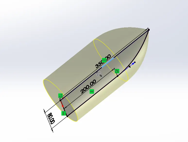
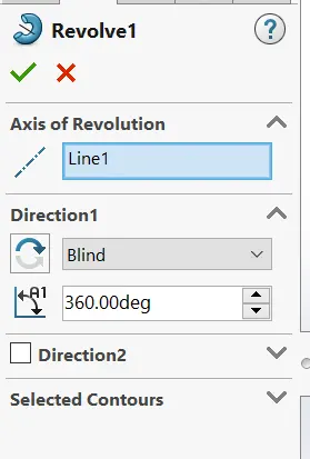
3.Plane: Here we Inserted a palne by using reference geometry. We can select a reference to create a new plane.
4.Loft Base: This feature creates a solid body between two closed profiles and wehave to give guide curves inorder to govern the profiles.
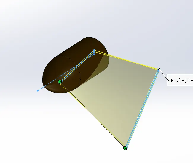
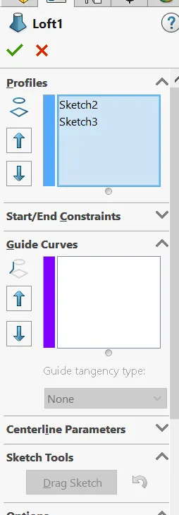
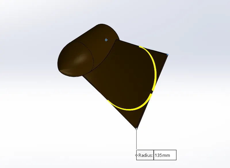
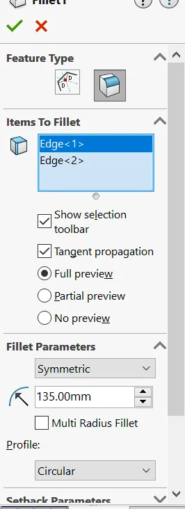
5.Fillet: This feature is used to convert Sharp corner to round edges.
In this Example we Creted a filet in differnts parts for example
- We have to select the edges to apply fillet.
- Assign the radius value for fillet.
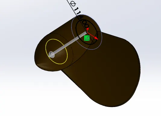
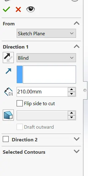
6.Extrude Cut: This helps removing the solid body from the solid body
- Select the type of extrusion and give distance values.
- You can also select the parts by using selected contours.
7.Circular Pattern: This feature helps in patterining the bodies/features/faces along the circle by giving certain distances.
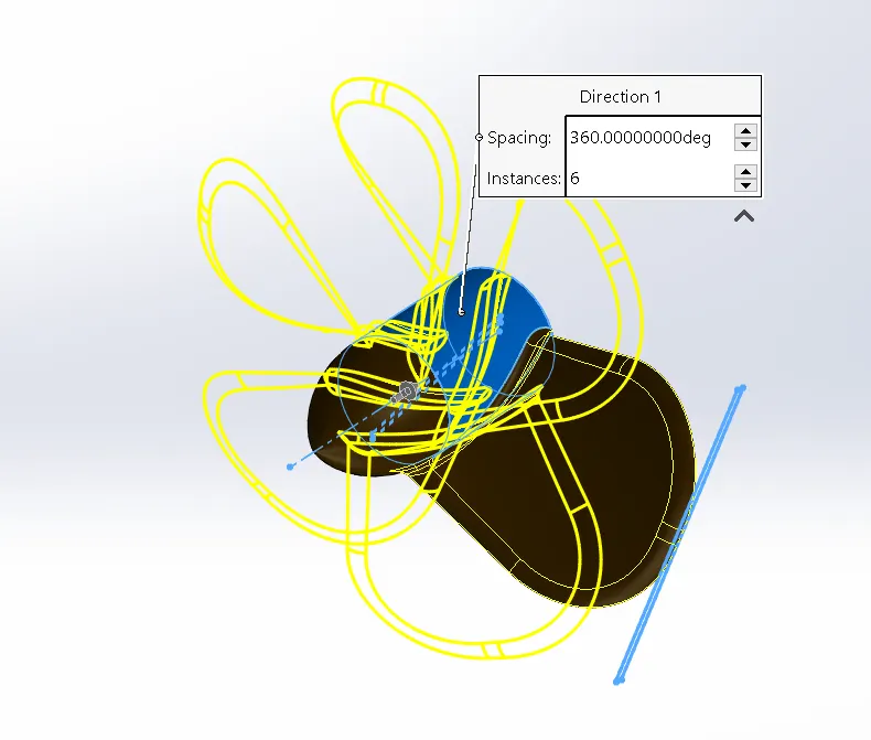
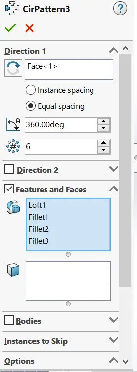
8.Appearance: Finally we added a Color to the part.
Radar
Image of Radar Feature Tree
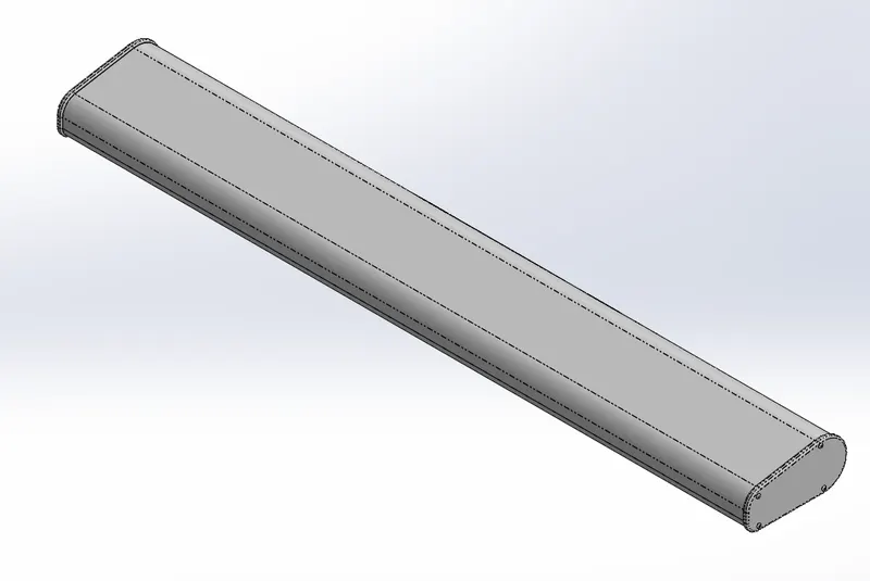
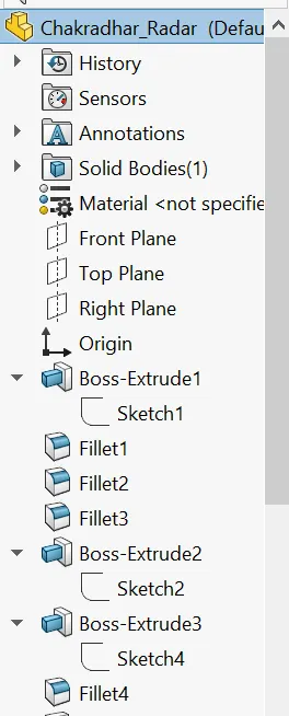
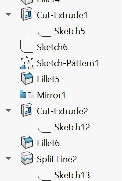
Features Used:
1.Sketch: To create a any part We have start with Skecth in a 2-D Plane.
2.Boss Extrude: This feature is used to Convert a closed 2D sketch into 3D Sketch.
We have another options to extrude the sketch [Up to vertex, Up to surface, offset, Midplane etc]
3.Extrude Cut: This helps removing the solid body from the solid body
- Select the type of extrusion and give distance values.
- You can also select the parts by using selected contours.
4.Sketch Pattern: This feature helps us to create a existing copy features and place them wherever you point in a sketch.
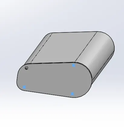
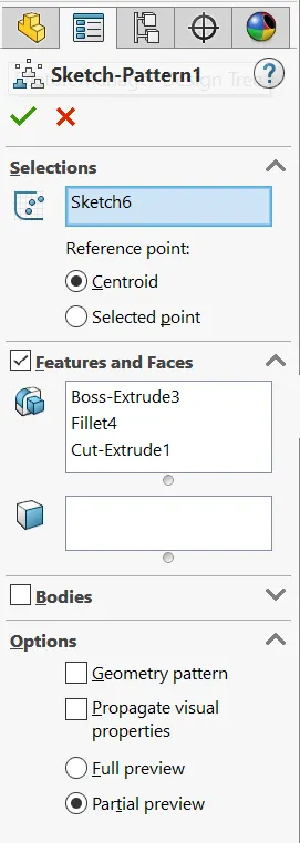
5.Fillet: This feature is used to convert Sharp corner to round edges.
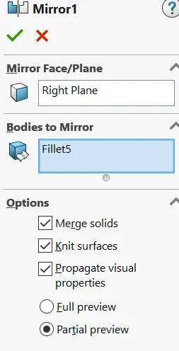
6.Mirror: This feature is used to mirror the parts with respect to the axis.
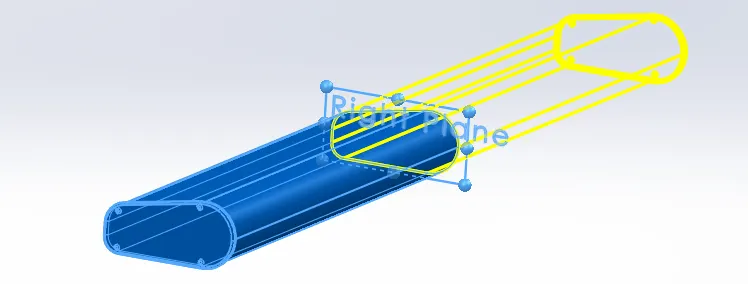
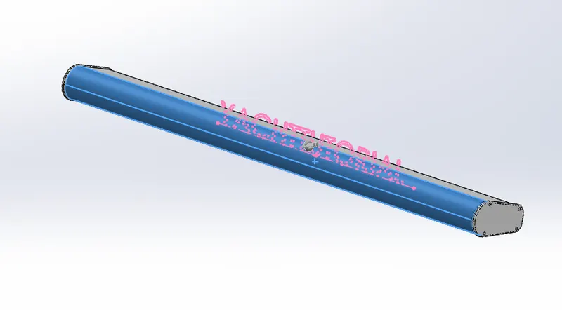
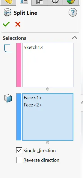
7.Split Line: This feature is used to project an entity on to the other surfaces
8.Appearance: Finally we added a Color to the part.
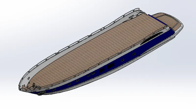
Hull
Image of a Hull
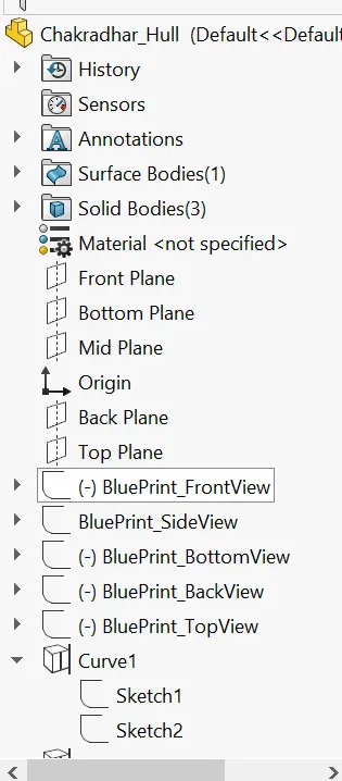
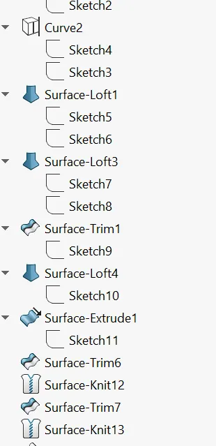
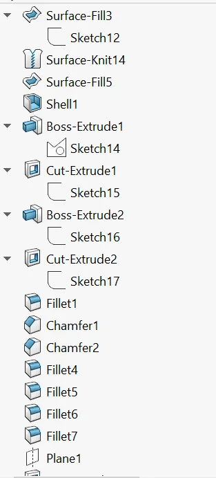
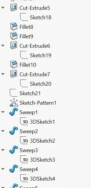
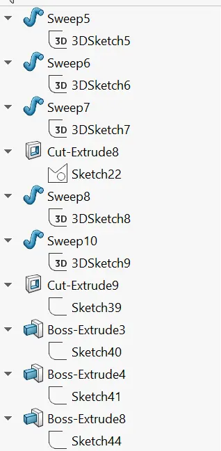
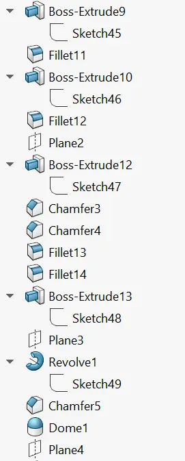
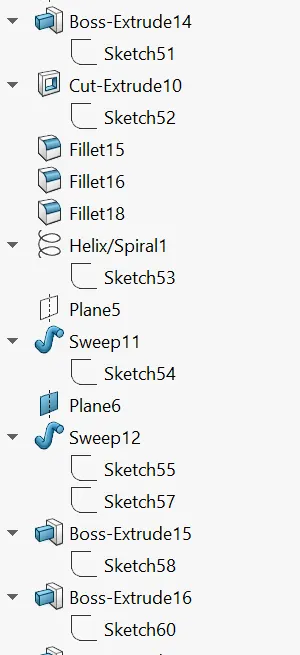
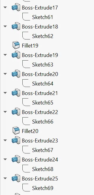
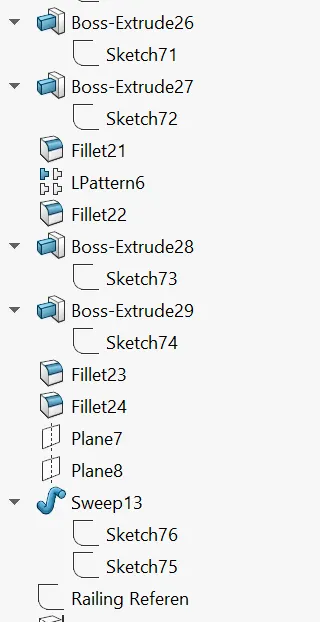
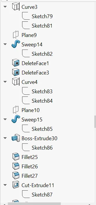
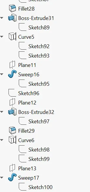
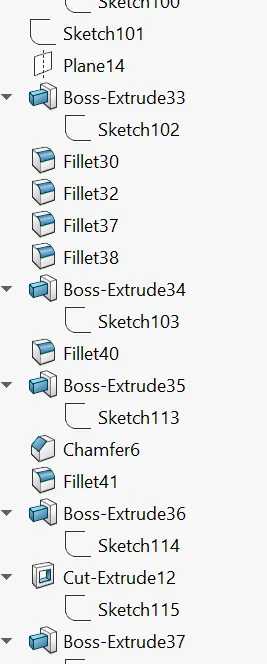
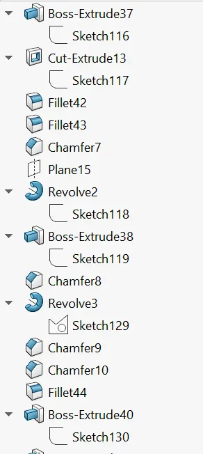
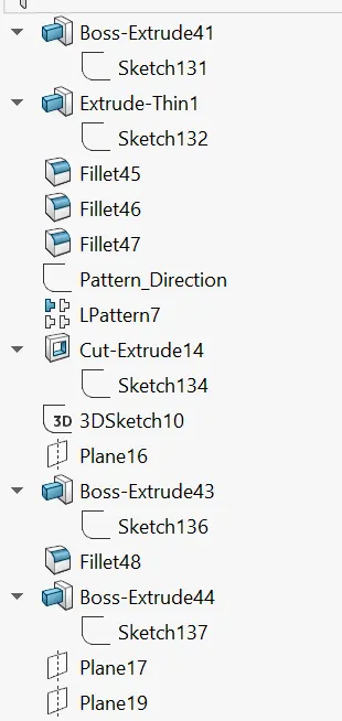
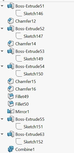
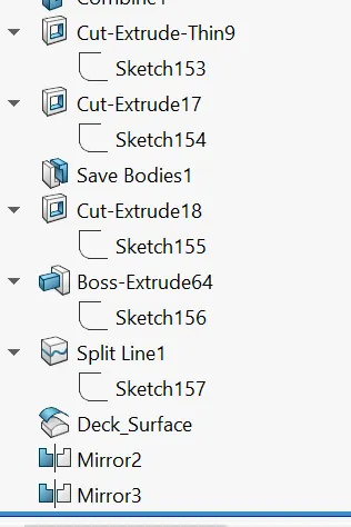
Features Used:
1.Sketch: To create a any part We have start with Skecth in a 2-D Plane.
The Sketch we have created by giving the proper dimensions is
- There are different options to create a Sketch by selecting the plane.[ Line,Circle,Spline,Rectangle,Arc,Ellipse,Slot,Fillet].
- To edit the sketch We have Trim Entities, Convert Entities,Offset Entities,Mirror entities, Linear,circular pattern etc.
- For Dimensioning We use Smart Dimension.
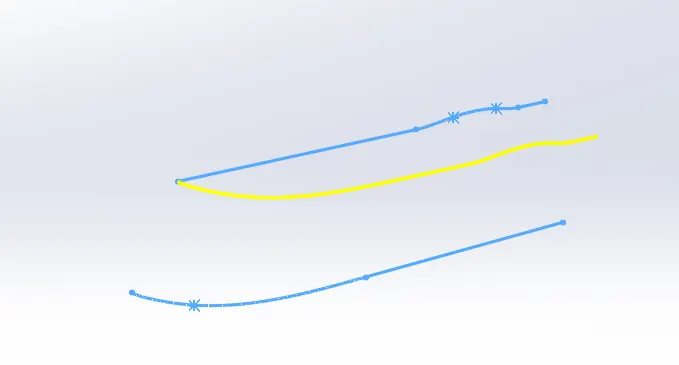
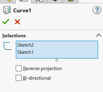
2.Pojected Curve:Since we cannot draw a 3D curve, we used a projected curve. By drawing a curves in different palnes and applying a projection curve it gives a 3D curve.
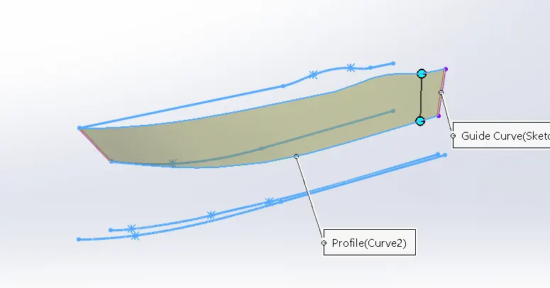
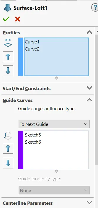
3.Lofted Surface: This feature creates a surface between two closed profiles and we have to give guide curves inorder to govern the profiles.
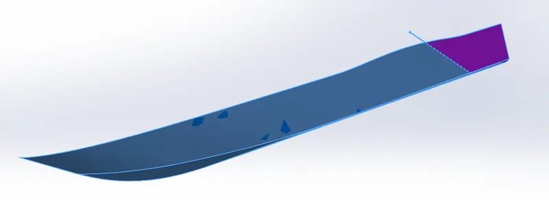
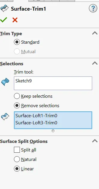
4.Surface Trim: This feature is used to trim the un wanted surface material
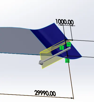
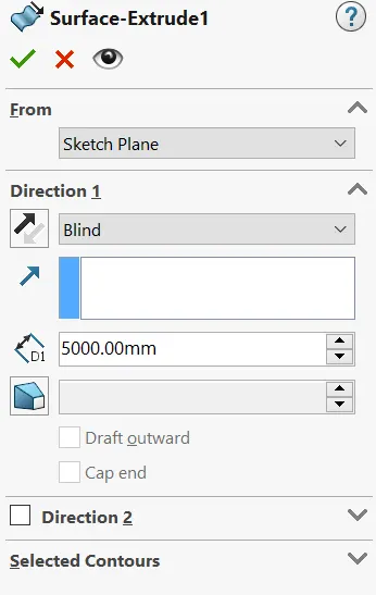
5.Extrude Surface: This feature is used to Convert a closed 2D sketch into 3D Sketch.
We have another options to extrude the sketch [Up to vertex, Up to surface, offset, Midplane etc]
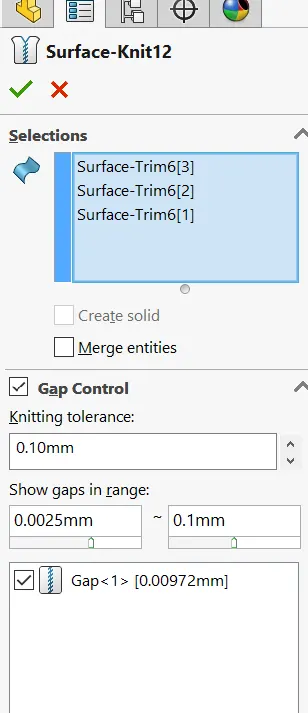
6.Knit Surface: This feature is uesd to to combine two or more faces and surfaces into one and by adjusting small gaps.
- It create a solid body when the knit surfaces form a closed body.
- Select Merge entities to merge faces with the same underlying geometry.
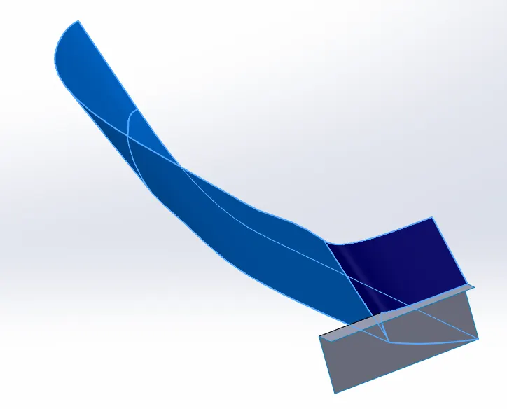
7.Surface Fill: This feature is used to fill the surface across the boundary.
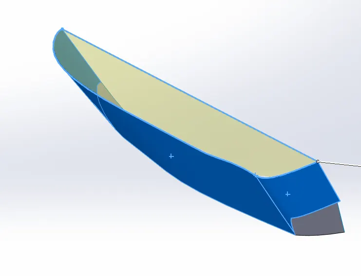
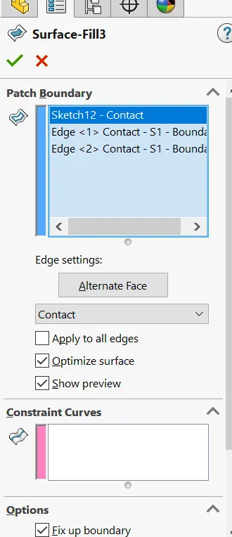
8.Boss Extrude: This feature is used to Convert a closed 2D sketch into 3D Sketch.
We have another options to extrude the sketch [Up to vertex, Up to surface, offset, Midplane etc]
9.Extrude Cut: This helps removing the solid body from the solid body
- Select the type of extrusion and give distance values.
- You can also select the parts by using selected contours.
10.Fillet: This feature is used to convert Sharp corner to round edges.
11.Chamfer: This feature is used to convert sharp edges into chamfers.
- Select the type of chamfer and enter the values.
- Select the edges and faces you want to chamfer.
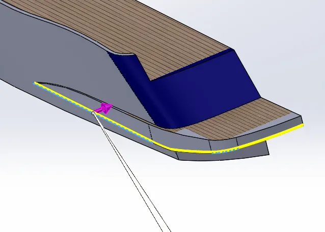
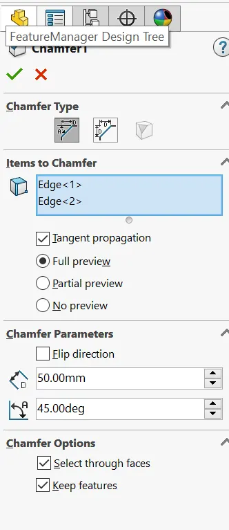
12.Sketch Pattern: This feature helps us to create a existing copy features and place them wherever you point in a sketch.
13.Swept Boss: To create a solid profile along the sepcified path
- Select the Profile and Path.
- Select the type of the profile.
13.Plane: Here we Inserted a palne by using reference geometry. We can select a reference to create a new plane.
14.Revolve Boss:This feature is used to create a closed revolving body with respect to axis.
- Select the closed sketch that needs to be revolved.
- Select the axis of revolution by which the sketch will revolve.
15.Dome: This feature creates a dome like structure on the flat face. This feature is majorly applied to faces. Select one or more planar or non-planar faces. You can apply dome to faces whose centroid lies outside the face. This allows you to apply domes to irregularly shaped contours.
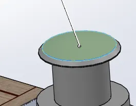
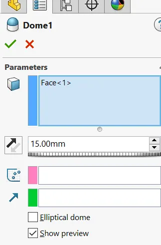
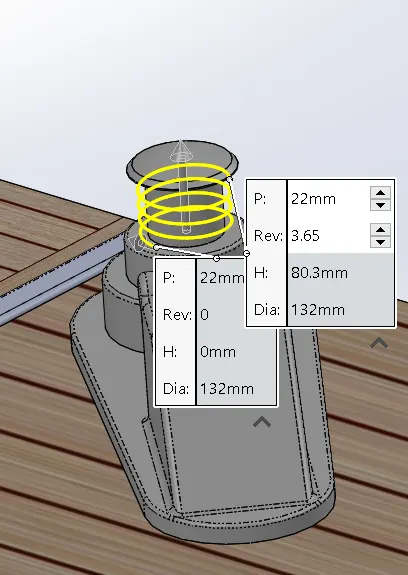
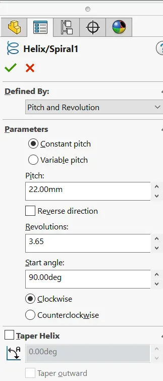
16.Helix/Spiral: This feature is used to form a spring along diameter
We will adjust no of revolutions, angle and pitch values
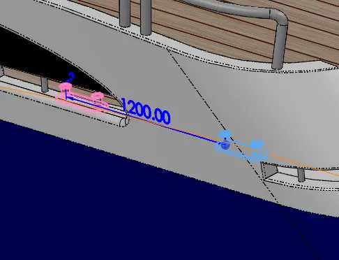
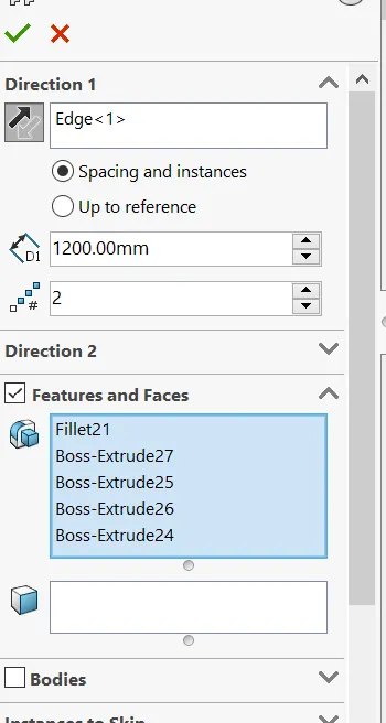
17.Linear Pattern:This feature is used to pattern the bodies linearly with respect to axis.
- Select a linear edge that you want to pattern in that direction.
- Assign values for insatances and distance between them.
- Choose bodies or features with respect to your choice.
18.3D Sketch: This feature is used to to draw a 3D Sketch
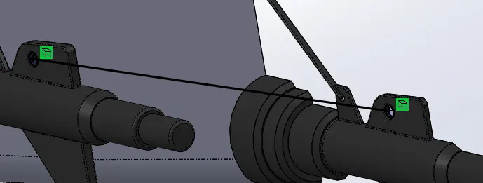
19.Mirror: This feature is used to mirror the parts with respect to the axis.
20.SplitLine: This feature is used to project an entity on to the other surfaces.
21.Appearance: Finally we added a different colors for different parts.
Garrage Door
Image of a Garrage door Feature Tree
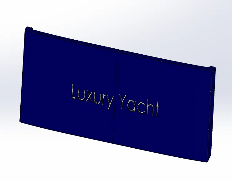
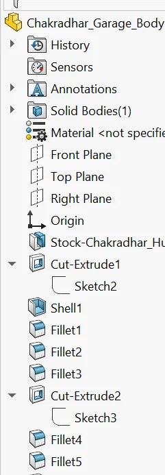
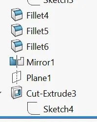
Features Used:
1.Sketch: To create a any part We have start with Skecth in a 2-D Plane.
2.Extrude Cut: This helps removing the solid body from the solid body
- Select the type of extrusion and give distance values.
- You can also select the parts by using selected contours.
3.Fillet: This feature is used to convert Sharp corner to round edges.
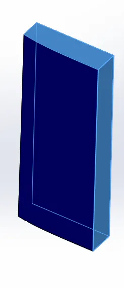
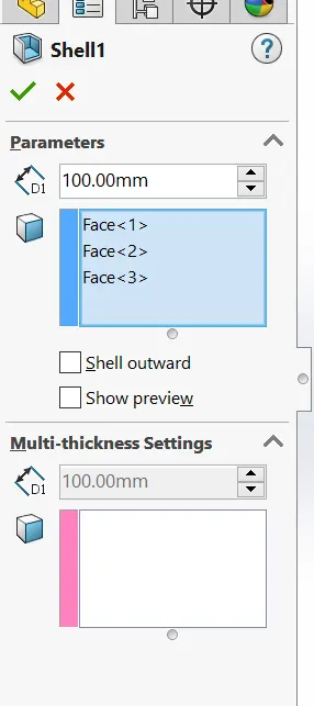
4.Shell:To convert solid body into hollow/ thin body.
5.Plane: Here we Inserted a palne by using reference geometry. We can select a reference to create a new plane.
6.Mirror: This feature is used to mirror the parts with respect to the axis.
7.Appearance: Finally we added a Color to the part.
Front Seat
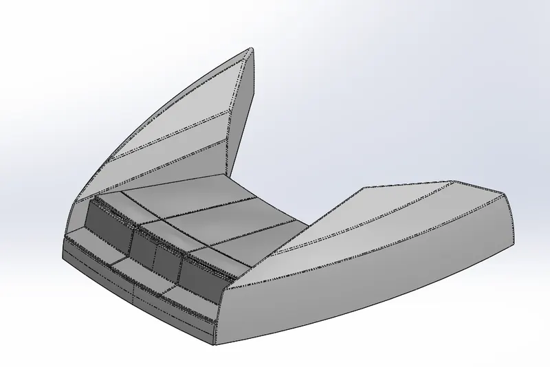
Image of a Front Seat
Feature Tree
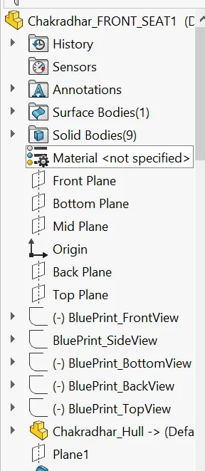
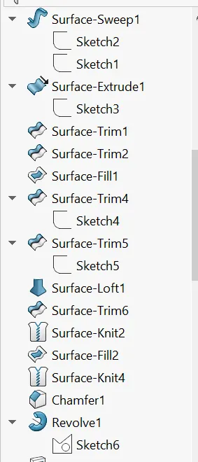
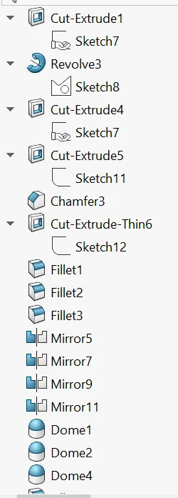
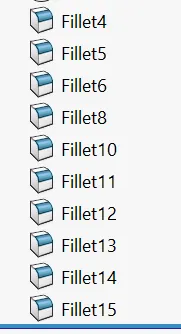
Features Used:
Before Starting the sketch we have to insert a hull surface body [Insert-Part-Hull]. It helps us to palce the seat on the surface of Hull.
1.Sketch: To create a any part We have start with Skecth in a 2-D Plane.
2.Plane: Here we Inserted a palne by using reference geometry. We can select a reference to create a new plane.
3.Surface sweep: This feature is used to generate a surface From a section curve positiones along the path.
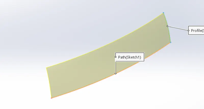
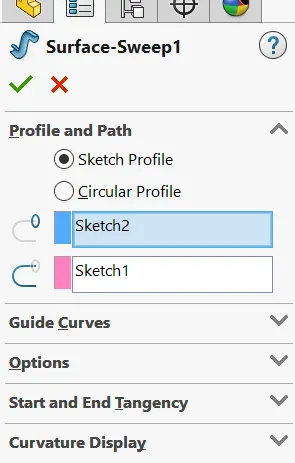
4.Extrude Surface: This feature is used to Convert a closed 2D sketch into 3D Sketch.
We have another options to extrude the sketch [Up to vertex, Up to surface, offset, Midplane etc]
5.Surface Trim: This feature is used to trim the un wanted surface material.
6.Surface Fill: This feature is used to fill the surface across the boundary.
7.Lofted Surface: This feature creates a surface between two closed profiles and we have to give guide curves inorder to govern the profiles.
8.Knit Surface: This feature is uesd to to combine two or more faces and surfaces into one and by adjusting small gaps.
- It create a solid body when the knit surfaces form a closed body.
- Select Merge entities to merge faces with the same underlying geometry.
9.Chamfer: This feature is used to convert sharp edges into chamfers.
- Select the type of chamfer and enter the values.
- Select the edges and faces you want to chamfer.
10.Revolve Boss:This feature is used to create a closed revolving body with respect to axis.
- Select the closed sketch that needs to be revolved.
- Select the axis of revolution by which the sketch will revolve.
11.Extrude Cut: This helps removing the solid body from the solid body
- Select the type of extrusion and give distance values.
- You can also select the parts by using selected contours.
12.Fillet: This feature is used to convert Sharp corner to round edges.
13.Dome: This feature creates a dome like structure on the flat face. This feature is majorly applied to faces. Select one or more planar or non-planar faces. You can apply dome to faces whose centroid lies outside the face. This allows you to apply domes to irregularly shaped contours.
14.Mirror: This feature is used to mirror the parts with respect to the axis.
15.Appearance: Finally we added a Color to the part.
Middle Seat:
Image of Middle Seat Feature Tree:
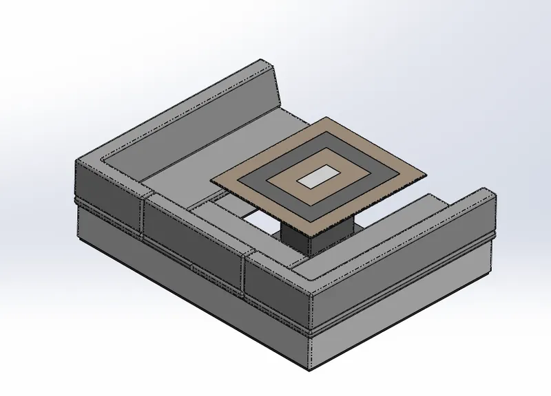
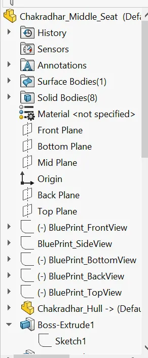
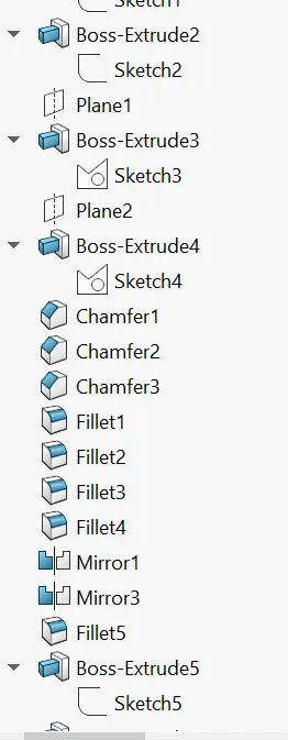
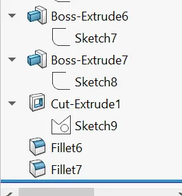
Features Used:
Before Starting the sketch we have to insert a hull surface body [Insert-Part-Hull]. It helps us to palce the seat on the surface of Hull.
1.Sketch: To create a any part We have start with Skecth in a 2-D Plane.
2.Boss Extrude: This feature is used to Convert a closed 2D sketch into 3D Sketch.
We have another options to extrude the sketch [Up to vertex, Up to surface, offset, Midplane etc]
3.Plane: Here we Inserted a palne by using reference geometry. We can select a reference to create a new plane.
4.Chamfer: This feature is used to convert sharp edges into chamfers.
- Select the type of chamfer and enter the values.
- Select the edges and faces you want to chamfer.
5.Fillet: This feature is used to convert Sharp corner to round edges.
6.Extrude Cut: This helps removing the solid body from the solid body
- Select the type of extrusion and give distance values.
- You can also select the parts by using selected contours.
7.Mirror: This feature is used to mirror the parts with respect to the axis.
8.Appearance: Finally we added a Color to the part.
Rear Seat:
Image of a Rear Seat
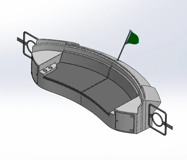
Feature Tree:
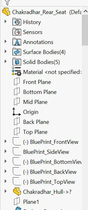
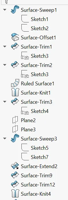
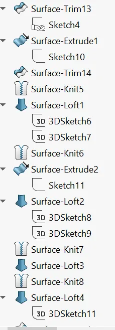
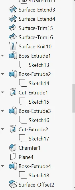
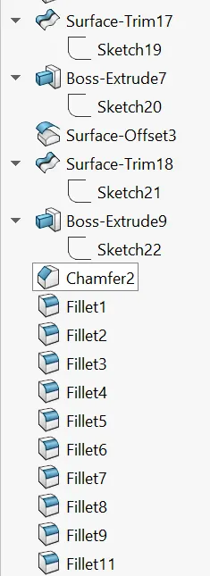
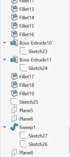
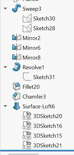
Features Used:
Before Starting the sketch we have to insert a hull surface body [Insert-Part-Hull]. It helps us to palce the seat on the surface of Hull.
1.Sketch: To create a any part We have start with Skecth in a 2-D Plane.
2.Plane: Here we Inserted a palne by using reference geometry. We can select a reference to create a new plane.
3.Surface sweep: This feature is used to generate a surface From a section curve positiones along the path.
4.Surface Offset: This Feature is used to offset a surface up to a certain distance by assinging the value.
5.Lofted Surface: This feature creates a surface between two closed profiles and we have to give guide curves inorder to govern the profiles.
6.Surface Trim: This feature is used to trim the un wanted surface material
7.Extrude Surface: This feature is used to Convert a closed 2D sketch into 3D Sketch.
We have another options to extrude the sketch [Up to vertex, Up to surface, offset, Midplane etc]
8.Knit Surface: This feature is uesd to to combine two or more faces and surfaces into one and by adjusting small gaps.
- It create a solid body when the knit surfaces form a closed body.
- Select Merge entities to merge faces with the same underlying geometry.
9.Ruled Surface: The Ruled Surface feature creates surfaces that extend out in a specified direction from selected edges.
10.Extend Surface: This feature is used to extend the surface up to a certain distance.
11.3D Sketch: This feature is used to to draw a 3D Sketch.
12.Boss Extrude: This feature is used to Convert a closed 2D sketch into 3D Sketch.
We have another options to extrude the sketch [Up to vertex, Up to surface, offset, Midplane etc]
13.Extrude Cut: This helps removing the solid body from the solid body
- Select the type of extrusion and give distance values.
- You can also select the parts by using selected contours.
14.Chamfer: This feature is used to convert sharp edges into chamfers.
- Select the type of chamfer and enter the values.
- Select the edges and faces you want to chamfer.
15.Fillet: This feature is used to convert Sharp corner to round edges.
16.Swept Boss: To create a solid profile along the sepcified path
- Select the Profile and Path.
- Select the type of the profile.
17.Mirror: This feature is used to mirror the parts with respect to the axis.
18.Appearance: Finally we added a Color to the part.
Superstructure:
Image of a Supertructure:
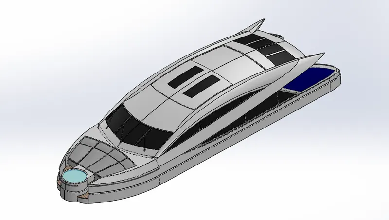
Feature Tree
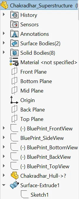
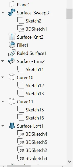
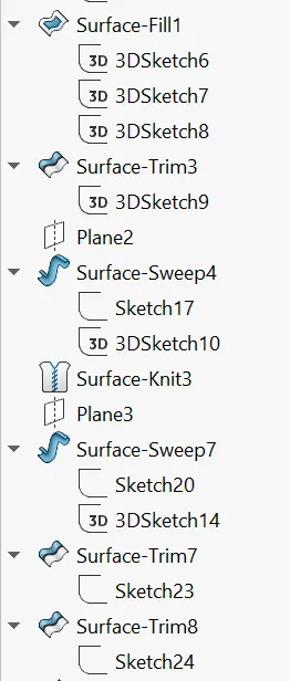
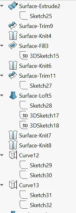
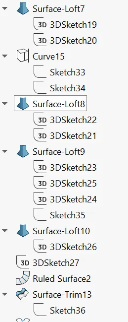
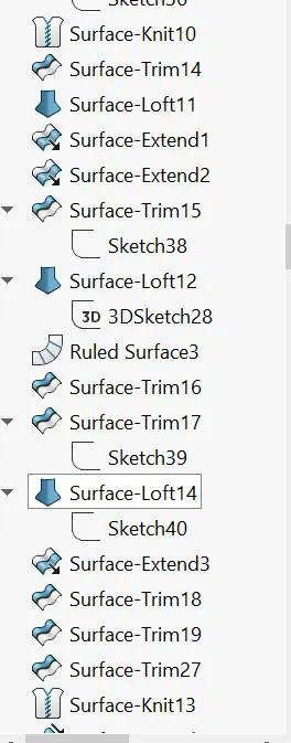
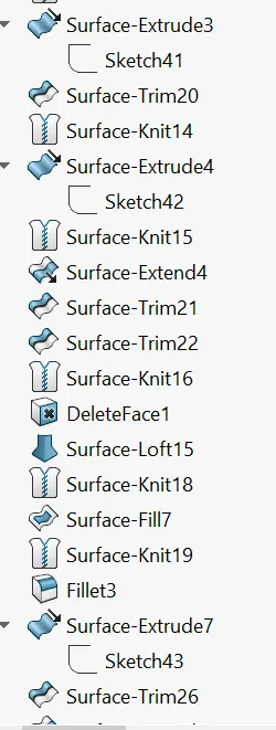
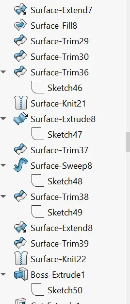
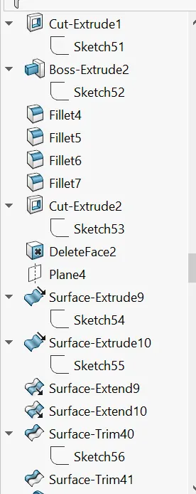
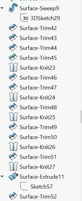
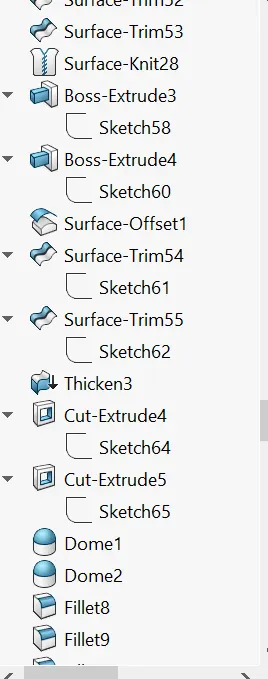
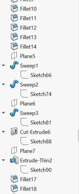
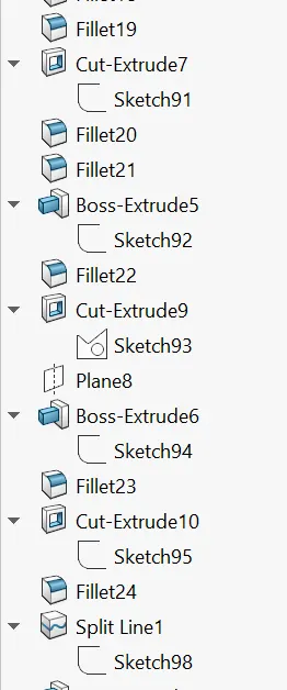
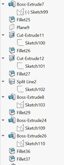
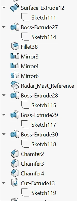
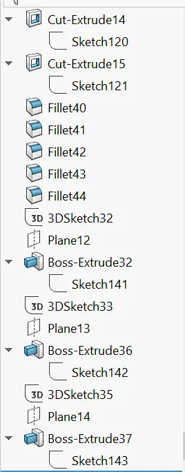
Features Used:
Before Starting the sketch we have to insert a hull surface body [Insert-Part-Hull]. It helps us to palce the superstructure on the surface of Hull.
1.Sketch: To create a any part We have start with Skecth in a 2-D Plane.
2.Extrude Surface: This feature is used to Convert a closed 2D sketch into 3D Sketch.
We have another options to extrude the sketch [Up to vertex, Up to surface, offset, Midplane etc]
3.Plane: Here we Inserted a palne by using reference geometry. We can select a reference to create a new plane.
4.Surface sweep: This feature is used to generate a surface From a section curve positiones along the path.
5.Knit Surface: This feature is uesd to to combine two or more faces and surfaces into one and by adjusting small gaps.
- It create a solid body when the knit surfaces form a closed body.
- Select Merge entities to merge faces with the same underlying geometry.
6.Lofted Surface: This feature creates a surface between two closed profiles and we have to give guide curves inorder to govern the profiles.
7.Surface Trim: This feature is used to trim the un wanted surface material.
8.Ruled Surface: The Ruled Surface feature creates surfaces that extend out in a specified direction from selected edges.
9.Pojected Curve:Since we cannot draw a 3D curve, we used a projected curve. By drawing a curves in different palnes and applying a projection curve it gives a 3D curve.
10.Surface Fill: This feature is used to fill the surface across the boundary.
11.Extend Surface: This feature is used to extend the surface up to a certain distance.
12.3D Sketch: This feature is used to to draw a 3D Sketch.
13.Surface Offset: This Feature is used to offset a surface up to a certain distance by assinging the value.
14. Delete Face: This Feature is used to remove the unwanted face part. By selecting the faces We can delete it.
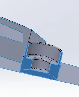
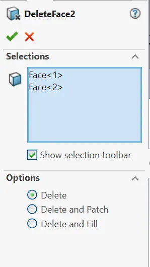
15.Dome: This feature creates a dome like structure on the flat face. This feature is majorly applied to faces. Select one or more planar or non-planar faces. You can apply dome to faces whose centroid lies outside the face. This allows you to apply domes to irregularly shaped contours.
16.Boss Extrude: This feature is used to Convert a closed 2D sketch into 3D Sketch.
We have another options to extrude the sketch [Up to vertex, Up to surface, offset, Midplane etc]
17.Extrude Cut: This helps removing the solid body from the solid body
- Select the type of extrusion and give distance values.
- You can also select the parts by using selected contours.
18.Swept Boss: To create a solid profile along the sepcified path
- Select the Profile and Path.
- Select the type of the profile.
19.Fillet: This feature is used to convert Sharp corner to round edges.
20.Chamfer: This feature is used to convert sharp edges into chamfers.
- Select the type of chamfer and enter the values.
- Select the edges and faces you want to chamfer.
21.Split Line: This feature is used to project an entity on to the other surfaces.
22.Mirror: This feature is used to mirror the parts with respect to the axis.
23.Appearance: Finally we added a Color to the part.
Radarmast
Image of a Radarmast
Feature Tree
Features Used:
1.Sketch: To create a any part We have start with Skecth in a 2-D Plane.
2.Plane: Here we Inserted a palne by using reference geometry. We can select a reference to create a new plane.
3.Boss Extrude: This feature is used to Convert a closed 2D sketch into 3D Sketch.
We have another options to extrude the sketch [Up to vertex, Up to surface, offset, Midplane etc]
4.Revolve Boss:This feature is used to create a closed revolving body with respect to axis.
- Select the closed sketch that needs to be revolved.
- Select the axis of revolution by which the sketch will revolve.
5.Shell:To convert solid body into hollow/ thin body.
6.Fillet: This feature is used to convert Sharp corner to round edges.
7.Chamfer: This feature is used to convert sharp edges into chamfers.
- Select the type of chamfer and enter the values.
- Select the edges and faces you want to chamfer.
8.Mirror: This feature is used to mirror the parts with respect to the axis.
9.Appearance: Finally we added a Color to the part.
6.Assembly
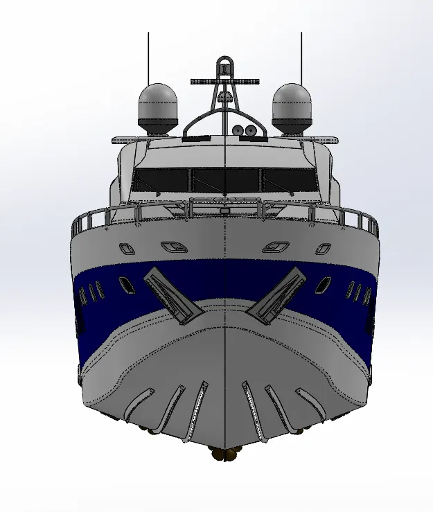
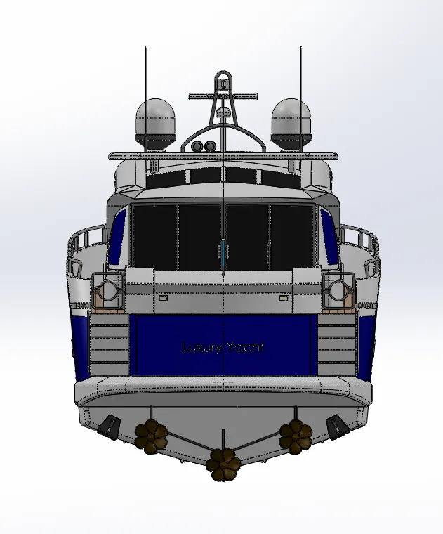
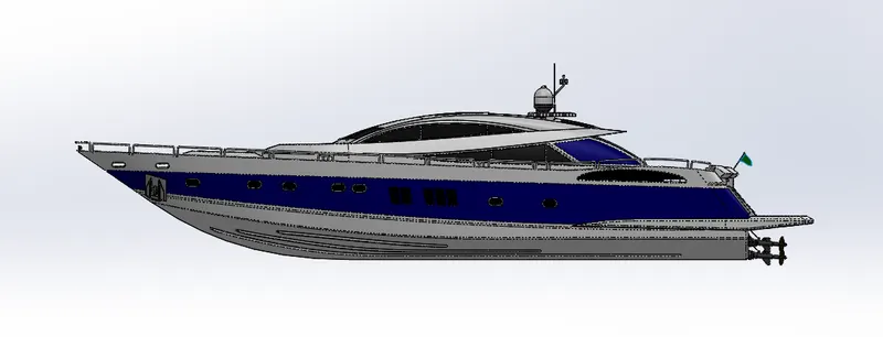
Assembly Images
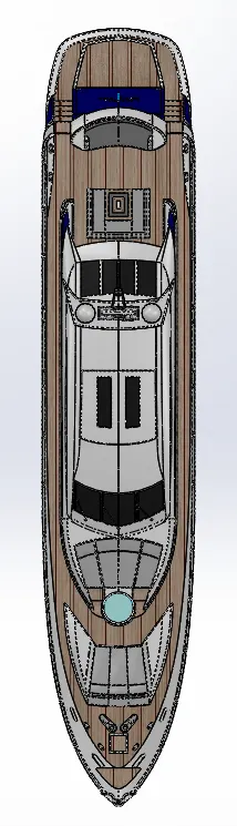
Front View Back View
Side View Top View
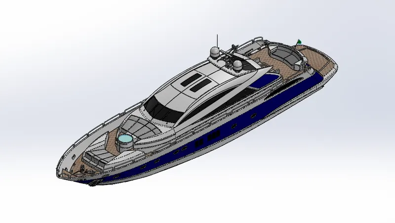
 Isometric View
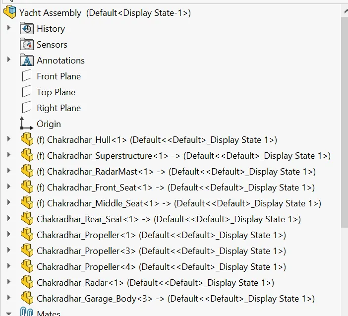
Feature Tree
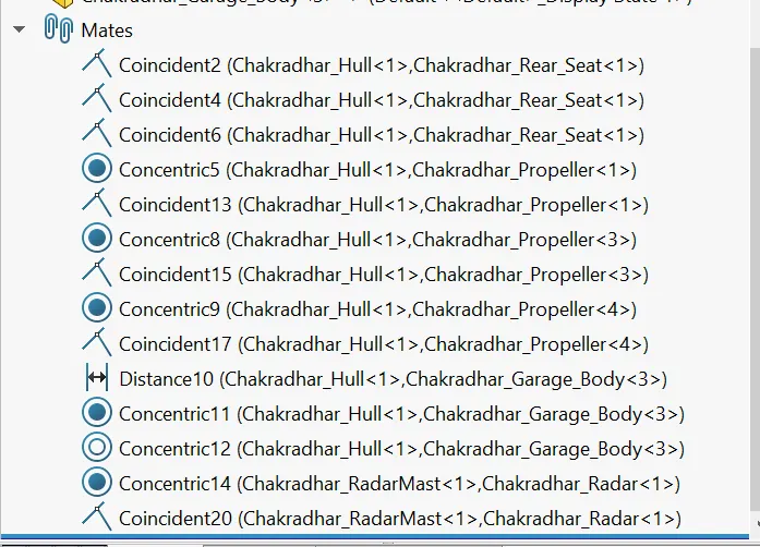
Features Used:
- Firstly We insert a hull part, it will automatically fix.
- And import the Supertructure and click ok without clicking anywhere. It will automatically fixed to the hull because we used surface of the hull to create superstructure.
- Similary Import the Radarmast, Front seat, Middle Seat. It will automatically fix to the hull
- Remaining parts are fixed by using Respective mates.
Mates Used:
- Coincident: Makes two surfaces coincident with each other.
- Concentric: Applies concentric relation between two different circular profiles.
- Distance:It Fixes two faces/edges/points at a specified distance.
7. Rendering:
- Using Photoview 360:
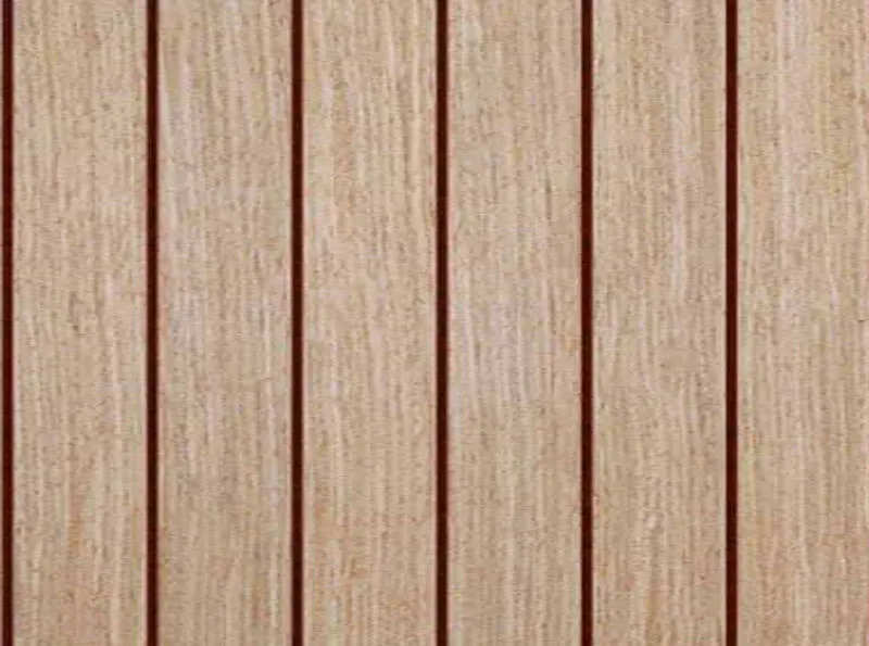
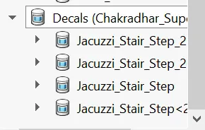
- We can apply decals
Here We applied Decals to two parts
- Hull
Main floor Yacht Front Stair step
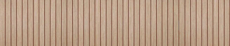
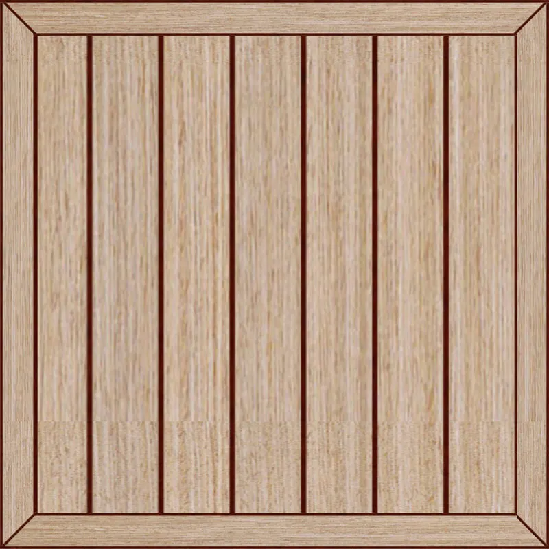
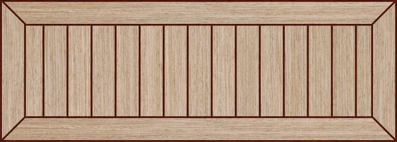
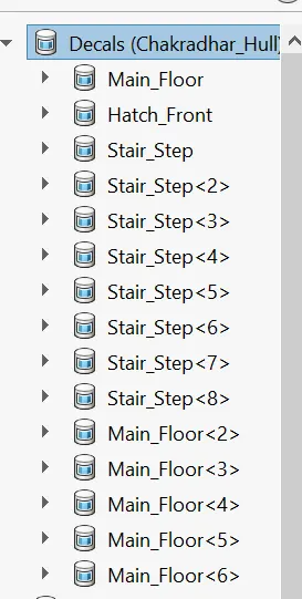
- SuperStructure
Jacuzzi Stair Step Jacuzzi Stair Step2
- We can view scenes, and add lights and cameras.
Solidworks Visualize:
We impor the AmericanChopper model into the Solidworks visualize and applied different renders on it.
Before rendering the mage we have set the settings
Settings:
- First we have to import the American chopper assembly by drop down the file menu button.
A) View Manager
- Rendering Selection
- Turntable
- Selection tool
- Object Manupulation tools
- Camera tools
- View Presets
- Output tools

B) Model Settings
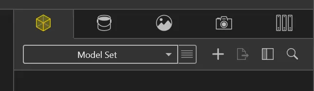
- Apperance: To add Color to the model
- Scene: To add diiferent scenes in background and environment to the model.
- Camera: To add different views to the models.
- Library: To browse and get different appearances, scenes from either local or cloud storage.
C) Rendered Images
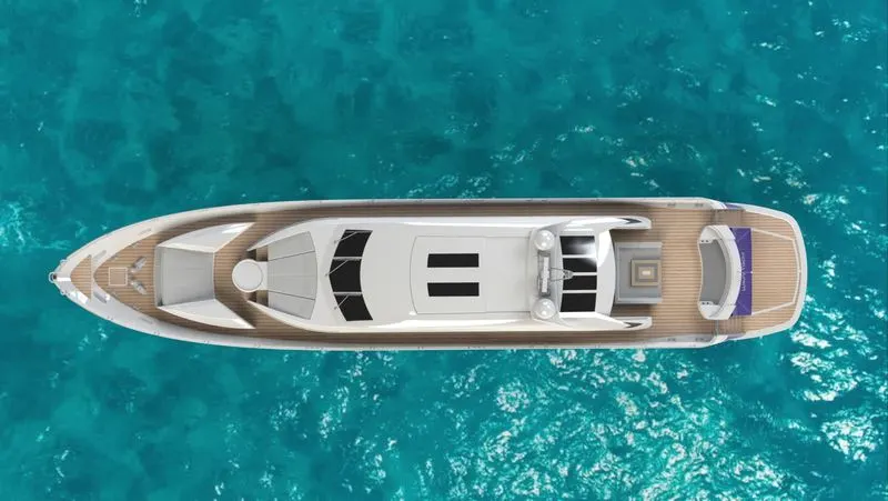
Here We Have rendered 5 Images
Isometric View
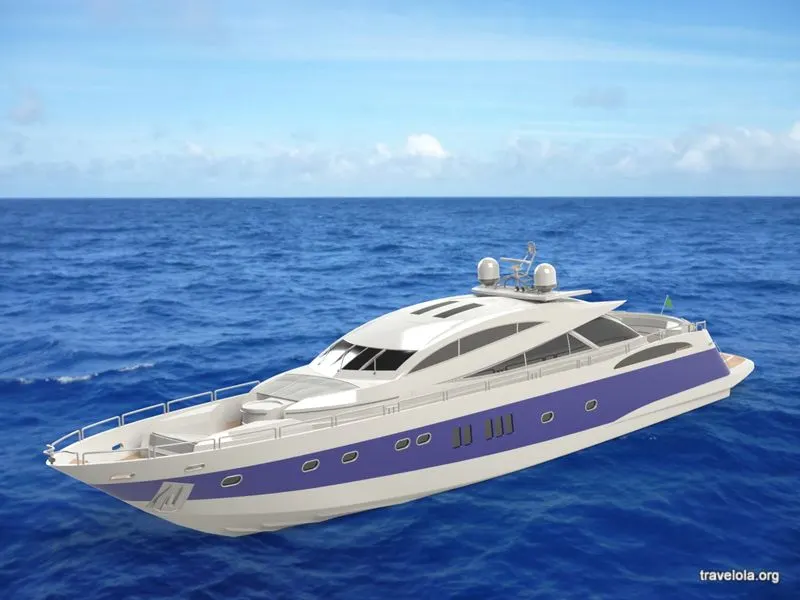
Camera View
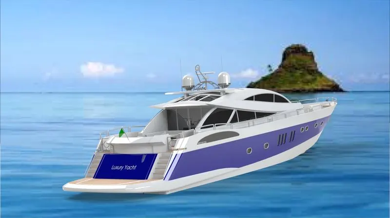
Back View
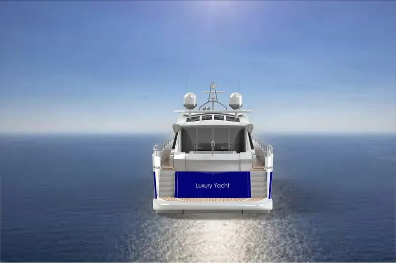
Front View
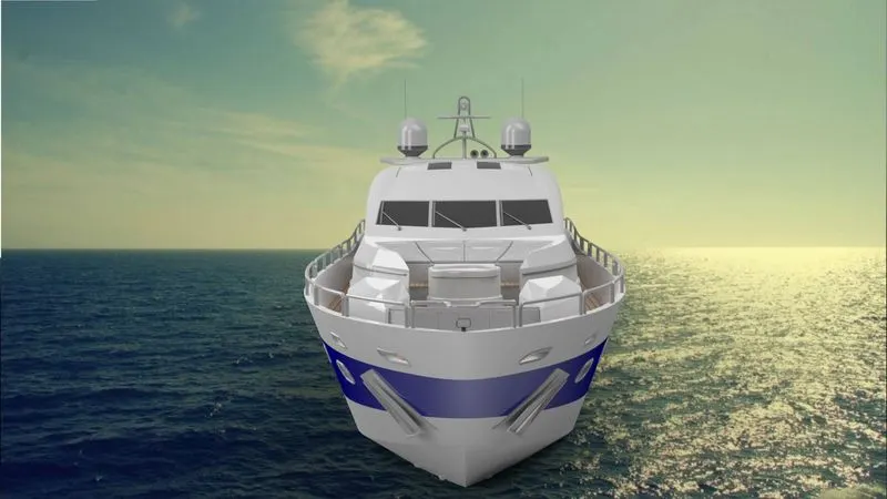
Top View
8.Conclusion:
- All individual parts are created in Solidworks part mode and assemble all parts in Solidworks assembly mode.
- Render the images is done in Solidworks Visuvalization.