Radar Mast & Final Assembly of Yacht
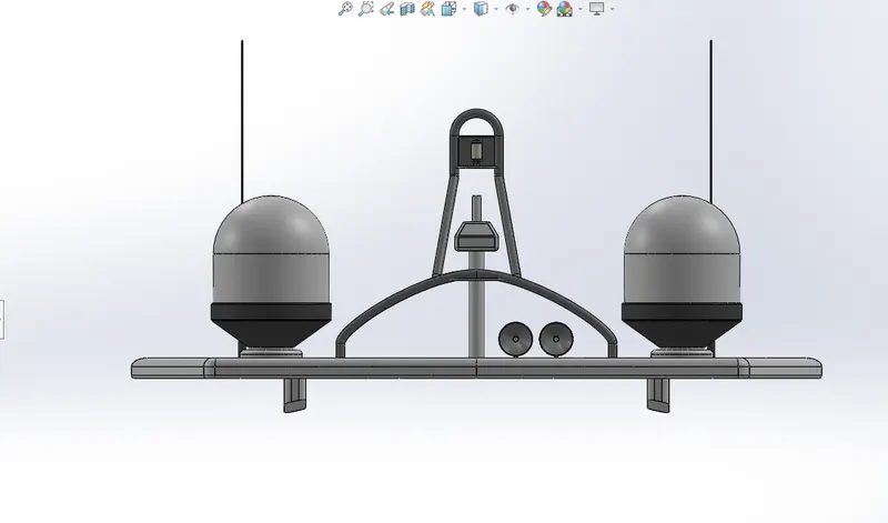
FRONT VIEW RADAR MAST
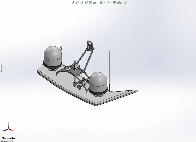
ISOMETRIC VIEW RADAR MAST
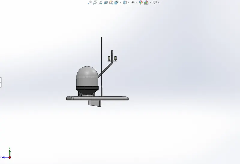
SIDE VIEW RADAR MAST
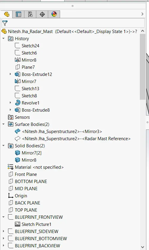
FEATURE TREE PART 1
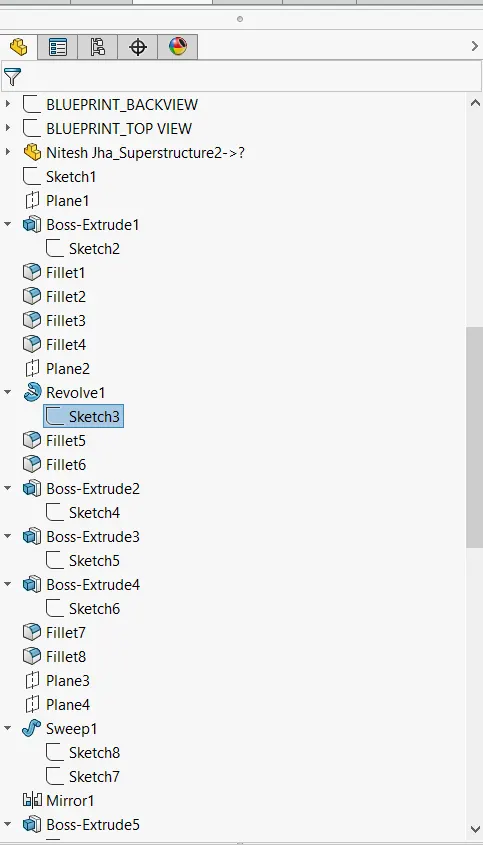
FEATURE TREE PART 2
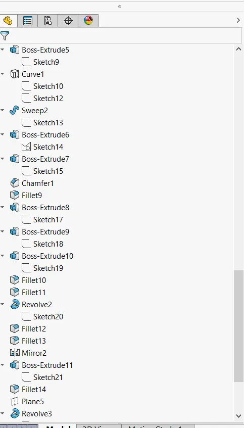
FEATURE TREE PART 3
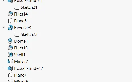
FEATURE TREE PART 4
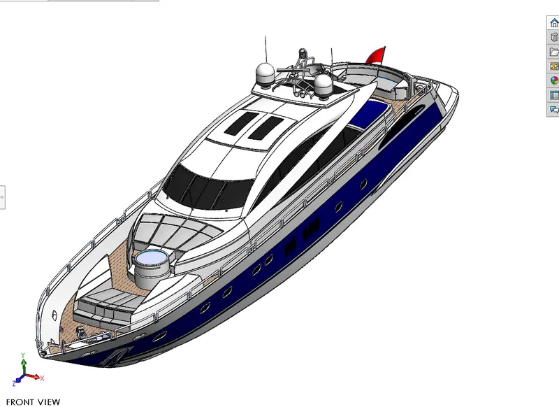
ISOMETRIC VIEW YACHT
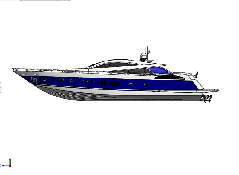
SIDE VIEW YACHT
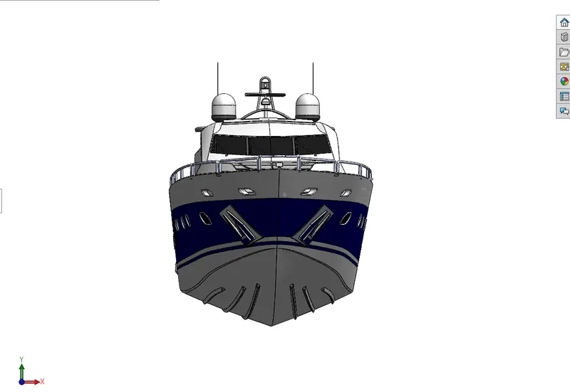
FRONT VIEW YACHT
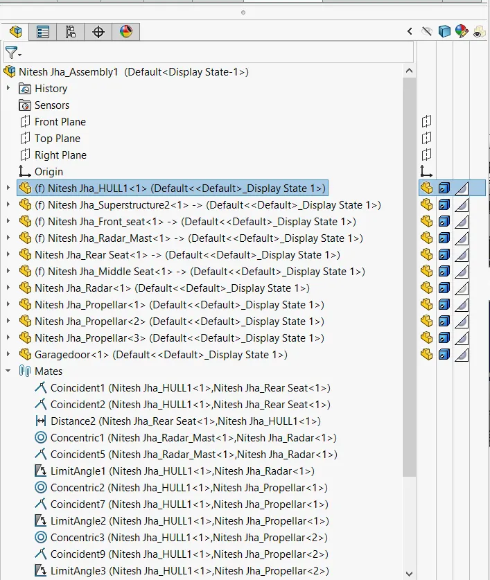
FEATURE TREE PART 1
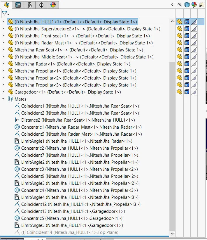
FEATURE TREE PART 2
Sunseeker Predator Yacht
Objective : To design and render different parts of Sunseeker Yacht using the surface features and the various tools available in SOLIDWORKS.
Introduction
The modeling of Sunseeker Yacht becomes easier with the help of the various surface features available in SOLIDWORKS. These surface features provide different ways to model the desired surface of the structure, providing the right trajectory and curvature of a smooth surface.
The design of this yacht is divided into the modeling of various parts which are dimensioned according to the blueprint and with the help of sketch tools. The various parts are:-
- Propeller.
- Radar.
- Hull.
- Garage Door
- Front seat.
- Middle seat.
- Rear seat.
- Superstructure.
- Radar Mast.
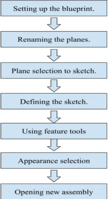
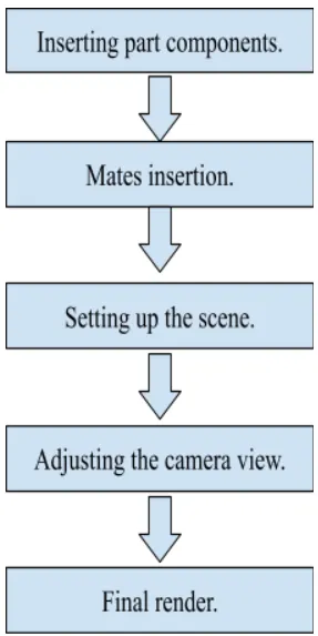
Design Methodology

Propeller
Sketch tools used:- Straight Line, Spline, Corner Rectangle, Smart Dimension.
Features used:- Revolved Base, Reference Plane, Lofted Boss, Fillet, Cut Extrude, Circular Pattern.
Straight Line:- This tool is used to draw straight lines, inclined lines, construction lines, midpoint line, and even arcs.
Spline:- It helps to sketch complex curves. This tool has a spline handle which helps to adjust the curvature of the curve according to the blueprint.
Corner Rectangle:- It helps to sketch a rectangle by selecting a point and then dragging the cursor to the required point.
Smart Dimension:- This tool helps to give or change the dimension of the lines, rectangle, arc, splines, circle.
Revolved Base:- It creates a solid feature by revolving a sketch contour around an axis. For using this feature the axis around which the solid feature will be created is selected, then the extent of revolve in degree is given and a closed contour is to be selected.
Reference Plane:- It helps to create a plane at any location where a sketch is to be made. In order to create a plane some references are to be selected such as the plane itself, or a line along with a vertex in order to specify where we want the plane to be and then distance from the selected plane or angle is given in order to fully define the plane. We can also specify the number planes we want to create and select the flip offset box to specify the direction in which the planes will be created equidistant to each other.
Lofted Boss:- It adds material between two or more selected profiles to create a solid feature. In order to create lofted boss the profiles are selected which are in different planes, then it is necessary to bring the green balls shown in the preview on the same side so that the solid feature is added in the same direction then the guide curves are selected if required as it guides the way material is added.
Fillet:- It helps to create rounded external and internal edges.There are four types of fillet, constant size fillet, variable size fillet, face fillet, and full round fillet.Here constant size fillet is done where in the “items to fillet” the edges which are to be filleted are selected and a radius is given keeping the tangent propagation option checked in.
Cut Extrude:- This feature removes the material in the shape of the selected sketch contour from the solid body. The sketch contour is selected first then in the property manager of cut extrude from the sketch plane is selected and to the blind is selected then the distance till which the material is removed is specified and by seeing the preview it is made sure that the cut extrude is directed towards the material.
Circular Pattern:- It is used to replicate the same features in a circular way with some distances between the patterns. First the axis about which the circular pattern is to be made is selected, then the angle is given, up to which the pattern is to be made, after that the number patterns to be made with equal spacing is given and lastly the features to be replicated are selected.
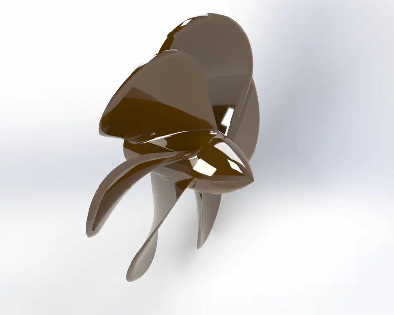
Propeller
Radar
Sketch tools used:- Straight Lines, Offset Entities, Circle, Smart Dimension, Polygon, Text, Point.
Features:- Boss Extrude, Fillet, Cut Extrude, Sketch Pattern, Mirror, Split Line.
Offset Entities:- It is used to offset sketch entities by a certain distance. The sketch is selected, then direction is specified for the offset and the distance of offset is given.
Circle:- It is used to sketch a circle, a point is selected for the centre of the circle and then it is dragged and release to define a radius.
Polygon:- It used to draw a polygon, it’s side can be changed
Text:- This tool is used to write a text on any set of continuous curves or edges.
Point:- It is used to make a point.
Boss Extrude:- It extrudes a closed sketch in one or two directions perpendicular to the sketch contour. It order to create boss extrude we need to specify from where the extrude will start and till where it needs to be done, this can be by giving the distance for blind, selecting the through all option, mid plane and many more ,one of these options are selected to get the required extrude. We can also check in the thin feature option to get the thin feature of the contour and a “direction 2” option to extrude in another direction opposite to the first direction.
Sketch Driven Pattern:- It is used to replicate features by using reference points as the centroid.
Mirror:- It is used to mirror bodies or features about a face or plane. In this first the plane or face is selected about which the mirror is to be done, and the bodies or features are selected which we want to mirror about the selected plane. If bodies are selected for mirror it is necessary to check in the merge solids options in order to convert it into a single body.
Split Line:- This feature is used to produce projection, silhouette, and intersection. Here this feature is used to project the text on the curved face of the radar.
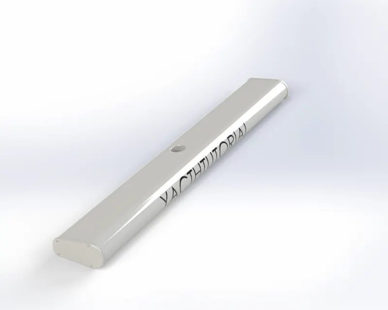
Radar
Hull
Sketch tools used:- Straight Lines, Spline, Smart Dimension, Offset Entities, Power trim, Fillet.
Features used:- Surface Loft, Surface Extrude, Projected Curve, Knit Surfaces, Trim Surface, Surface Fill, Shell, Boss Extrude, Cut Extrude, Fillet, Chamfer, Sweep Boss, Dome, Linear Pattern, Mirror.
Power Trim:- This tool is used to trim the sketch entity and make it coincident with another sketch.
Fillet:- It is used to make the corners rounded where two sketch entities intersect making it a tangent arc.
Surface Loft:- It creates a lofted surface between two or sketch profiles .In this we need to specify the start and end constraint and use the guide curves to guide the shape of the path.
Surface Extrude:- It is used to extrude the sketch or sketch contour in one or two directions to create a surface feature.We can specify the start and end of the extruded surface and its direction and extent.
Projected Curve:- This feature is used to form a curve in 3D by creating sketch profiles in two perpendicular planes and then selecting the profiles to form the curve. Both the sketches should be coincident with each other in order to get a projected curve.
Knit Surfaces:- This tool is used to combine two or more non intersecting surfaces into a single surface. The surface must join at an edge. If the resulting knit surface encloses a volume then we can create a solid body. The tolerance limit should be less than 0.1mm and after using knit features the intersecting edges should turn to black this ensures that there is no intersecting gap between the surface to create a solid body.
Trim Surface:- This feature is used to trim the surface where the surface intersects another surface, plane, or sketch. This is done by selecting the surface,plane or sketch as the trim tool and then the surface to be kept or removed is selected.
Surface Fill:- It forms a surface within the boundary formed by the sketches, curves, or curves. The edges or sketches are selected in sequence such as in clockwise or anticlockwise direction so the surface fill takes place in the desired way.
Shell:- It removes the material from a solid body to produce a thin walled feature. The thickness of the wall can be adjusted.
Chamfer:- It creates a bevel feature along an edge, a chain of tangent edges, or a vertex. It can be of following type: distance angle, distance distance, offset face, and face face.
Sweep Boss:- It sweeps a closed profile along an open or closed path to create a solid feature. The closed profile and the end of the path should be coincident with each other or have a pierce relation for the sweep to take place. The option of guide curve and profile orientation option to create a variety of shapes.
Linear Pattern:- It is used to replicate feature patterns, faces, bodies in one or more linear directions. A particular direction is selected along which the features are replicated, then the number of times it should be replicated at equal instances is given and lastly the features are selected.
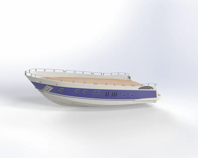
Hull
Garage Door
Sketch tools used:- Straight Lines, Smart Dimension, Text, Circle.
Features used:- Cut Extrude, Shell, Fillet, Mirror, Reference Plane.
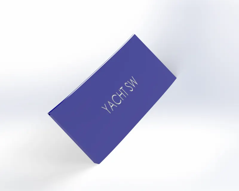
Garage Door
Front Seat
Sketch tools used:- Spline, Straight Line, Convert Entities, Trim, Corner Rectangle, Offset Entities.
Features used:- Cut Extrude, Surface Fill, Sweep boss, Surface loft, Revolve Base, Surface Trim, Surface Knit, Chamfer, Surface Extrude, Surface Sweep, Mirror, Dome, Fillet.
Convert Entities:- It converts the selected edges or sketch entities into identical entities and projects them onto the plane or face which is selected for sketching.
Surface Sweep:- This feature sweeps a closed profile along a closed or open path to form a surface feature and guide curves are selected to specify the shape of the surface,care should be taken to keep the green balls on the same after looking at the preview.
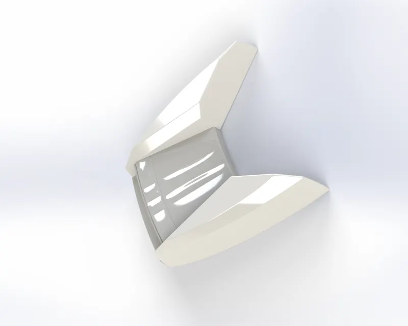
Front Seat
Middle Seat
Sketch tools used:- Straight Lines, Offset Entities, Trim.
Features used:- Cut Extrude, Boss Extrude, Fillet, Chamfer, Mirror, Reference Geometry Plane.
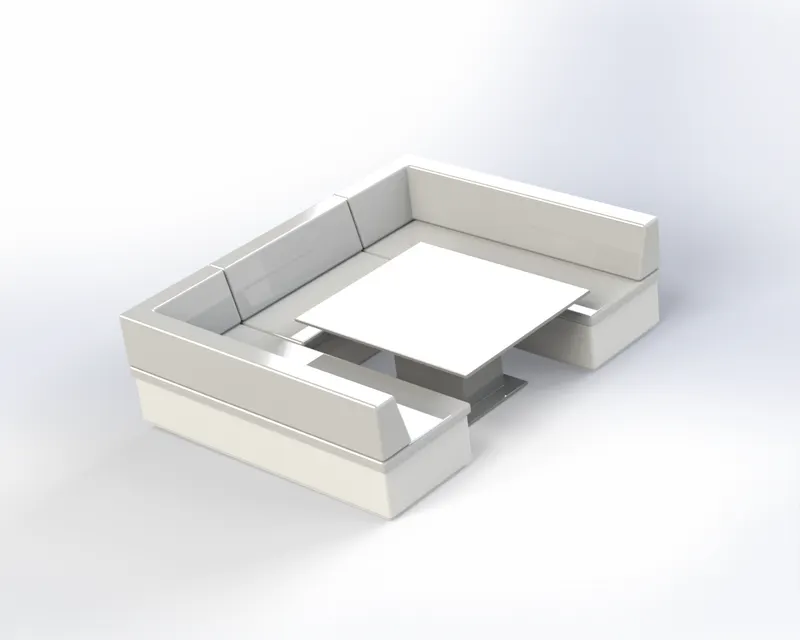
Middle Seat
Rear Seat
Sketch tools used:- Splines, Offset Entities, Convert Entities, Circle, Trim.
Features used:- Ruled Surface, Surface extend, Surface offset, Surface Trim, Cut Extrude, Reference Geometry Plane, Boss Extrude, Surface Knit, Surface Loft, Surface Extrude, Surface Sweep.
Surface Extend:- This features extends edges or faces of the surface based on the end conditions and extension type.
Ruled Surface:- This tool inserts ruled surface in specified direction from edges.It can be tangent to surface, normal to surface, tapered to vector, perpendicular to the vector, and sweep.
Surface offset:- It is used to offset a surface at a certain distance from the selected surface.
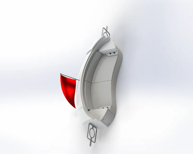
Rear Seat
Superstructure
Sketch tools used :- Straight Lines, Splines, Convert Entities, Power Trim, Offset Entities, 3D Sketch.
Features used:- Surface Extrude, Surface Sweep, Surface Knit, Fillet, Ruled Surface, Surface Trim, Projected Curve, Surface Loft, Surface Fill, Reference Geometry Plane, Surface Extend, Delete Face, Boss Extrude, Cut Extrude, Fillet, Mirror.
Delete Face:- This feature deletes face from solid or surface bodies. It can delete patch faces to form continuous surfaces.
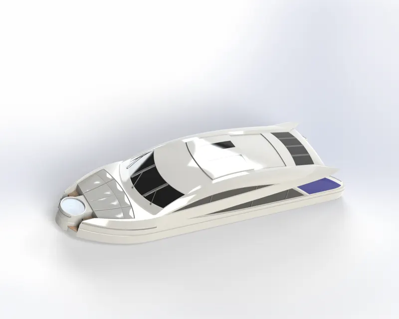
Superstructure
Radar Mast
Sketch tools used:- Straight Lines, Splines, Circle, 3 Point Arc, Straight Slot.
Features used:- Boss Extrude, Fillet, Reference Geometry Plane, Revolve Base, Swept Boss, Mirror, Projected Curve, Chamfer, Dome, shell.
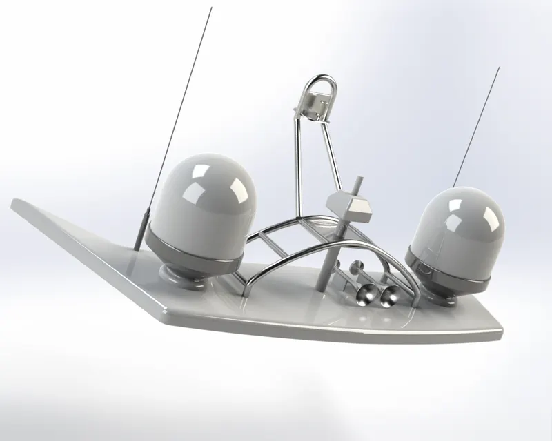
Radar Mast

TOP VIEW

CAMERA VIEW 1

CAMERA VIEW 2
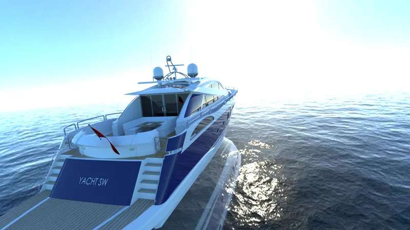
BACK VIEW

FRONT VIEW
Conclusion:
- While rendering the assembly, setting the yacht in different environments and scenes helps us to get a better idea of the scenes and adjustment that fits best with our yacht making it more appealing to the viewers attention.
- Increasing the number of passes of rendering and setting the quality to accurate helps to get a more realistic view of the yacht.
- Tolerance between the intersecting surface should be less than 0.1mm in order to knit the surface into a single continuous surface.
- Increasing the perspective and reducing the gamma helped to get more realistic renders of the yacht.