Photo Realistic Rendering
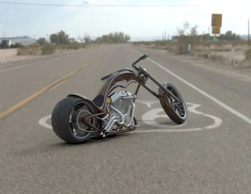
Title : AMERICAN CHOPPER
Objective : To design and render an American Chopper by designing each part of the Chopper and assembling them together into a single unit with help of different tools and features available in SOLIDWORKS.
Introduction : SOLIDWORKS comes with a lot of sketch tools and features. The common sketch tools used in the design of the different parts are Line, Circle, Spline, 3 point rectangle, Fillet, Mirror entities and the features used are Boss extrude, Cut extrude, Swept boss, Lofted boss, Mirror entities, Combine, Split, Linear pattern, Circular driven pattern, Circular pattern, Domb, Fillet, Chamfer, Trim, Extend.
Things to be kept in mind while designing are:-
- Sketch should be fully defined.
- One should be aware of the relations in the sketch as well as the relation of the part with the other parts.
- One should have a plan on how to use the different tools and features available in SOLIDWORKS in order to get desired design of the part.
Design Methodology :
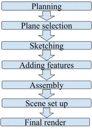
The first step is to design the different parts of American Chopper. These parts are Transmission belt, Kick stand, Foot pedal, Chain, Oil Tank, Chassis, Front fork, Front wheel, Front fender, Rear wheel, Rear fender, Gas tank, Engine. This done by renaming the planes in order to understand the different planes of the part while designing, then a particular plane is selected where the sketching is done by selecting the different sketch tools and understanding the different views of the parts in a particular plane, dimensions and relations are given to define the sketch completely and different features are applied to get 3d model of the part.
After the designing parts, the different parts are assembled together into a single unit, this is done by applying the various standard mates or advanced mates, and then decals are added to the body if required.
After the completion of the assembly Chopper is set for the scene editing by snapping the Chopper to the floor, then perspective is kept on, adjusting the position of the camera, and then the final rendering is done after setting the background scene, setting the brightness, gamma, shadow setting, and different appearances are set for the realistic look of the Chopper.
TRANSMISSION BELT
Sketch Tools used:- Line, arc,Smart dimension.
Features used:- Boss Extrude,Fillet.
Line : This tool is used to draw straight line,inclined line,construction line, midpoint line, and even arcs.
Smart dimension : This tool is used to give dimension to line, arc, circles, rectangle, and many other sketch tools.
Arc : This tool is used to draw semicircle and arc.
Boss Extrude : It helps to extrude a closed sketch drawn in plane in either direction of the axes.
Fillet : It helps to create rounded internal or external faces at the edges.
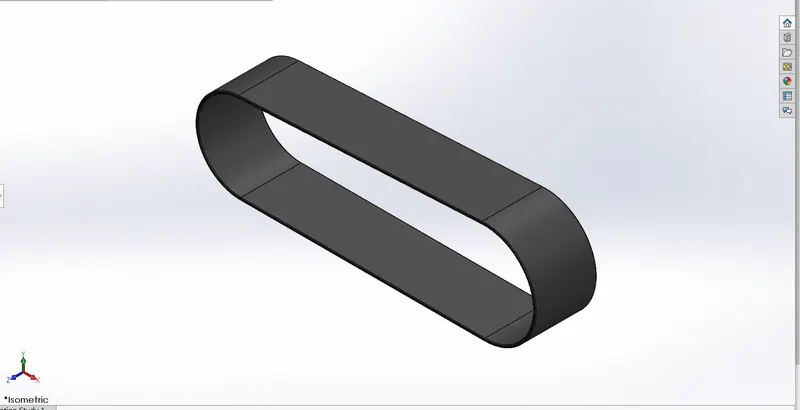
ISOMETRIC VIEW OF TRANSMISSION BELT
KICK STAND
Sketch Tools : Ellipse, Line, Circle, Arc.
Features used : Boss Extrude, Fillet, Split, Cut Extrude, Domb, Lofted Boss.
Ellipse : This tool is used to sketch an ellipse and uses two clicks to define the axes of the ellipse.
Circle : This tool is used to draw a circle and a perimeter circle.
Split : This tool is used to split cut the part of the body and creates multiple bodies from a single body.
Dome : Adds domes to the selected planar and non planar faces.
Cut Extrude : Cut extrudes a solid body in either direction.
Lofted Base : Adds material along a profile which is pierced into a closed contour.
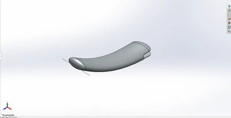
ISOMETRIC VIEW OF KICKSTAND.
PEDAL
Sketch Tools : Lines, Circle, Spline.
Features : Boss Extrude, Fillet, Domb, Chamfer, Linear Pattern, Revolve Base.
Spline : It helps to sketch a spline which has a directional handle, it helps to adjust the curvature in a certain region of the spline.
Chamfer : It creates a bevel feature along an edge.
Revolve Base : It adds material by revolving the sketch or contour about and an axis.
Linear Pattern : This tool helps to replicate a certain pattern in linear direction by setting a certain distance between the pattern.
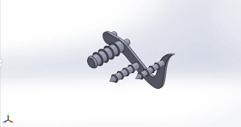
ISOMETRIC VIEW PEDAL
CHAIN
Sketch Tools : Straight slot, Line, Circle.
Features used : Boss Extrude, Fillet, Mirror Entities, Circular Driven Pattern.
Straight slot : It creates straight slot sketches.
Mirror Entities : It helps to mirror all the patterns about a plane and axis.
Circular Driven Pattern : It is used to replicate patterns along curved profiles.
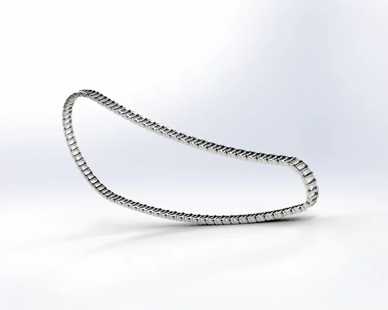
RENDERED VIEW CHAIN.
FRONT WHEEL
Sketch tools: Circle, Spline, Line
Features used : Cut Extrude, Boss Extrude, Revolve Base, Fillet, Chamfer, Revolve Base, Combine, Circular Pattern.
Combine : It combines two or more solid bodies.
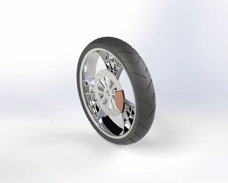
RENDERED VIEW OF FRONT WHEEL
FRONT FENDER
Sketch Tools: Line, Spline, Trim.
Features used : Revolve Base, Split, Fillet.
Trim : This tool is used to trim out the extra lines.
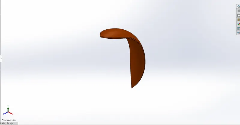
ISOMETRIC VIEW FRONT FENDER.
REAR FENDER.
Sketch Tools : Line , Spline, Trim.
Feature Tools : Fillet, Revolve Base.
Shell : Removes material from solid body making it hollow, having some wall thickness.
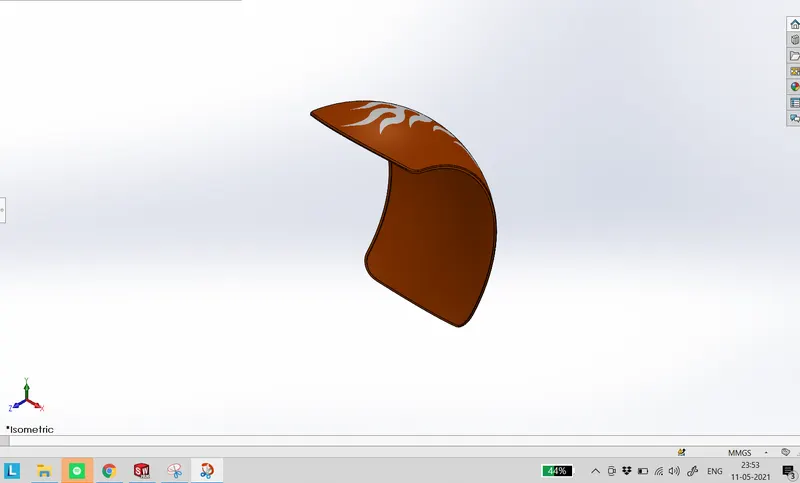
ISOMETRIC VIEW OF REAR FENDER.
OIL TANK
Sketch Tools: Spline, Trim, Extend Entities.
Features used : Boss Extrude , Combine, Fillet, Shell.
Shell : Removes material from solid body making it hollow, having some wall thickness.
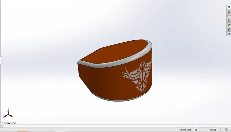
ISOMETRIC VIEW OF OIL TANK.
GAS TANK
Sketch Tools : Spline, Line, Split Line
Features used : Surface Sweep, Surface Trim, Surface Knit, Surface Loft, Fillet, Boundary Surface, Cut Sweep, Projected curve.
Surface Sweep : Creates surface by sweeping an open or closed path along an open or closed profile.
Surface Trim : Trims a surface where one surface intersects another surface.
Surface Knit : Combines the surface together.
Surface Loft : Creates a lofted surface along the specified guide curves.
Boundary Surface : Creates surface within the profiles that are tangent.
Cut Sweep : It cuts a solid body by sweeping a closed profile along an open profile.
Projected Curve : It is used to project curve in 3D by drawing the curves in other two planes having the same endpoints when viewed normal to the planes.
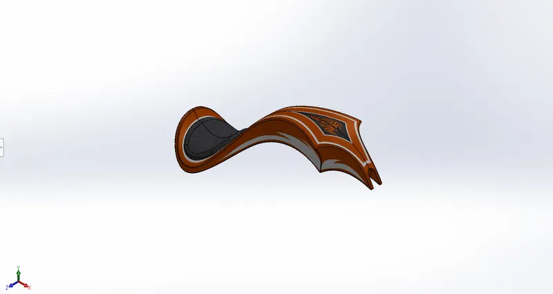
ISOMETRIC VIEW OF THE GAS TANK.
REAR WHEEL
Sketch Tools: Spline, Circle, Line, Trim Entities, Extend Entities.
Features used : Cut Extrude, Chamfer, Fillet, Revolve Base, Circular Pattern, Boss Extrude.
Circular Pattern : It replicates a pattern in circular direction.
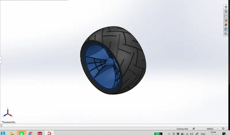
ISOMETRIC VIEW OF REAR WHEEL.
FRONT FORK
Sketch Tools : Line, Spline,Circle.
Features used : Cut Extrude, Revolve base, Fillet, Combine, Mirror, Sweep, Boss Extrude, Dome, Projected Curve.
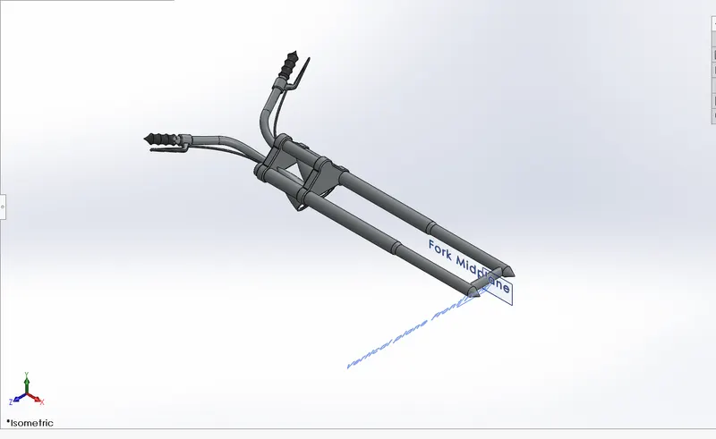
ISOMETRIC VIEW OF FRONT FORK.
ENGINE
Sketch Tools : Spline, Circle, Line,
Features used : Chamfer, Boss Extrude , Fillet, Circular Pattern, Revolve, Cut Extrude, Domb. Split, Mirror, Sweep, Combine, Projected Curve.
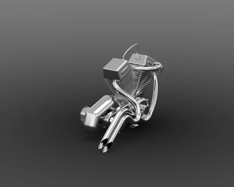
RENDERED VIEW OF ENGINE.
CHASSIS
Sketch Tools : Line, Spline, Circle.
Features used :Chamfer, Fillet, Sweep, Projected Curve, Mirror, Boss Extrude, Cut Extrude, Dome, Split, Combine, Revolve.
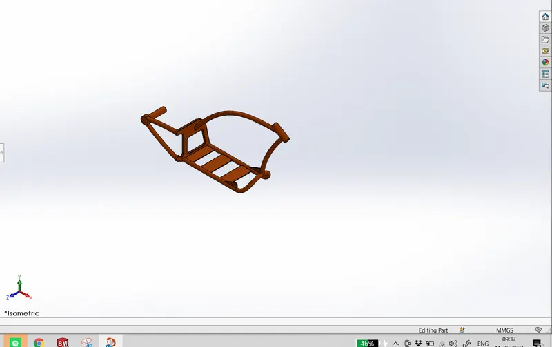
ISOMETRIC VIEW CHASSIS.
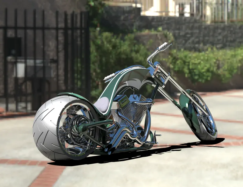
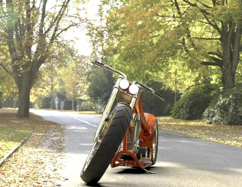
FRONT VIEW
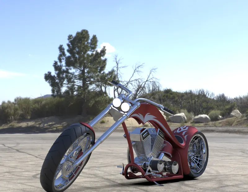
CAMERA VIEW
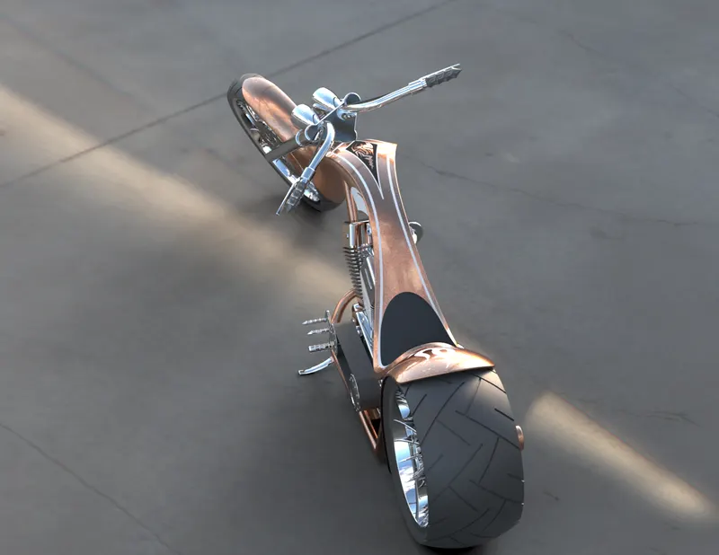
TOP VIEW
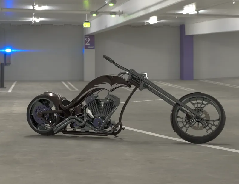
SIDE VIEW
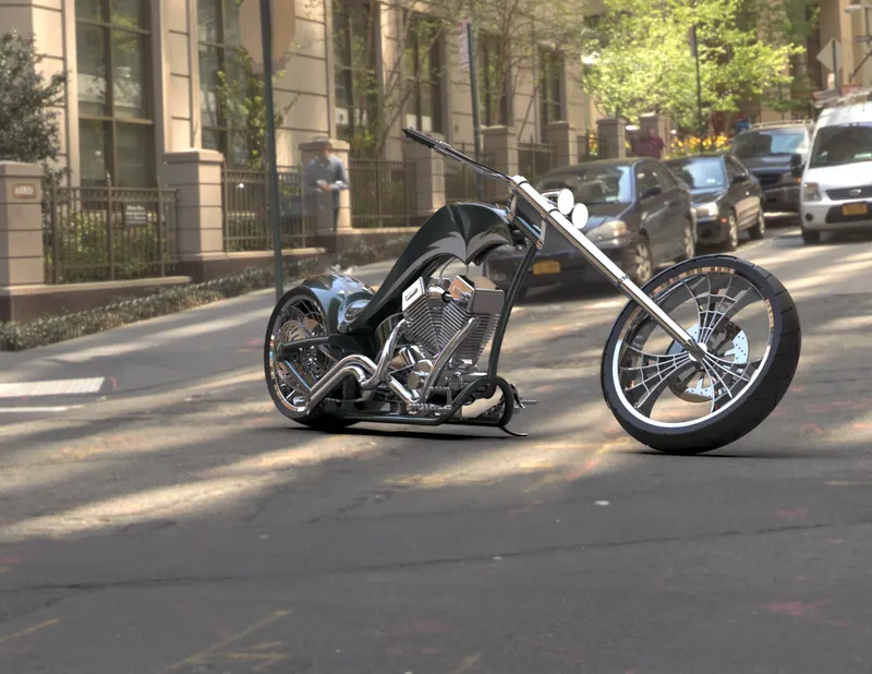
CONCLUSION
- While rendering the assembly, setting the chopper in different environments and scenes helps us to get a better idea of the scenes and adjustment that fits best with our Chopper making it more appealing to the viewers attention.
- Increasing the number of passes of rendering and setting the quality to accurate helps to get a more realistic view of the Chopper.
- While creating the different parts dimensions should be given carefully, so that later during the assembly of the parts mates can be done easily without creating any problems.