Advanced Sheet Metal Design Using NX Cad Challenge_2_Box Assembly
Box Assembly
Objective : To design a box using sheet metal modeling tools in NX CAD.
Introduction : The sheet metal application provides an environment for the design of the sheet metal. It’s various applications are aircraft bodies, automobile bodies, utensils used for domestic purposes and beverage cans.
We can create uniform thickness sheet metal parts using basic features such as flanges, tabs, bends, break corners, closed corners, and much more. In this project a box is made using the following features:
- Tabs.
- Flange.
- Closed Corner.
- Hem Flange.
- Mirror body.
- Unite.
- Dimple.
- Mirror feature.
- Unbend.
- Rebend.
- Bead.
- Datum plane.
- Break Corner.
- Normal cutout.
Design Methodology :
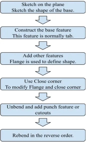
Features used :
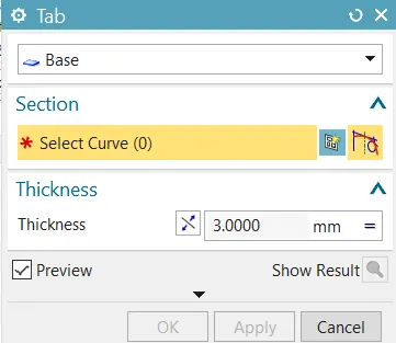
Tab :This is used to create a base feature by extruding a sketch along a vector by a thickness value, or by adding material to existing faces and bend regions of a sheet metal part. First we have to select the curve, then we have to give the thickness for the tab.
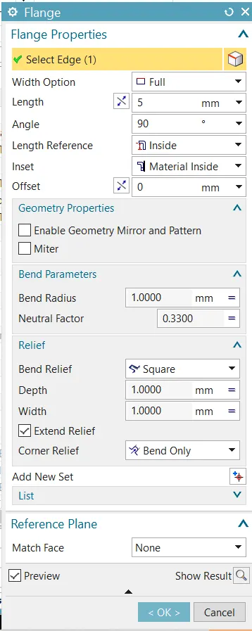
Flanges: This command to add a flat flange at an angle to a planar face and add a bend between the two. A flange consists of a bend region and web. In the flange properties we have to select the edge where we want to create the flange , then length of the flange is given, direction and angle of the flange is set to complete the process.
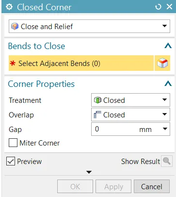
Closed Corner : This command used to modify two flanges in one operation and to close the corner where the two flanges meet. During flattening, the corner and relief geometry are made appropriate for a flat pattern.
- Mitered closed corner with smooth transition from miter to the cutout edges for the circular cutout, U cutout, V cutout, or Rectangular Cutout type of corner treatment options.
- This smooth transition ensures that any jerks or jitters while tracing the tool path are avoided.
Hem Flange : This command is used to modify an edge of a sheet metal part by folding it onto itself for the purpose of safe handling or to increase edge stiffness. The Hem Flange is always created as a secondary feature on the base part.
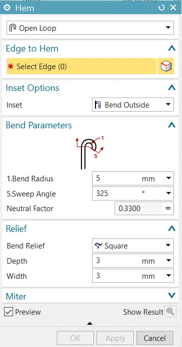
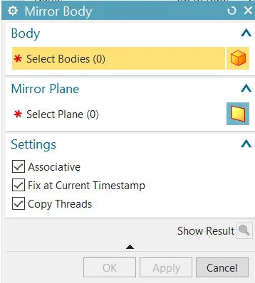
Mirror Body : This feature is selected to mirror the whole body about a particular plane or axis. In order to use this feature we have to select the sketch and body we want to mirror and we have to specify the plane about which we want to create the mirror.
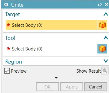
Unite : This feature combines the volume of two or more solid bodies into a single body.In order to use this feature we have to select the target body which we want to combine with the tool body.
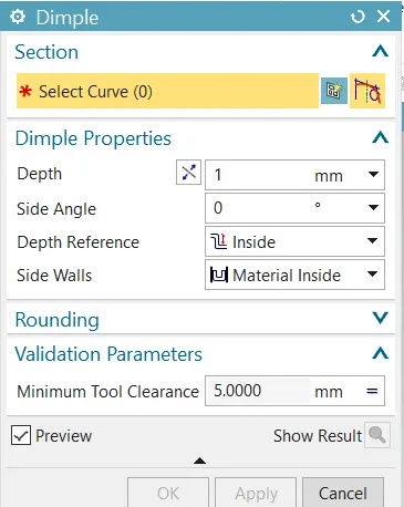
Dimple: This feature lifts the area of the model inside the sketch to simulate a stamping tool. In this feature first the sketch is selected whose shape will behave as the shape of the stamping tool then depth, side angle are given and accordingly depth reference and side walls are selected to get the desired stamping and lastly minimum tool clearance is given.
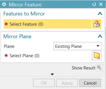
Mirror Features: This feature is selected to mirror only the features about a particular plane or axis. In order to use this feature we have to select the sketch and feature we want to mirror and we have to specify the plane about which we want to create the mirror.
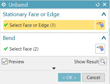
Unbend: This feature flattens a bend and the material adjacent to bend. In this we first have to select the stationary face or edge and the face we want to unbend is selected.
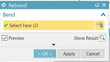
Rebend: This feature restores the unbend feature to its previous bent state, along with any feature added after the unbend feature. Here the unbend face is selected to return it to its original state.
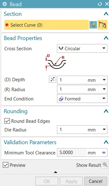
Bead: This feature lifts the material along the contour of the sketch that simulates a stamping tool. In this feature sketch is selected followed by the cross section type which can be circular, U shaped, and V shaped then the depth and radius of the cross section is selected, then we can select the “round bead edges” option followed giving the parameter of minimum tool clearance.
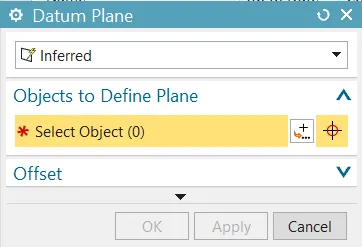
Datum Plane : This feature is used to create a plane at a desired location. We first have to the select the object to define the plane and then distance is given if required.
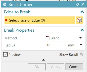
Break Corner : This command is used to round or chamfer sharp corners of a tab or a flange, this done to reduce stress at the sharp edges. In order to use this command first the “Method” is given which can be “Chamfer” or “Blend” and then the radius is inserted to complete the step.
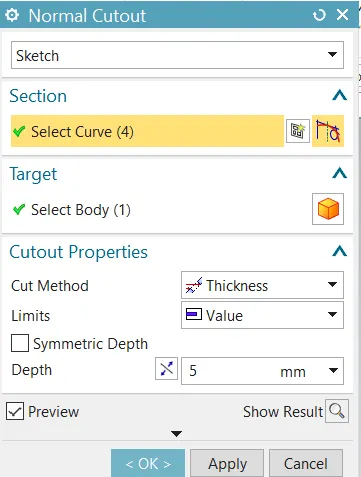
Normal Cutout : This feature is used to cut the material by projecting the sketch onto the model and then cutting perpendicular to faces intersected by the projection. In order to use this command select the curve or sketch to extract, then if there is a problem with the cutout sketch, change options of “Limits” or “Cut Method” in the “Cutout Properties” tab and click “ok”.
Model images :
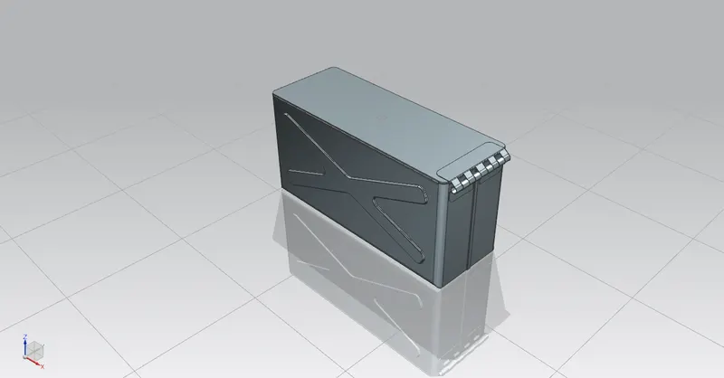
ISOMETRIC VIEW
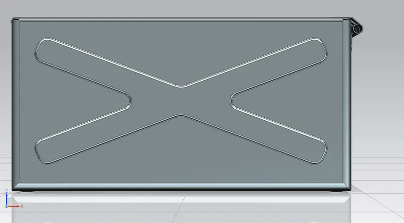
SIDE VIEW
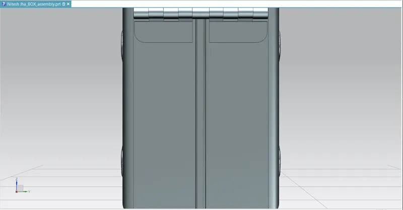
BACK VIEW
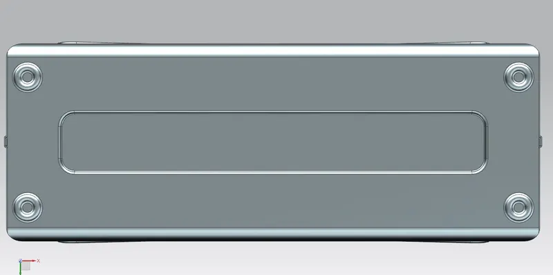
BOTTOM VIEW
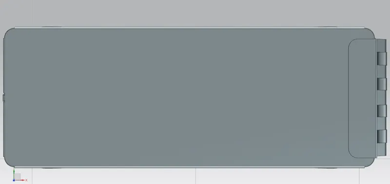
TOP VIEW
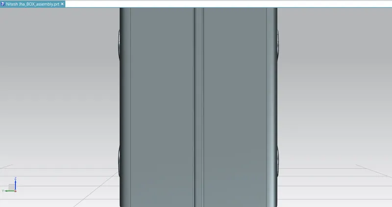
FRONT VIEW
Conclusion :
- While creating dimple care should be taken, on which side the dimple is created and accordingly the sketch should be created so that the dimple is created on the right side.
- The rebending of the model should be done in just the reverse order of the unbending.
- In the “Mirror Features” command the sketch as well as the feature is to be selected in order to mirror the whole feature about a certain plane or line.
- The Mirror feature and Mirror body helps to reduce extra work, if the body is symmetric or the same feature is to be done.