Radar Mast & Final Assembly of Yacht
Design of a Yacht using Solidworks
Objective
Have we ever wondered how these giant machines like ships, airplanes, construction equipment are made? Do these machines be made directly to the factory without any plans, without any blueprints, without thinking? But the answer will be no. In this world, everything from a needle to large airplanes, everything requires a design. Every machine, equipment, and everything around us is made up of our thinking, which we may have made on a piece of paper at some point in the past. Can we really make our imagination on paper? Can we present our thoughts about these types of giant machines to anyone with the right size, right color, and right material on a piece of paper? We can never give up our thinking completely on a piece of paper. But we have the option to present our ideas properly and we can present our imagination to the world through software i.e. SolidWorks. Through this, we can make anything from small to big and change our thinking into reality.
SolidWorks was invented by Dassault Systems. It is a CAD (computer-aided design) / CAM (computer-aided manufacturing) / CAE (computer-aided engineering), associative software used worldwide to create 3D models, design, and drawings.
- Here our objectives will be to create a model from scratch to end.
- We will design different parts of our model and assemble them to create a mule of the product by giving proper shape, size, and color.
Introduction
Now we will create and assemble a complete model of a Yacht using Solidwork software.
Solidworks has divided into 3 parts:-
- Part Modeling
- Assembly
- Drawing
Part Modeling
In the part modeling area, we will create a model by using different drawing tools provided by the software.
In part modeling, there are so many tools and interfaces are used.
- Surface Modeling
- Solid Modeling
Surface Modeling
Surface modeling is an important design platform in Solidworks. Here the design we create doesn't contain any mass property. Here we can create the most difficult design having any dimension, any curvature, and any shape. After giving the final touch to our imaginary project/design, we can convert that model to a solid-state.
After creating the surface design into solid, we can give proper shape, size, dimension, material to it.
Before the creation of the model first, we have to choose a proper plane to locate our model. There are 3 planes are used i.e Front Plane, Top Plane & Right Plane.
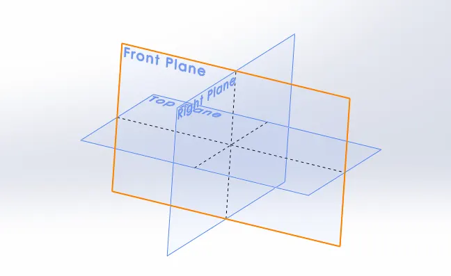
Design Methodology/approach
Part required for the design:-
- Hull
- Propeller
- Garage Door
- Radar Mast
- Radar
- Super Structure
- Front Seat
- Middle Seat
- Rear Seat
Description Of Tools in Surface & Part Modelling used in the design:-
We will discuss the tools we are going to use in the model & then will create the model.
1.Curve
It is a very useful tool in the software. 
With using this tool, we can create a third sketch by using two different sketches of a different dimension, which can be present on any plane.
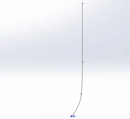
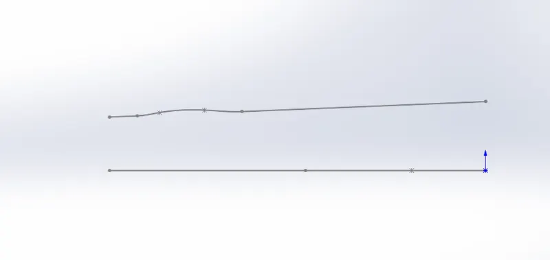
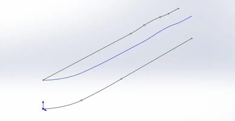
There are two different drawings present in the various planes. The blue line present in the third image is a curve that is formed by selecting the two sketches.
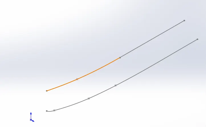
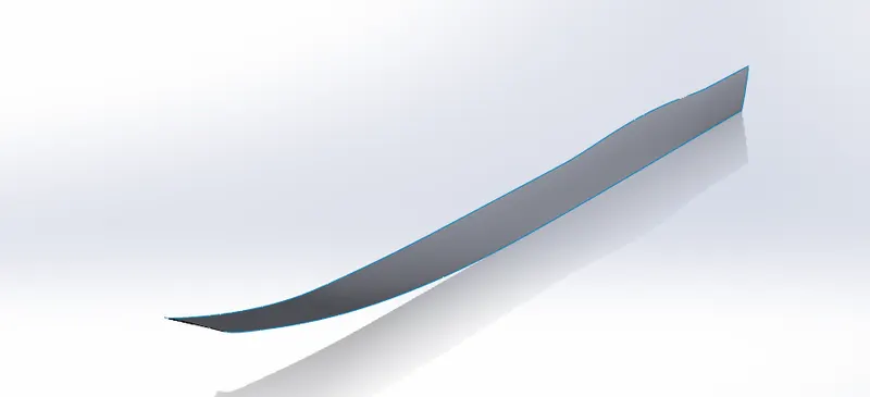
2.Surface Loft
A loft is a tool which is used to add material between two or more profile to create a surface feature.
3.Surface Trim
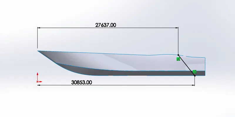
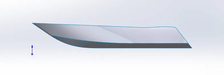
Trim is used to removing material between intersecting parts, planes, or sketches.
4.Surface Extrude
Extrude is used to create a solid/surface feature from a sketch
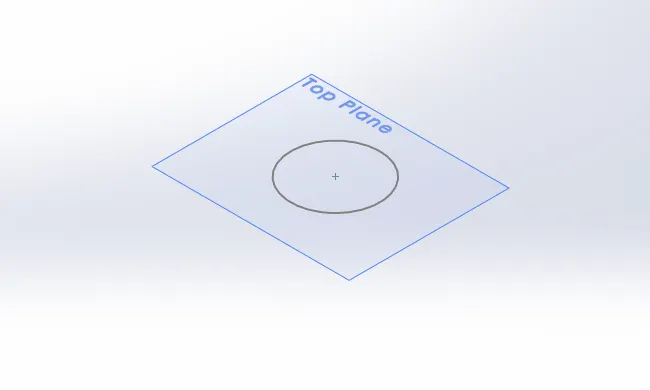
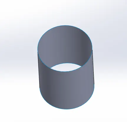
As you can see there is a Surface Extrude created from a sketch i.e present in Top plane.
5.Surface Knit
It is used to combine two or more adjacent non-intersecting surfaces together. This tool is only used in surface modeling.
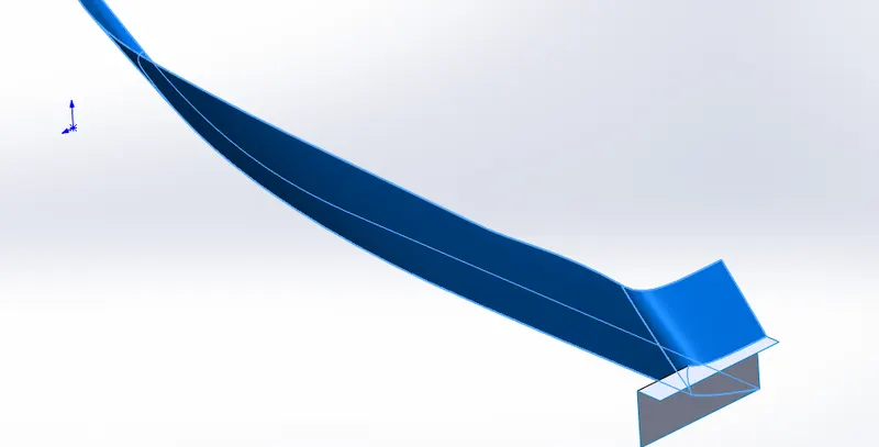
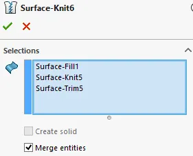
In this sketching tool, we can convert the surface to solid by clicking create solid.
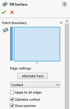
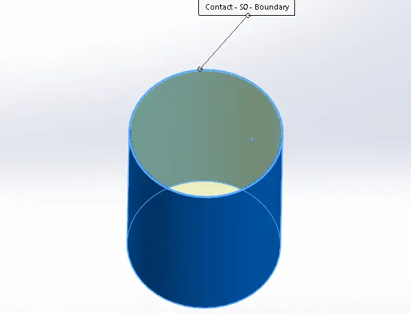
6.Surface Fill
Surface fill is used to create a patch to a boundary by defining edges, sketched, or curves.
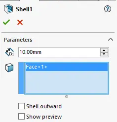
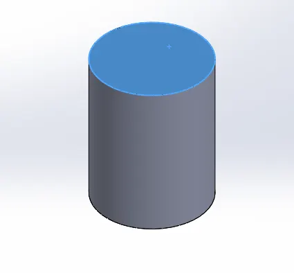
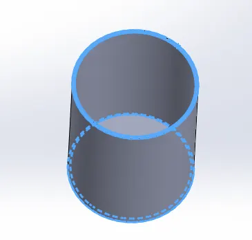
7.Shell
It is used to remove material from a solid body to create a thin wall feature.
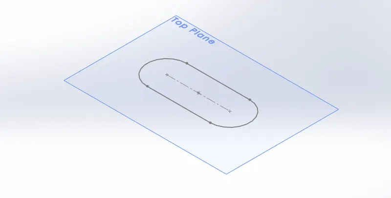
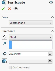
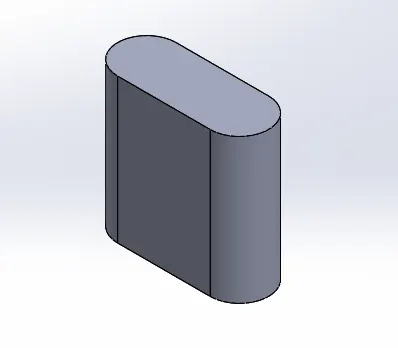
8.Boss Extrude
It is used to create a solid feature.
9.Cut Extrude
It is used to remove material from a solid body/feature.
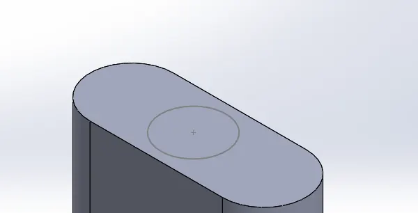
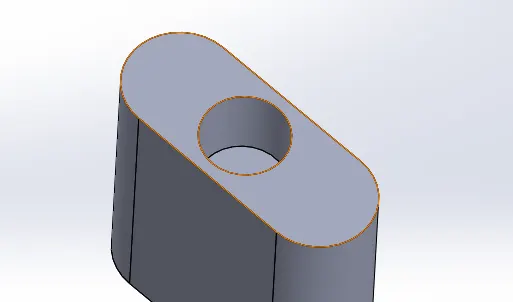
You can see the material is removed from the solid body.
10.Fillet
It is used to create a round face in the edged to avoid sharpness.
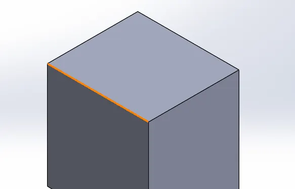
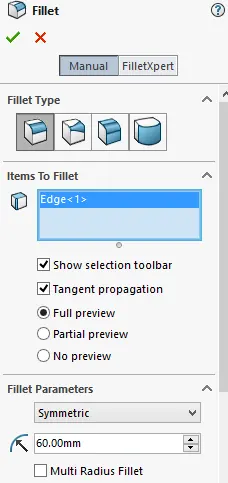
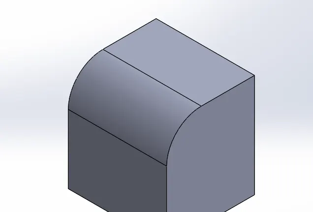
As you can see the fillet has been applied to the edges.
11.Chamfer
It is used to create a flat surface in the corner vertex, edges of a solid body.
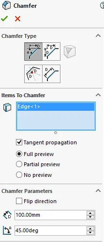
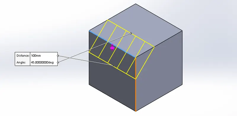
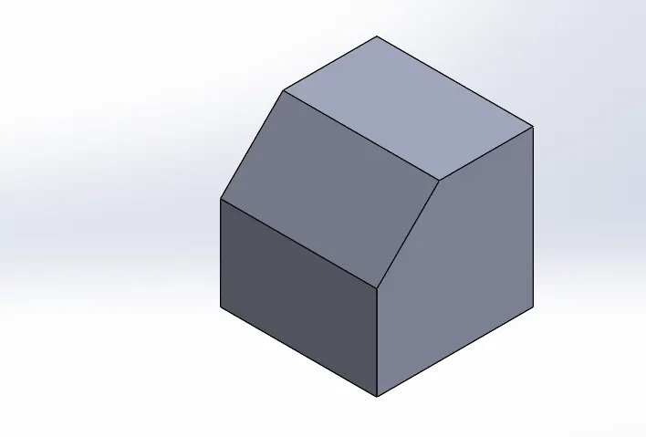
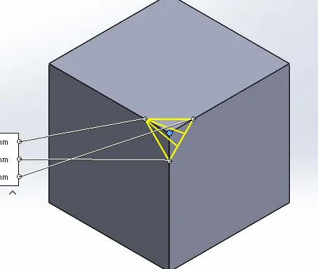
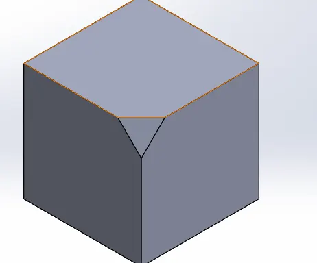
As you can see the chamfer has been applied to the edge and vertex of the solid body.
There are different types of chamfer which we can select from chamfer type which consist Distance-Distance chamfer, Distance-Angle Chamfer, Vertex Chamfer, Face-Face Chamfer, Offset Face Chamfer.
12.Sweep
It is used to create solid by creating two different sketches in the different planes as sketch and path.
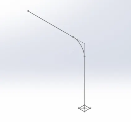
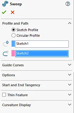
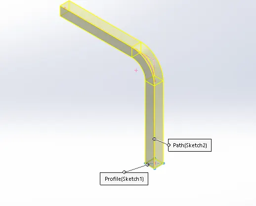
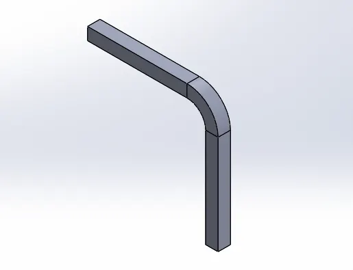
In the 1st image, you can see we have created two different sketches in different planes like the top plane and the right plane. After that, the sketch adjacently selected as path & profile, and the sweep has been created.
13.Revolve
It is used to create any solid body in a circular path.
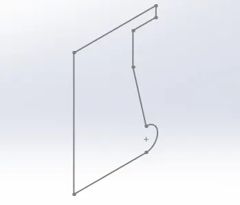
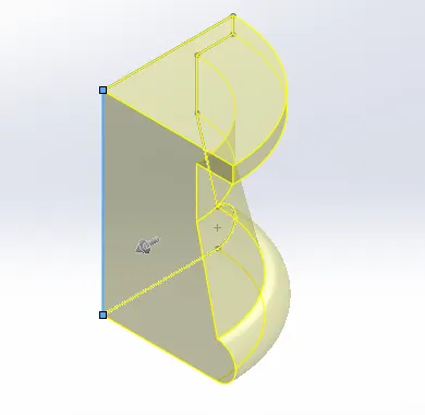
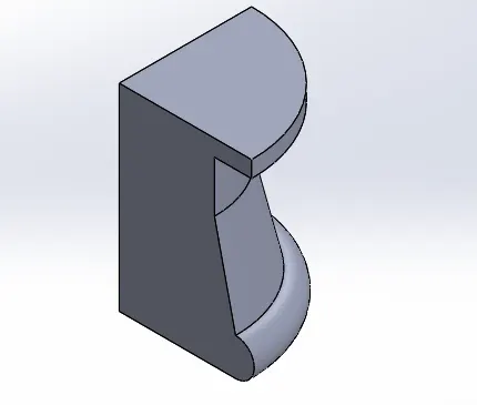
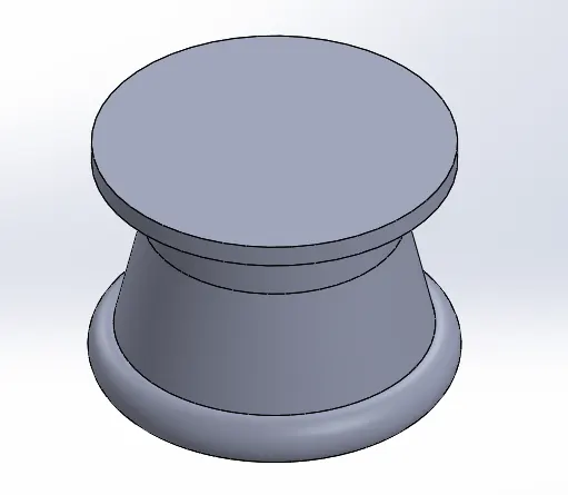
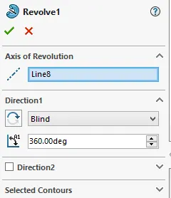
As you can see we have created a profile in the right plane and selected the selected blue line as the axis of revolution and the profile has been created, Here we can control the revolving angle as per our requirement.
14.Mirror
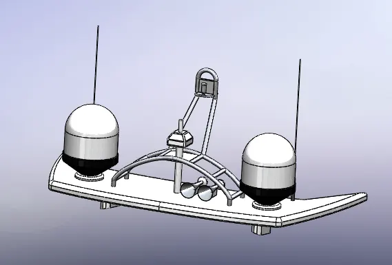
The mirror is used to create the same features, bodies about a face & plane.
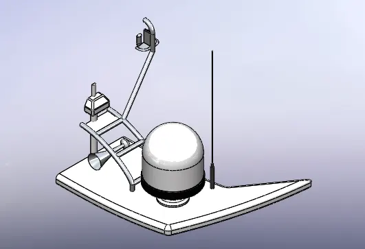
As in the above image, the design is present in half. But we can mirror the other parts of a plane.
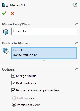
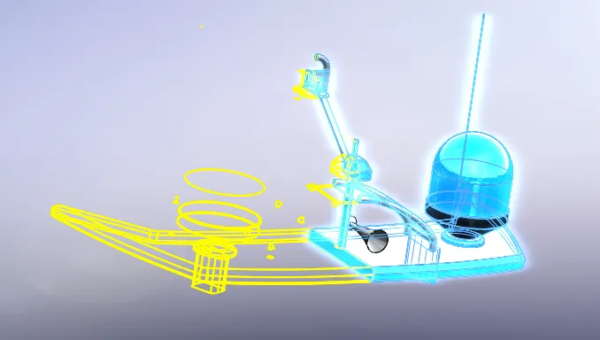
As we can see when we mirroring our image ita creates a preview of the face.
15.LINER PATTERN
The pattern is used to create the feature in multiple numbers in a row or column.
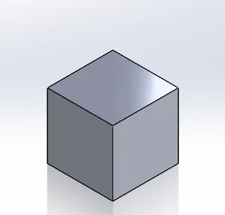
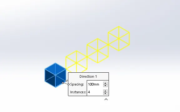
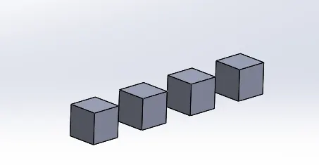
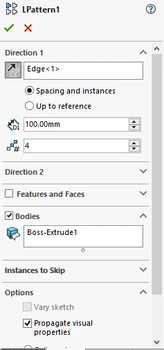
As we can see the bodies have been created in multiple numbers in a row. Like that, we can create in the column also.
16.SURFACE EXTEND
Surface extends is used to extend the edges of the surface to a limit.
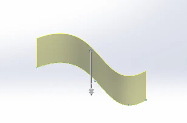
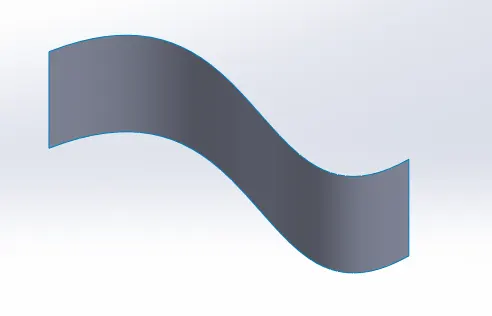
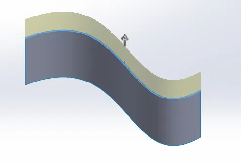
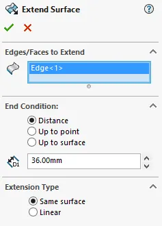
As we can see after creating a surface extrude when we are selecting edges of the feature it gets extended as per our given dimension.
17. SKETCH TOOLS
After selecting the planes we have to create a drawing. So there are different drawing tools like
- Line

- Spline

- Rectangle

- Circle

- Slot

- Ellipse

- Polygon

- Arc

- Point
Some drawing editing tools like
- Trim Entities

- Convert Entities

- Offset Entities

- Mirror Entities

- Liner Sketch Pattern

- Circular Sketch Pattern

- Move Entities
- Copy Entities
- Scale Entities

- Rotate Entities

DESIGNING OF DIFFERENT PARTS WITH TOOLS.
(A) HULL
In this model we have used different tools:-
- Curve
- Sweep Surface
- Lofted Surface
- Trim Surface
- Knit Surface
- Surface Fill
- Shell
- Fillet
- Chamfer
- Cut Extrude
- Boss Extrude
- Seep Boss/Base
- Revolve
- Dome
- Helix
- Mirror
- Linear Pattern
- 3D Sketch
- Surface Offset
Different views of Hull
ISOMETRIC VIEW
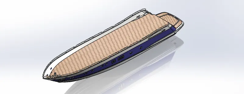
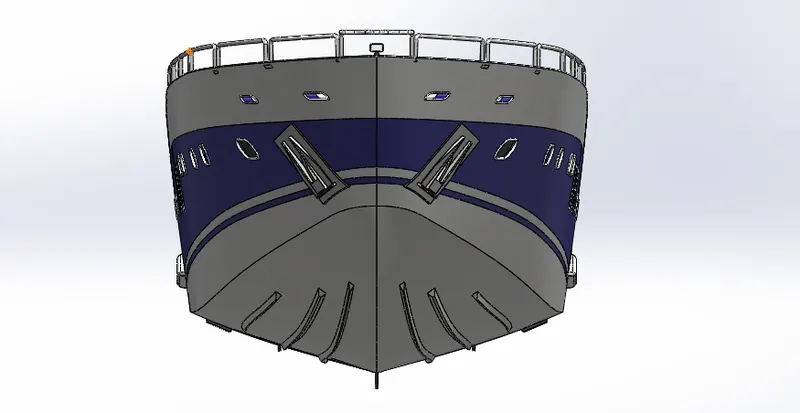
FRONT SIDE VIEW
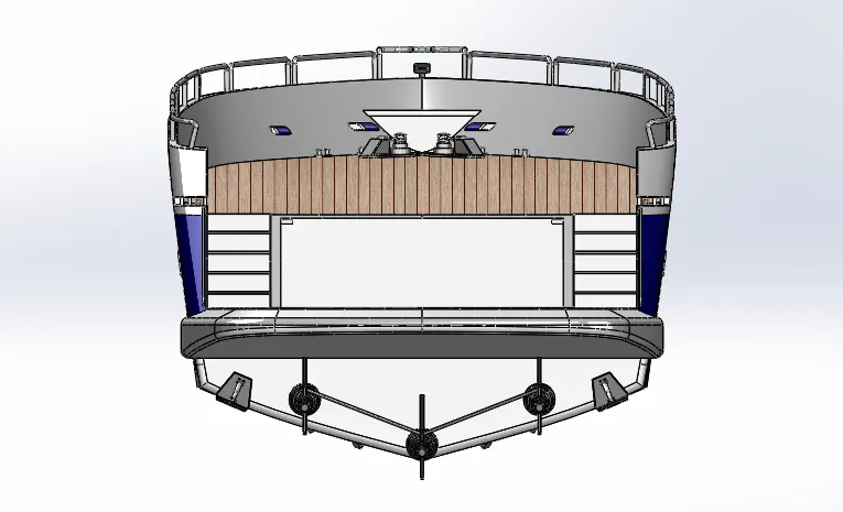
BACKSIDE VIEW
LEFT SIDE VIEW
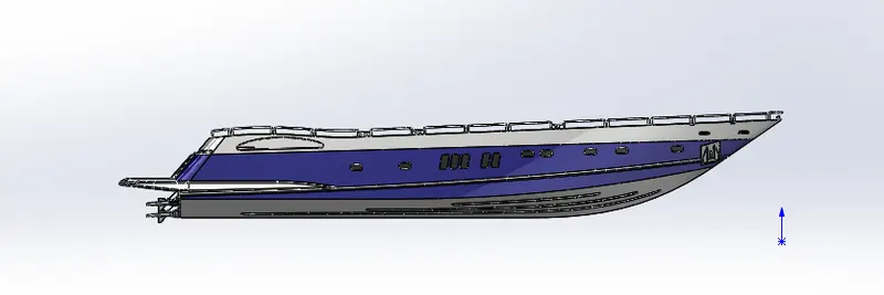
RIGHT SIDE VIEW
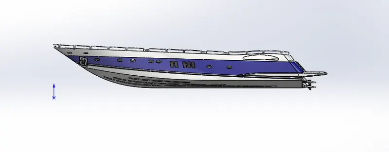
TOP VIEW
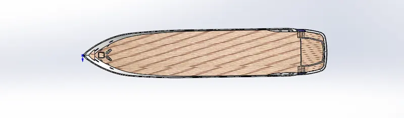
BOTTOM VIEW
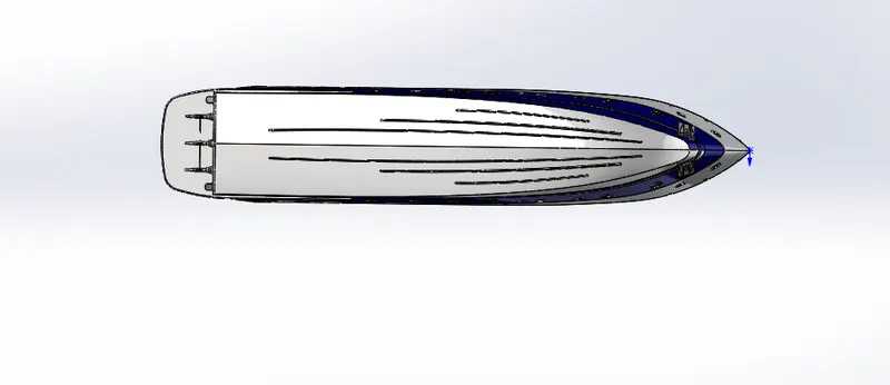
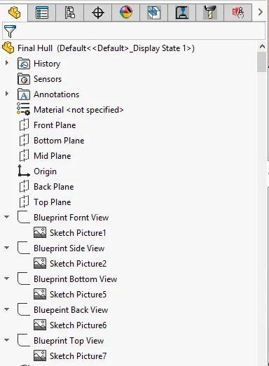
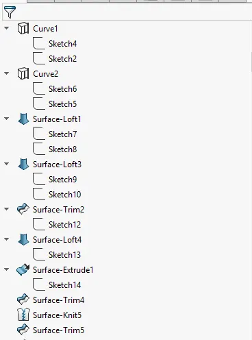
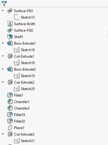
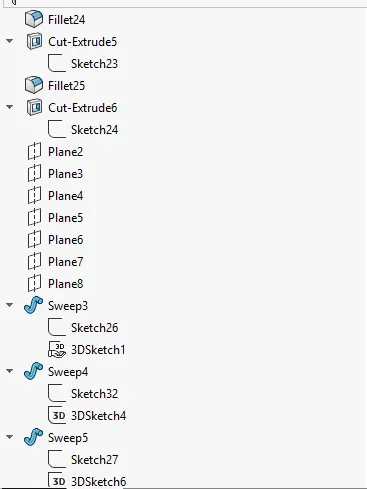
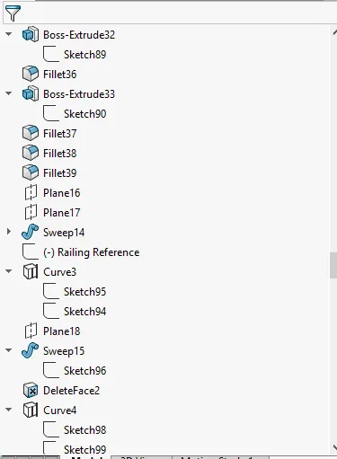
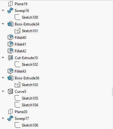
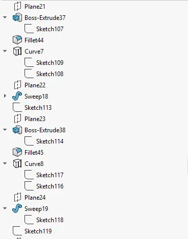
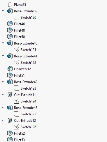
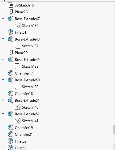
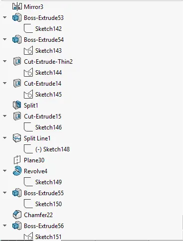
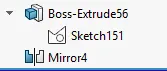
Tools used to approach this model/Feature tree of the hull
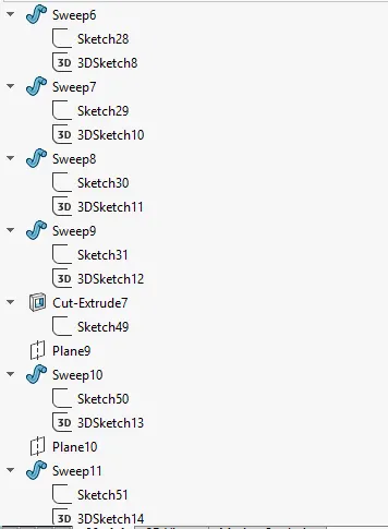
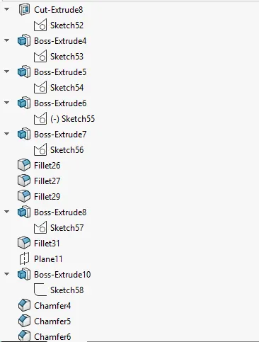
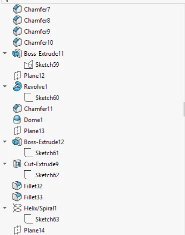
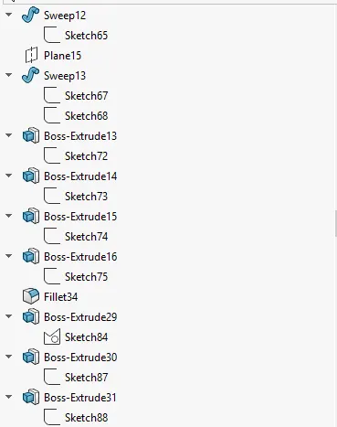
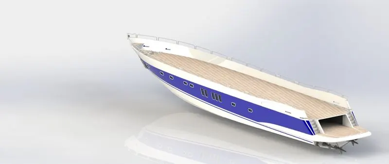
Rendering view of the HULL
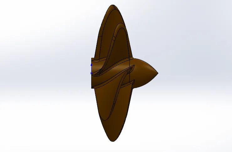
(B) PROPELLER
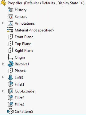
In this model, we have used different tools like
- Revolve
- Loft
- Fillet
- Cut Extrude
- Circular Pattern
Different views of Propeller
ISOMETRIC VIEW
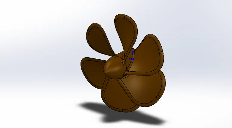
FRONT SIDE VIEW
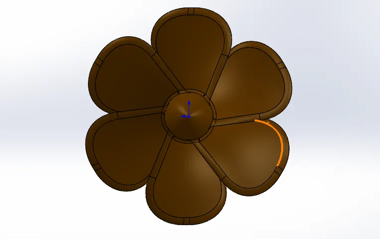
LEFT SIDE VIEW
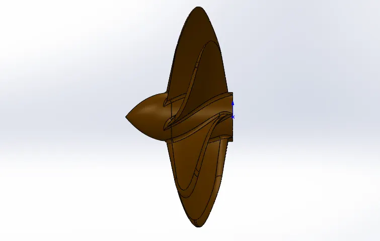
RIGHT SIDE VIEW
Tools used to approach this model/Feature tree of the Propeller
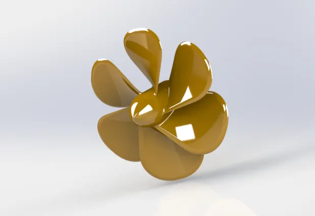
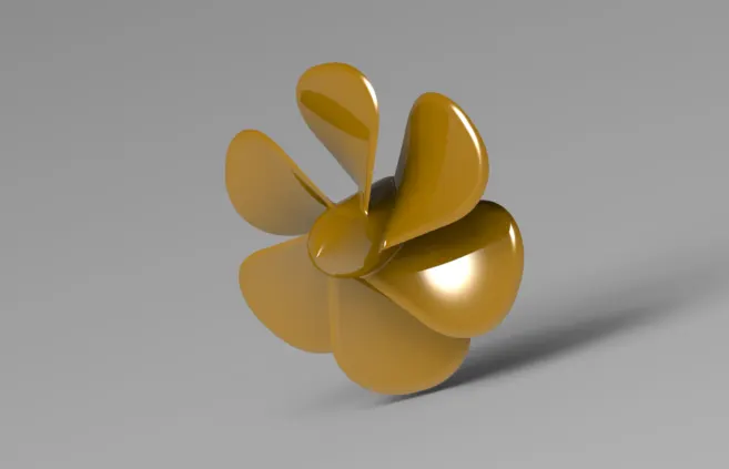
RENDER VIEW OF PROPELLER
(C) GARAGE DOOR
Tools we have used in Garage Door
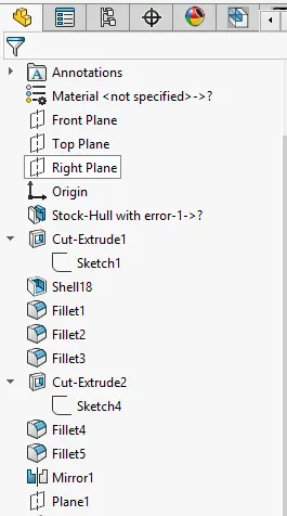
- Cut Extrude
- Shell
- Fillet
- Mirror
Different views of Garage Door
ISOMETRIC VIEW
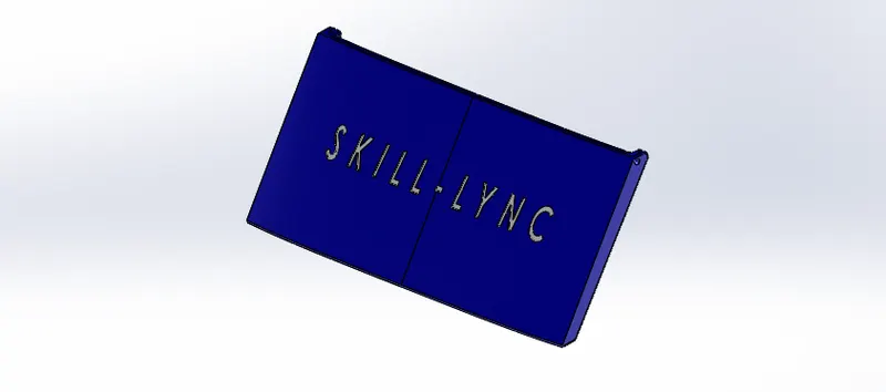
FRONT SIDE VIEW
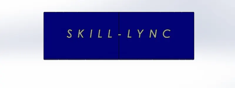
BACKSIDE VIEW
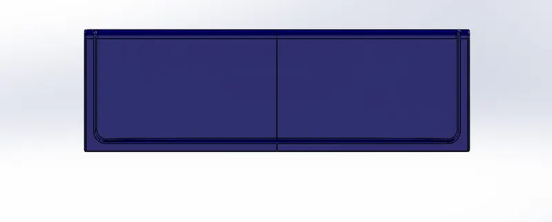
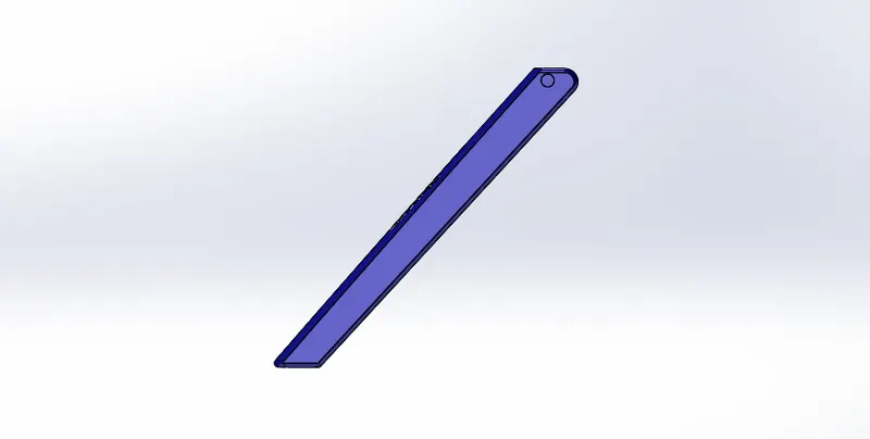
TOP VIEW
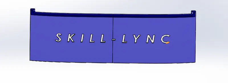
BOTTOM VIEW
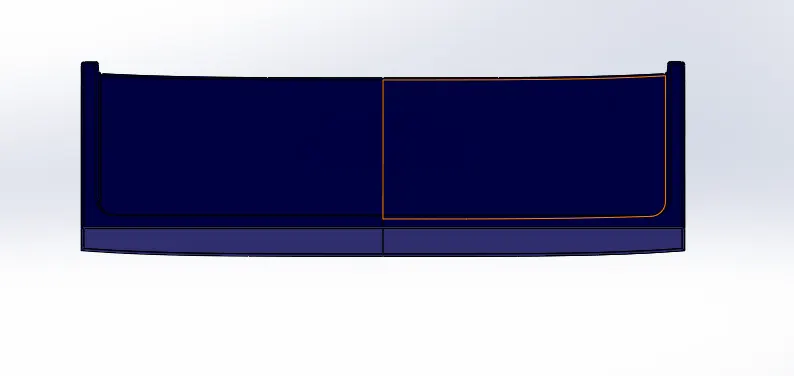
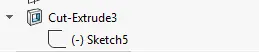
Tools used to approach this model/Feature tree of the Garage Door.
RENDER IMAGE OF THE GARAGE DOOR
(D) RADAR MAST
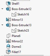
Tools we have used in Radar Mast
- Boss Extrude
- Plane
- Revolve
- Fillet
- Sweep
- Mirror
- Curve
- Dome
Different views of Radar Mast
ISOMETRIC VIEW
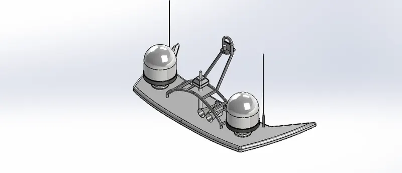
FRONT VIEW
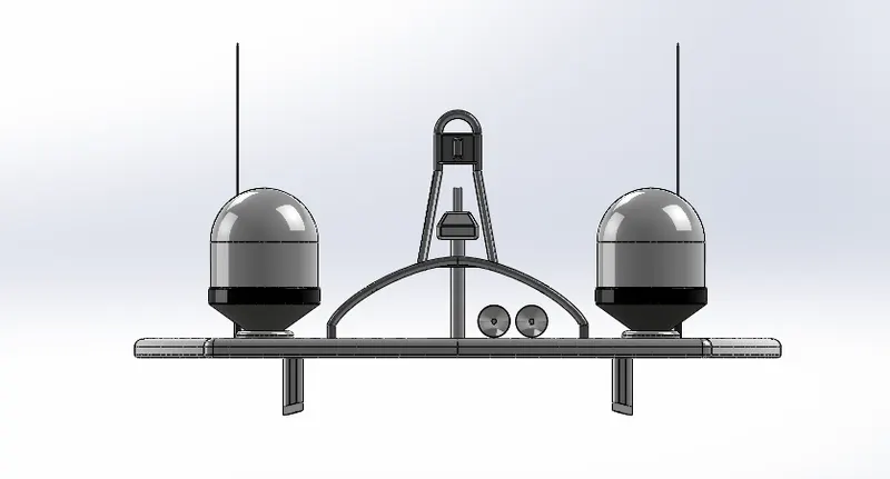
BACK VIEW
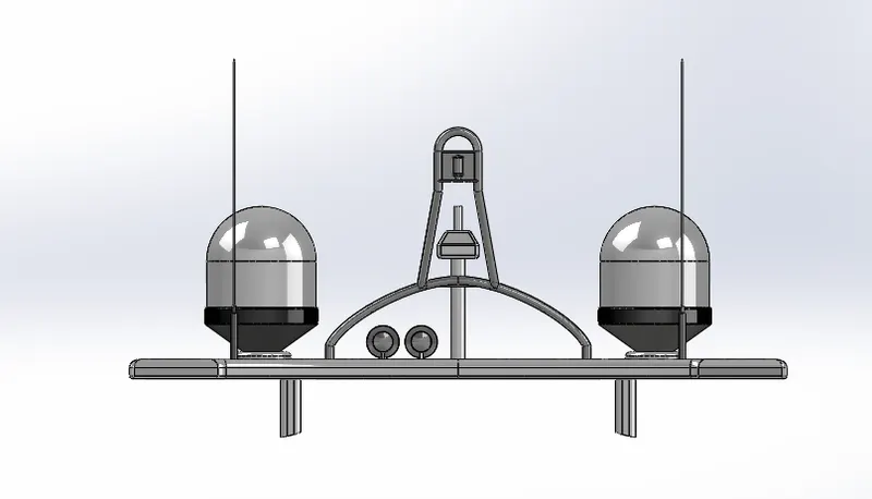
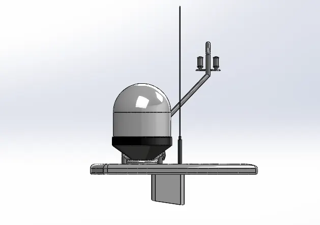
LEFT SIDE VIEW
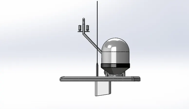
RIGHT SIDE VIEW
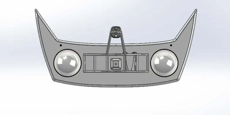
TOP VIEW
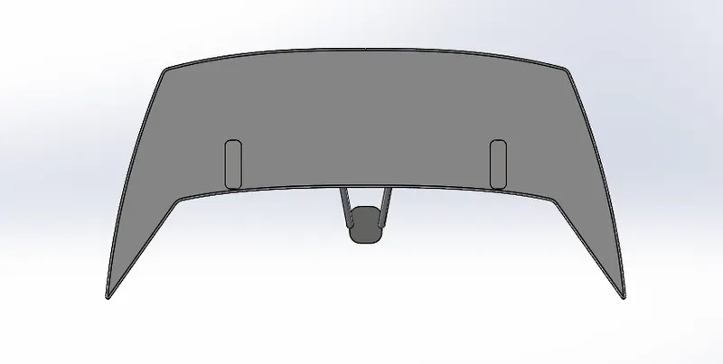
BOTTOM VIEW
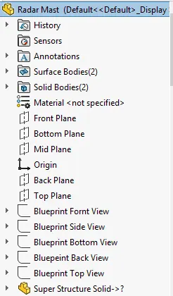
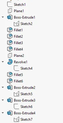
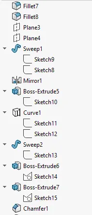
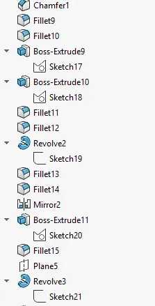
Tools used to approach this model/Feature tree of the Radar Mast
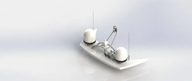
RENDER IMAGE OF THE RADAR MAST
(E) RADAR
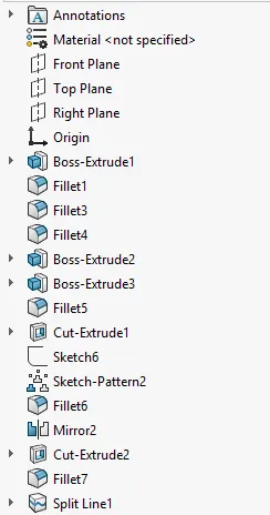
Tools we have used in Radar
- Boss Extrude
- Cut Extrude
- Fillet
- Sketch Pattern
- Mirror
- Split line
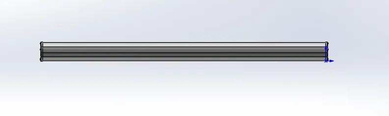
Different views of Radar
ISOMETRIC VIEWS
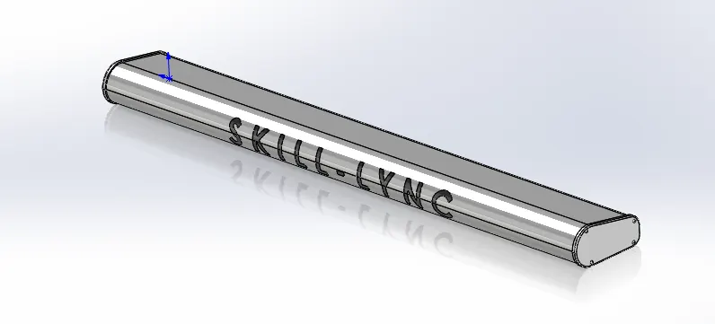
FRONT VIEW
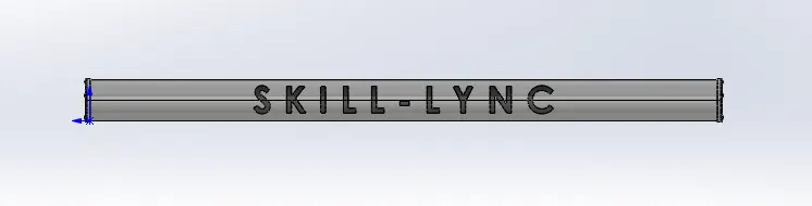
BACK VIEW
Tools used to approach this model/Feature tree of the Radar
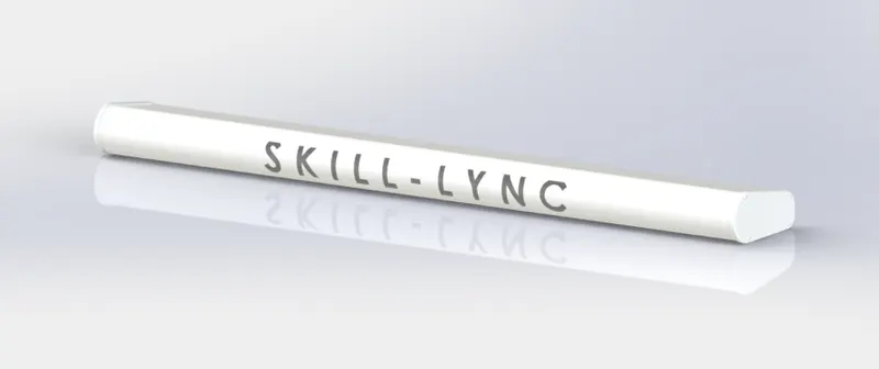
RENDER IMAGE OF THE RADAR
(F) SUPERSTRUCTURE
Tools we have used in Superstructure
- Curve
- Ruled Surface
- Extend SUrface
- Split Line
- Surface Sweep
- Surface Loft
- Surface Knit
- Trim Surface
- 3D Sketch
- Boss Extrude
- Cut Extrude
- Plane
- Revolve
- Thicken
- Dome
- Fillet
- Chamfer
Different views of the superstructure
ISOMETRIC VIEW
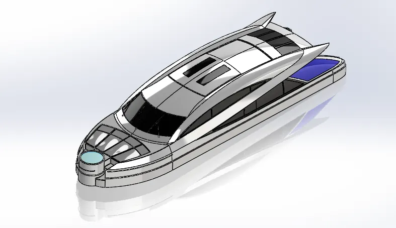
FRONT VIEW
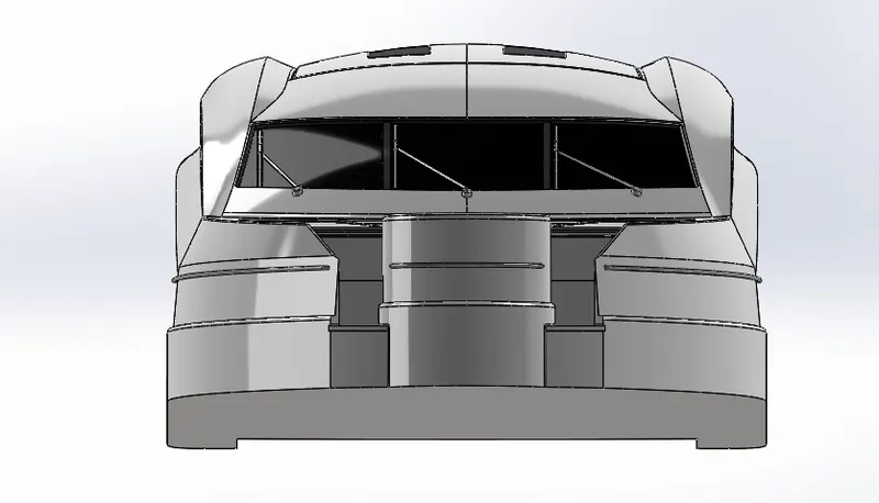
BACKSIDE VIEW
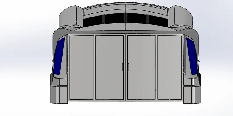
LEFT SIDE VIEW
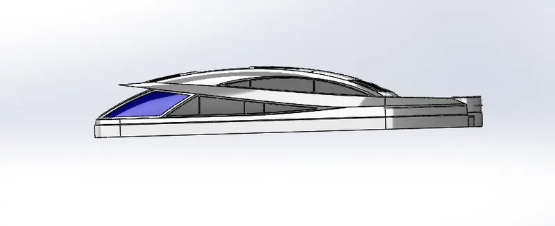
RIGHT SIDE VIEW
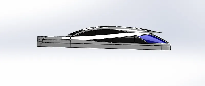
TOP VIEW
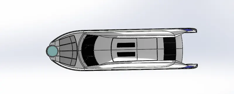
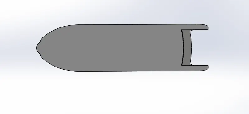
BOTTOM VIEW
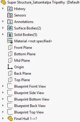
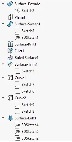
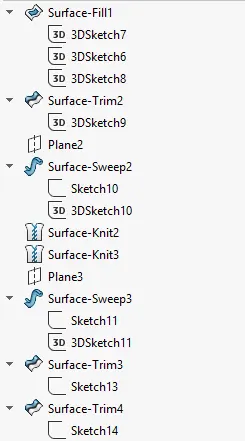
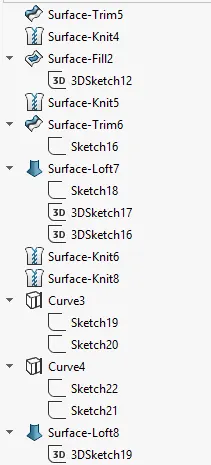
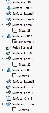
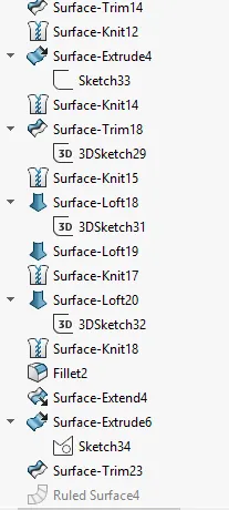
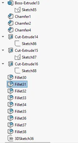
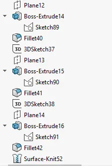
Tools used to approach this model/Feature tree of the SUPERSTRUCTURE
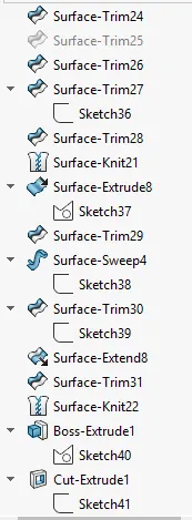
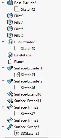
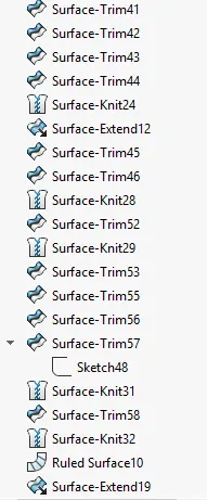
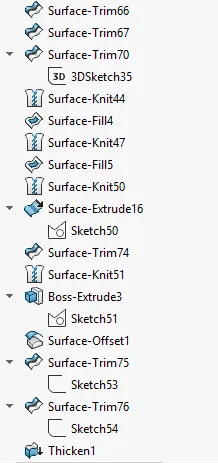
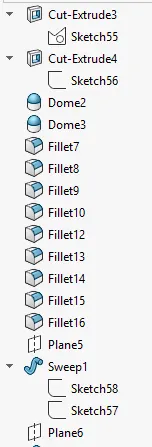
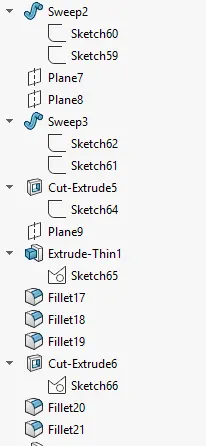
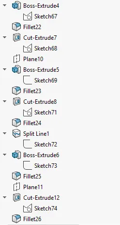
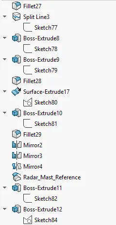
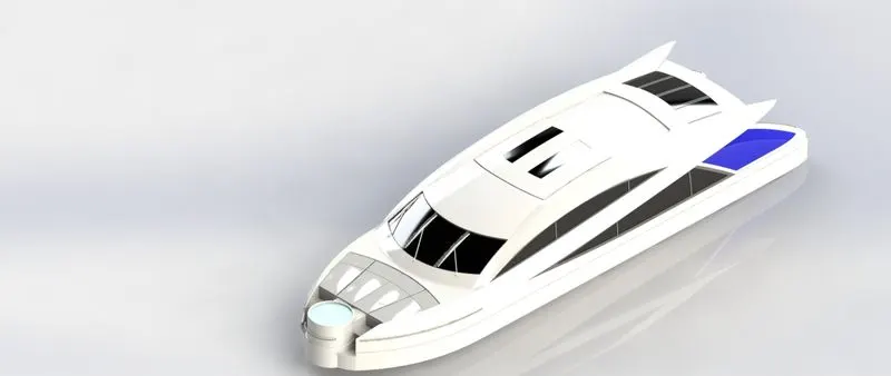
RENDER IMAGE OF THE SUPERSTRUCTURE

(G) FRONT SEAT
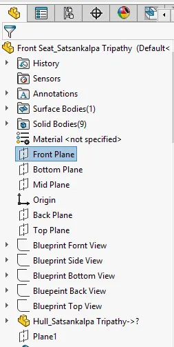
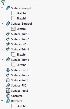
Tools we have used in the front seat
- Surface Sweep
- Surface Trim
- Surface extrude
- Surface Loft
- Plane
- Surface Knit
- Chamfer
- Revolve
- Mirror
- Dome
Different views of Front seat
ISOMETRIC VIEW
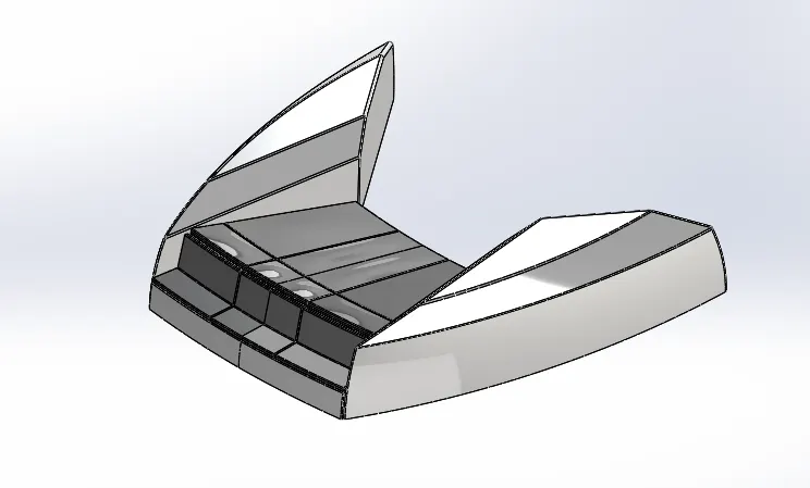
FRONT VIEW
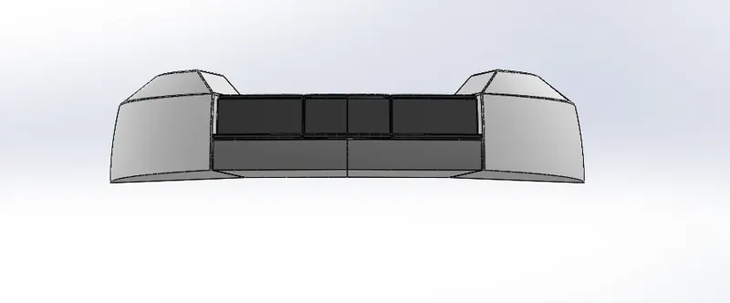
BACK VIEW
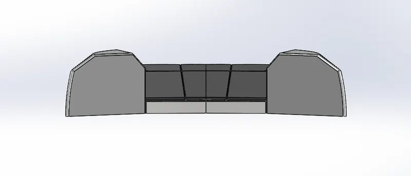
RIGHT SIDE VIEW
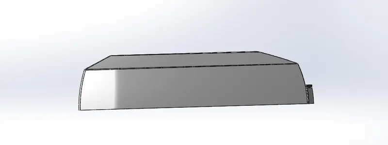
LEFT SIDE VIEW
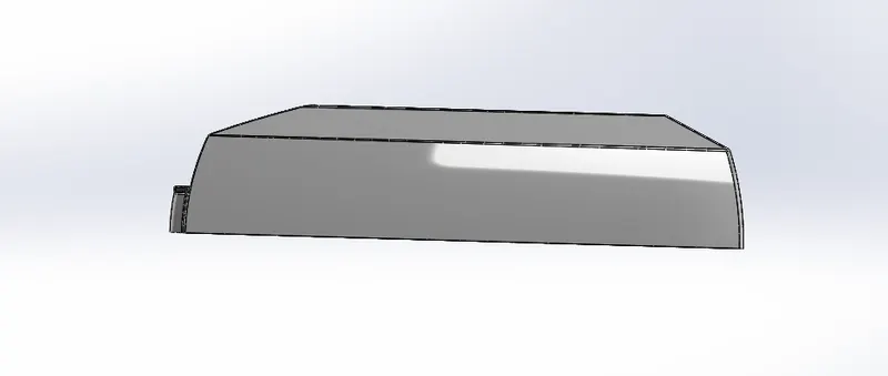
TOP VIEW
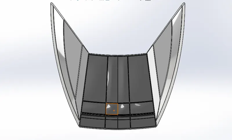
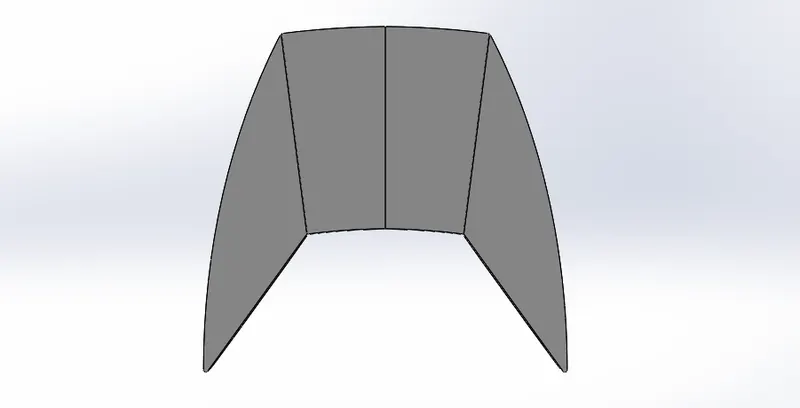
BOTTOM SIDE VIEW
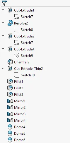
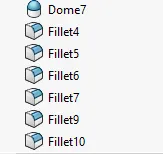
Tools used to approach this model/Feature tree of the FRONT SEAT
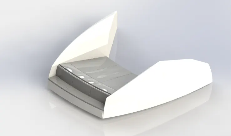
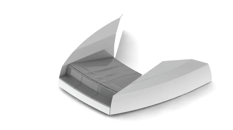
RENDER IMAGE OF THE FRONT SEAT
(H) MIDDLE SEAT
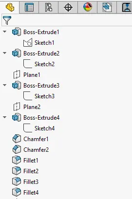
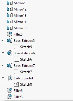
Tools we have used in the Middle Seat
- Boss Extrude
- Cut Extrude
- Chamfer
- Fillet
- Mirror
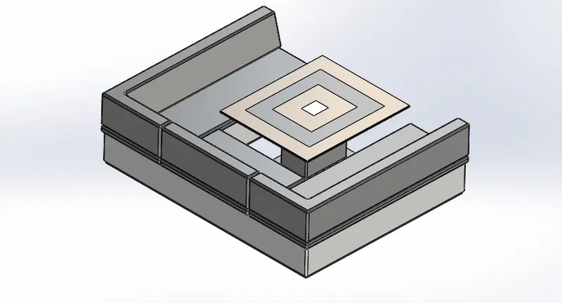
Different views of the middle seat
ISOMETRIC VIEW
FRONT VIEW
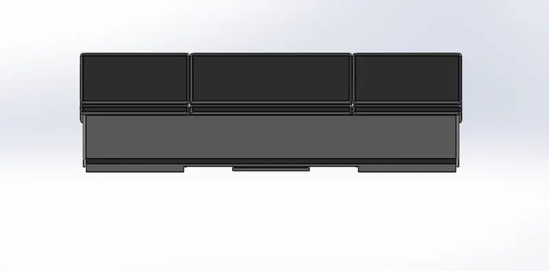
BACK VIEW
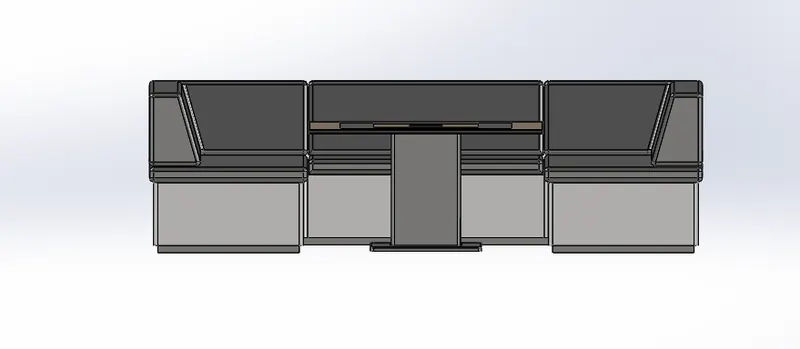
LEFT SIDE VIEW
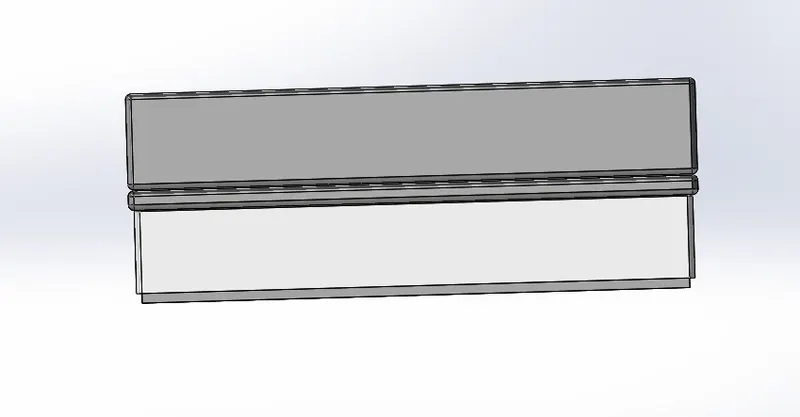
RIGHT SIDE VIEW
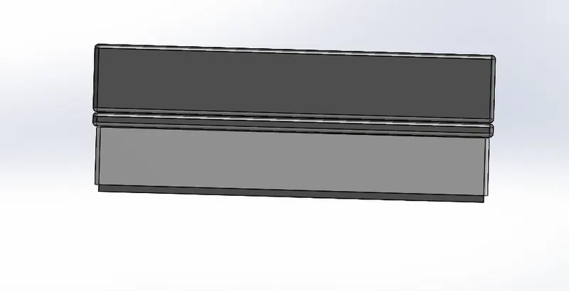
TOP VIEW
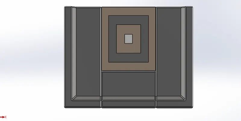
BOTTOM VIEW
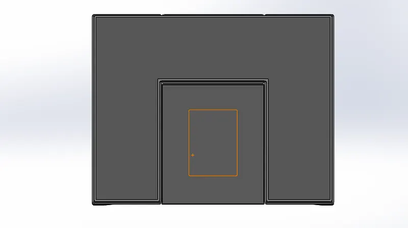
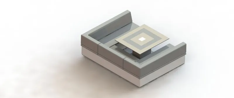
RENDER IMAGE OF THE MIDDLE SEAT
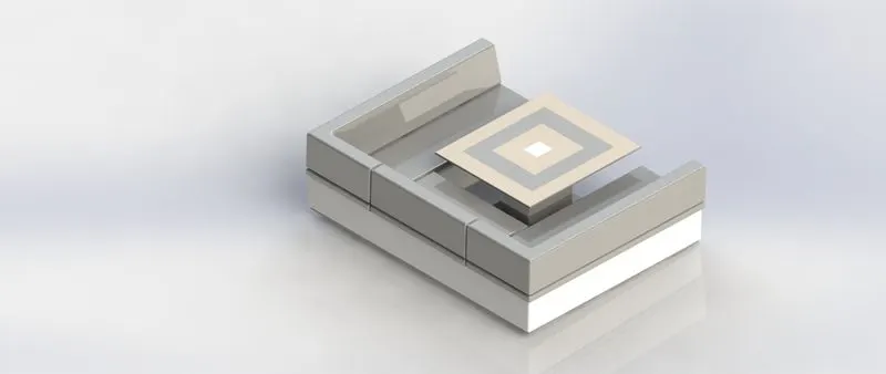
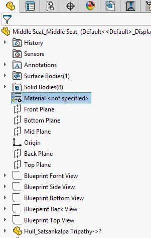
Tools used to approach this model/Feature tree of the MIDDLE SEAT
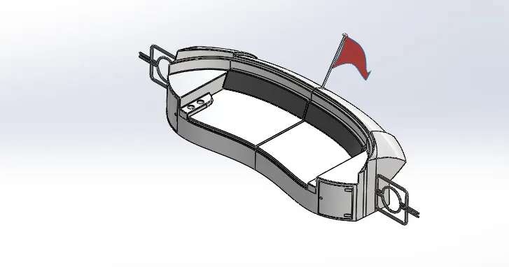
(I) REAR SEAT
Tools we have used in the Rear Seat
- Surface Extrude
- Surface Sweep
- Surface Trim
- Surface Loft
- Surface Extend
- Ruled Surface
- Boss Extrude
- Cut Extrude
- Revolve
- Fillet
- Chamfer
- Sweep
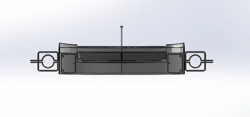
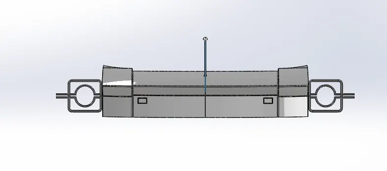
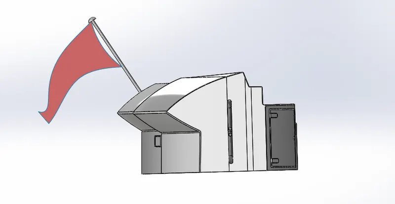
Different views of the rear seat
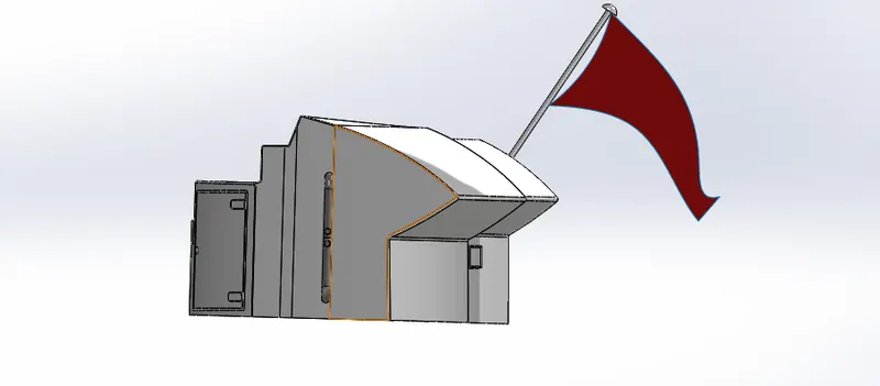
ISOMETRIC VIEW
FRONT VIEW
BACK VIEW
LEFT SIDE VIEW
RIGHT SIDE VIEW
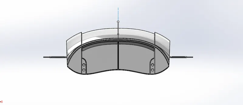
TOP VIEW
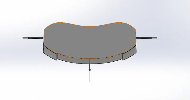
BOTTOM VIEW
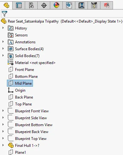
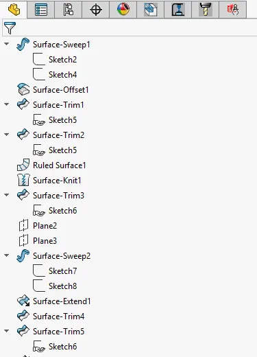
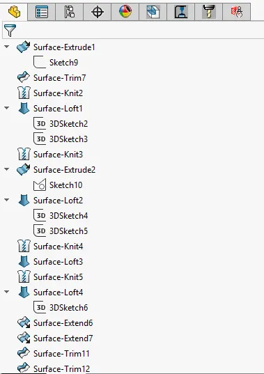
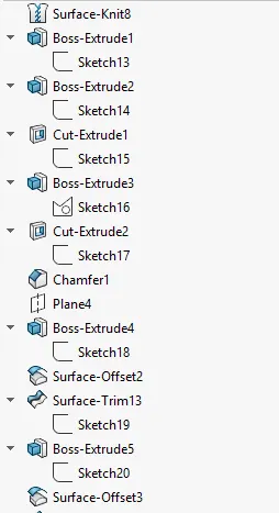
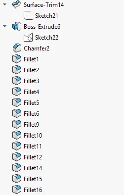
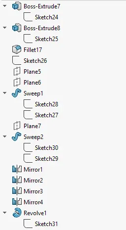
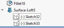
Tools used to approach this model/Feature tree of the rear seat
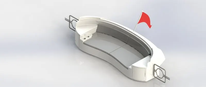
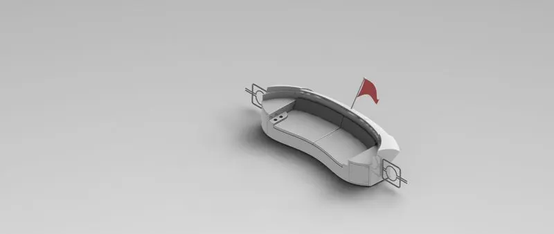
RENDER IMAGE OF THE REAR SEAT
ASSEMBLY MODELING
As Part Modeling is a part of Solidworks, like that second part of the software is Assembly Modeling. Here we will insert our individual components into the assembly area and will assemble them in their place by applying some mates.
Mates is nothing but to make a part fully defined by applying some Geometrical, Dimensional & Mechanical constraints.
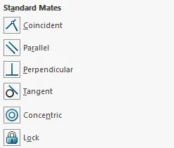
Geometrical Constraints
Geometrical constraints are
- Coincident
- Concentric
- Parallel
- Perpendicular
- Tangent
Dimensional Constraint
Dimensional Constraints are to make a mode fully defined by giving some dimensions.
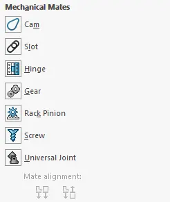
Mechanical Constraints
Mechanical Constraints are
- Cam
- Slot
- Hinges
- Gear
- Rack & Pinion
- Screw
- Universal
Now we will start our assembly modeling.
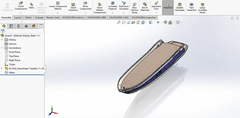
First, we have to insert our base model which is Hull
Click On insert component
Then insert the base model.
Then we will our second model i.e Superstructure.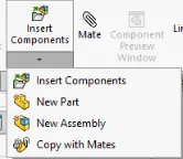
 Click on the model & will click on open
 & after the file gets opened we have to click on the ok button on the feature tree, which will make the superstructure auto constraint over the hull. This will happen as we have been prepared the model by taking the reference of the blueprints.
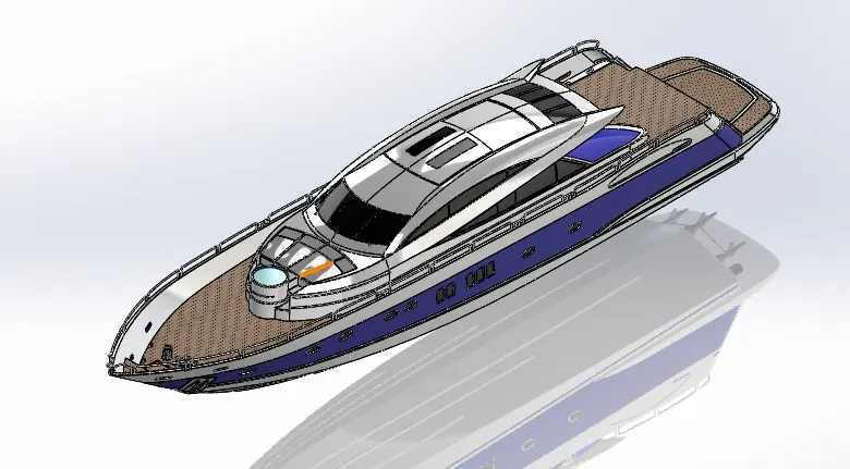
After that we will insert the Front seat, Middle seat & radar mast one by one to the assembly area & all the models will be automatically constraint after clicking ok on the feature tree.
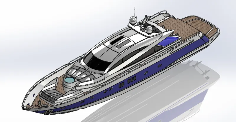
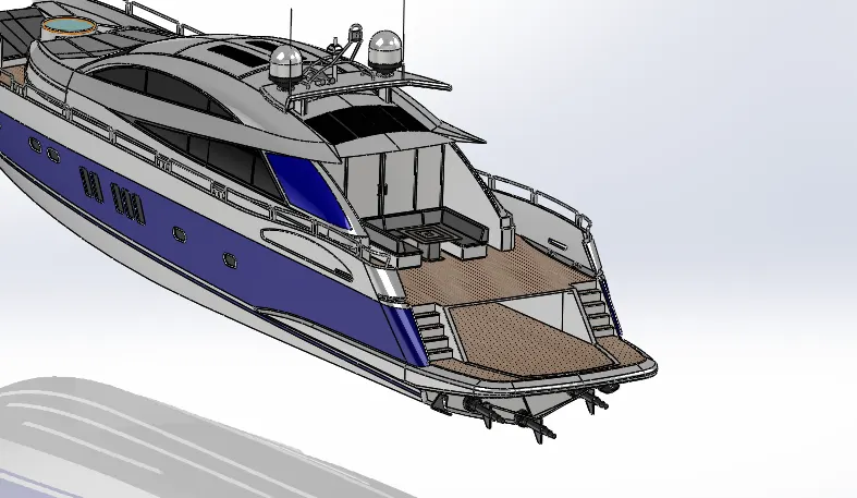
Then we will insert the rear seat and will place that on the assembly sheet by clicking anywhere on the screen.
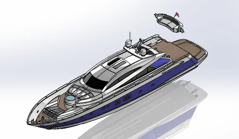
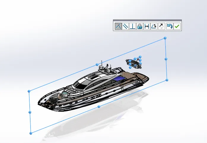
Then we will apply mates between the rear seat and the hull.
The first mate will be between the middle plane of the hull and the middle plane of the rear seat.
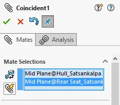
The second mate will be between the deck face of the hull and the bottom face of the rear seat.
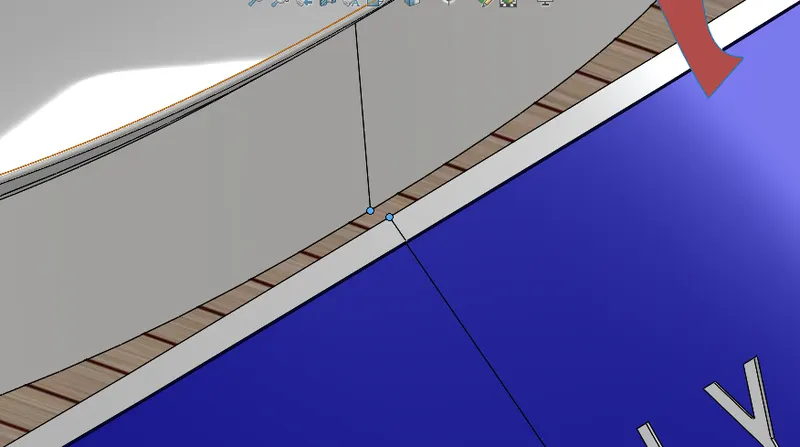
The third mate will be between the showing vertex with a distance of 50mm.
After that, we will insert the garage door and can by clicking on the screen. Here also the mates will be between both the mid planes of the garage door and the hull. The second mate will be between the faces of the garage door and the hull as shown in the picture. It will be automatically concentric. Then click ok.
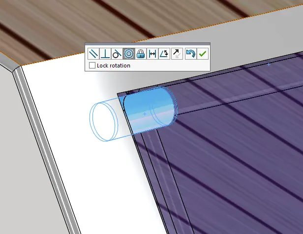
After that, we will insert the propeller. We have to insert three times for 3 parts.
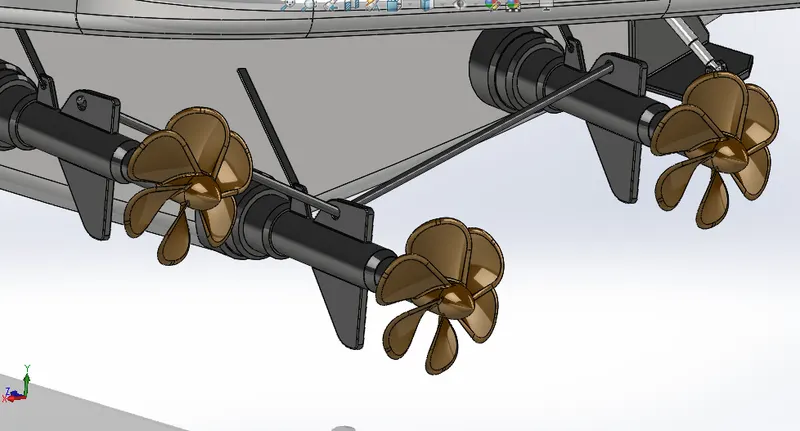
Here the mates will be between the faces of the propeller and the propeller hub.
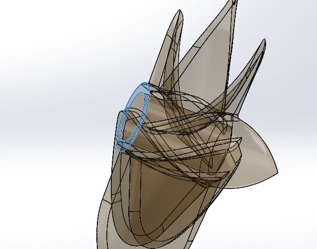
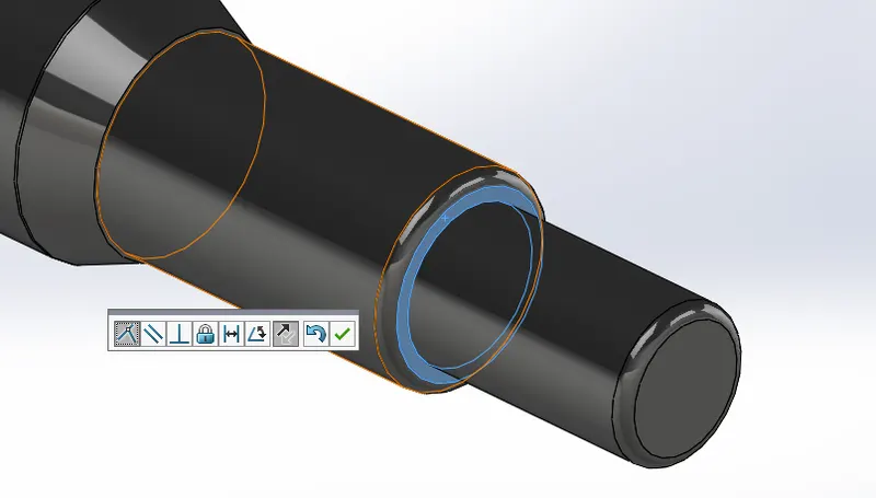
The second mate will be between the blue faces as shown in the image.
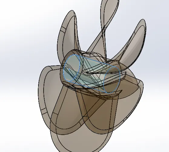
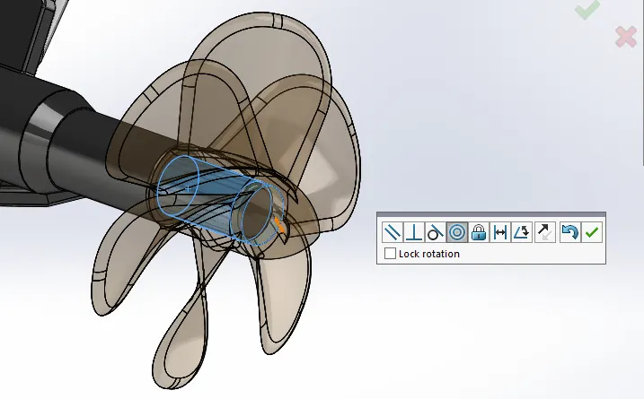
The last component will be the radar. Here the mates will be the same as before we have applied in the propeller.
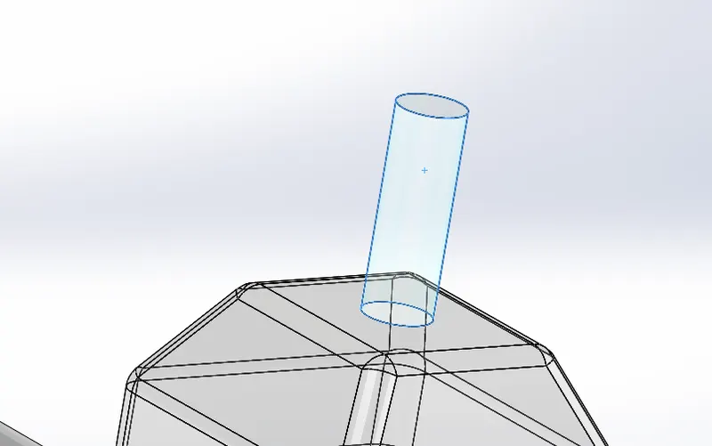
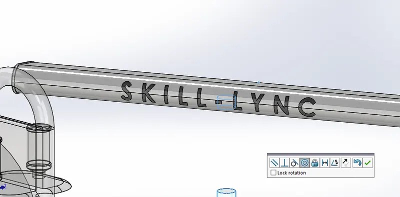
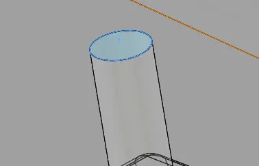
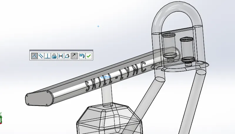
Now our assemble is complete.
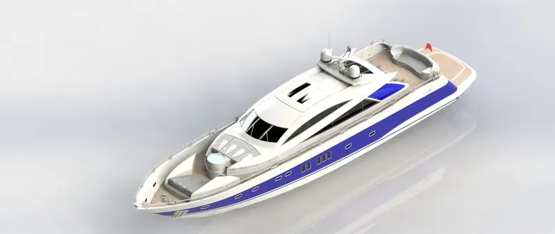
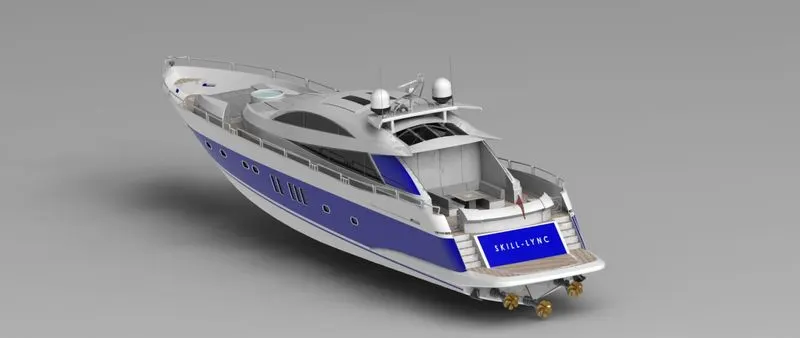
RENDER IMAGE OF THE ASSEMBLY
Conclusion
- In this model, the different parts of the Sunseeker Predator Yacht have been designed separately in the Part modeling.
- After that, the parts are inserted in the assembling model area and assembled one by one by giving different constraints and mates.
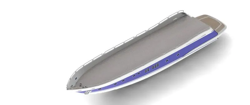
- To look realistic, the Sunseeker Predator Yacht rendered through PhotoView 360, which snaps attached in the above report.
- Thank you so much, MR. SRIKANTH sir to assist and help me to complete the project.