Photo Realistic Rendering
AMERICAN CHOPPER BIKE USING SOLID WORKS
Objective
- The objective of modeling the American chopper bike is to learn the different tools and features used in Solidworks through a realistic design.
- Another objective is, to assemble the parts and create a prototype or mule of a particular product.
- To create a realistic view of the model using photo view 360 by giving accurate color and material
Introduction
In this model, we would create/design different parts of a chopper bike in Solid Works using the various tools and features present in the software. Each part of the project will be designed separately and assembled. After the completion of the final design, the product will be covered by the material and color to look like a realistic view.
Design Methodology/approach
Parts requirement for the design
- Chassis
- Engine
- Fuel tank
- Gas tank
- Front-wheel
- Rear-wheel
- Front fork
- Pedal LH & RH
- Transmission Belt
- Kick Stand
- Front Fender
- Rear Fender
- Chain
Description of parts
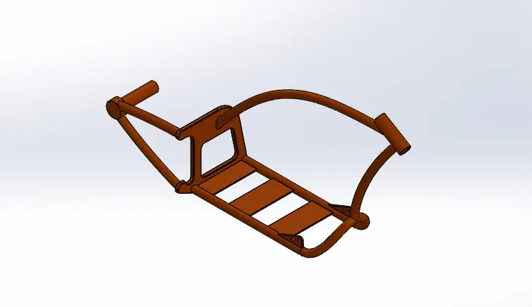
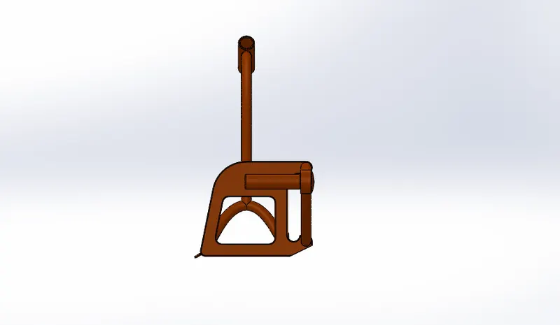
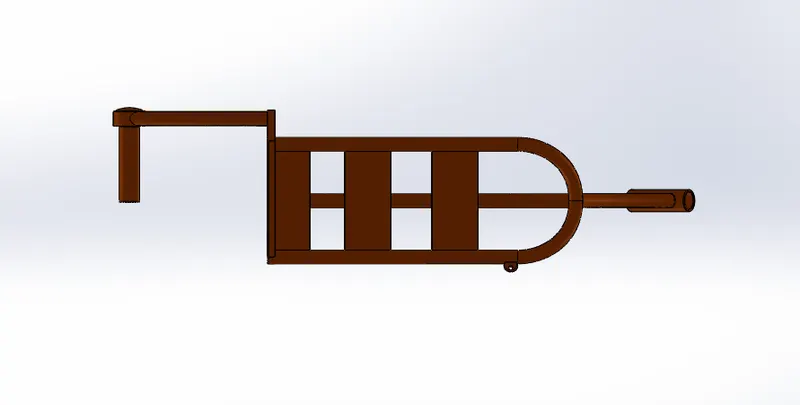
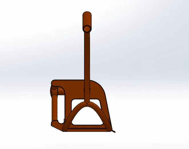
1.Chassis
Chassis is a part that is used to hold all components of an automobile vehicle like engine, fuel tank, wheel, etc.
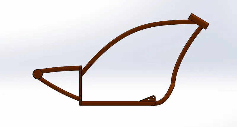
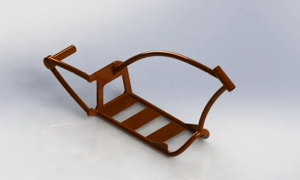
Tools & Features used
Boss extrude, sweep, mirror, chamfer, fillet, dome, split, combine, revolve, cut extrude.
2.Engine
The engine is a component, which is the heart of a vehicle. The engine converts thermal energy into mechanical energy.
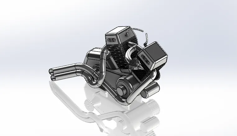
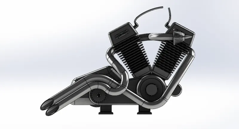
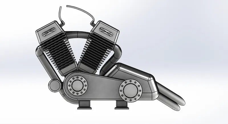
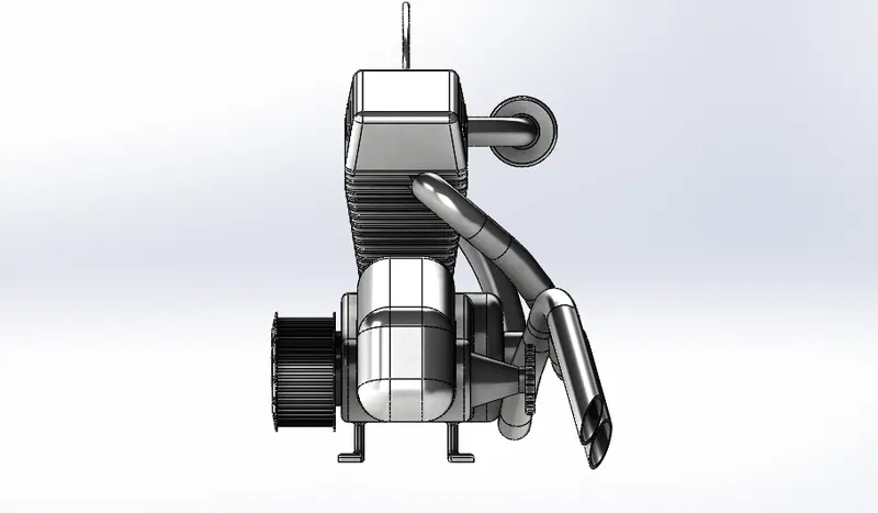
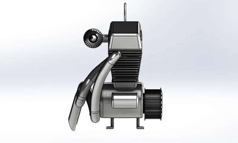
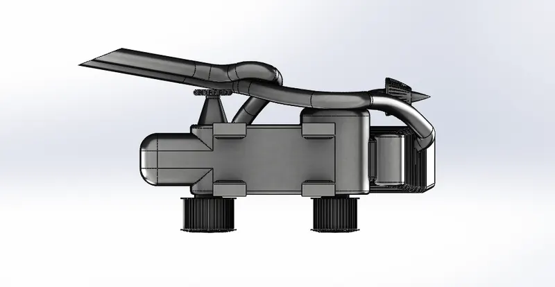
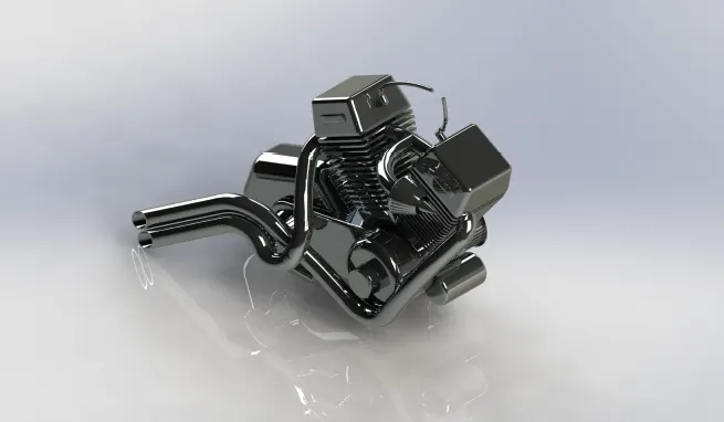
Tools & features used
Boss Extrude, Fillet, Revolve, Circular pattern, Dome, Cut Extrude, Mirror, Combine, Chamfer, Sweep, Plane, Linear Pattern.
3.Fuel Tank
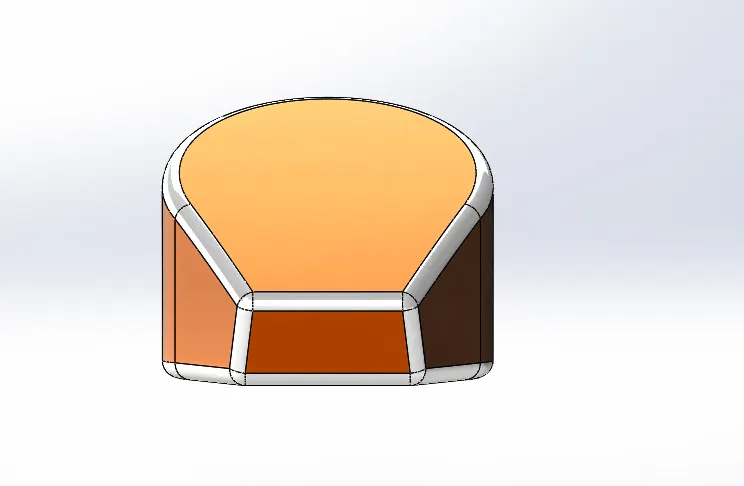
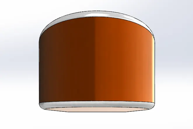
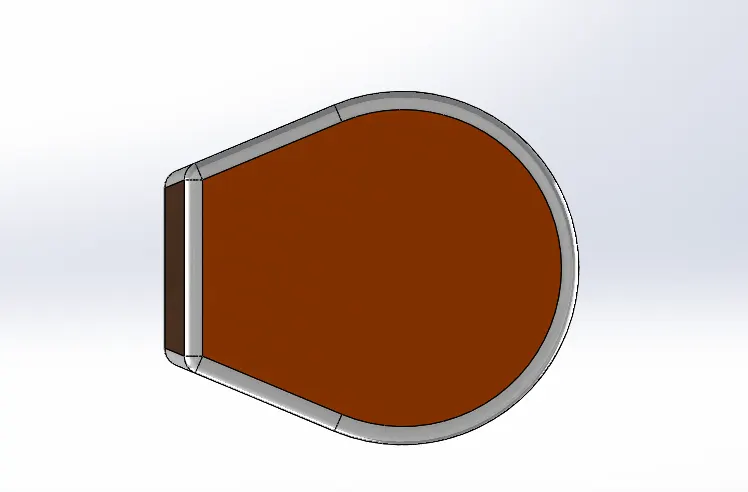
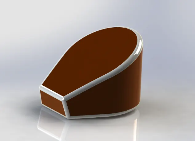
A fuel tank is also a necessary part of a vehicle used to store the required fuel in ample quantity.
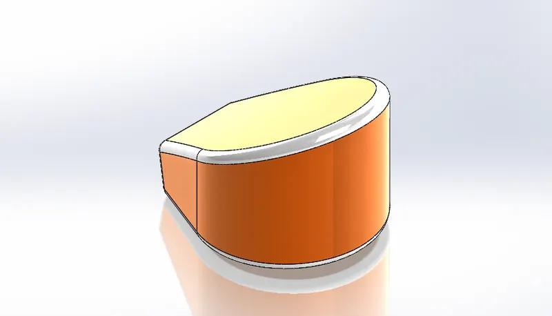
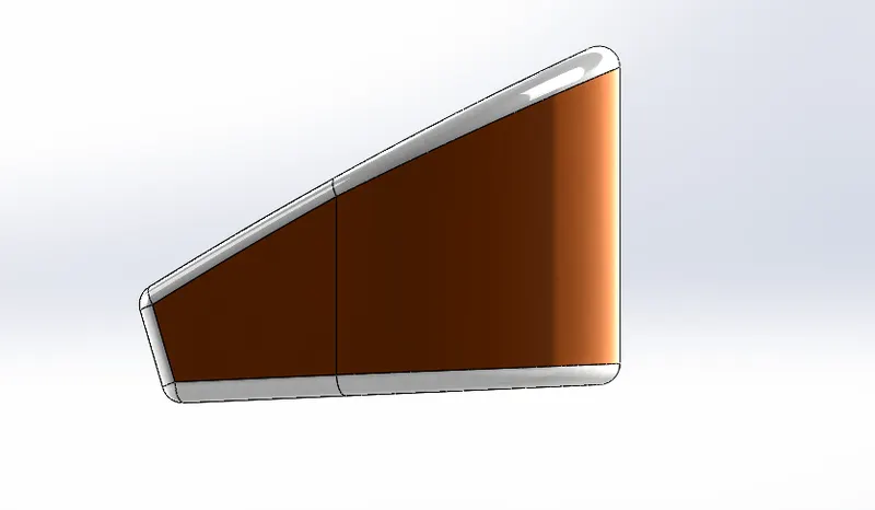
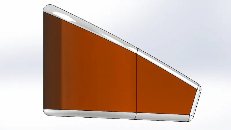
Tools & Features used
Boss Extrude, Combine, Fillet, Shell
4. Gas Tank
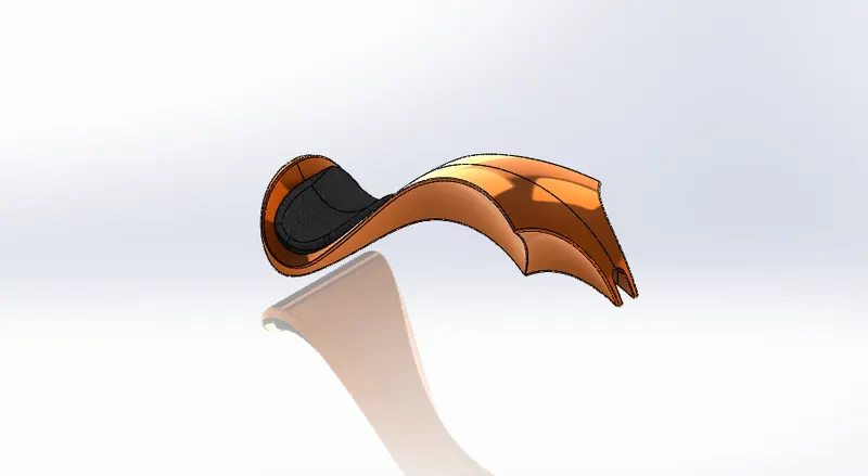
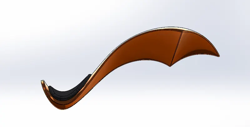
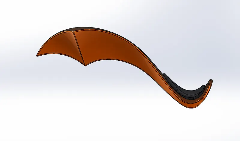
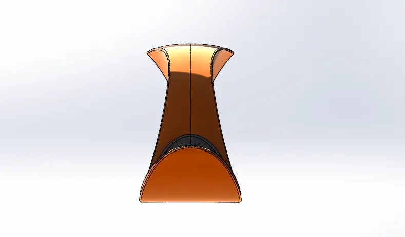
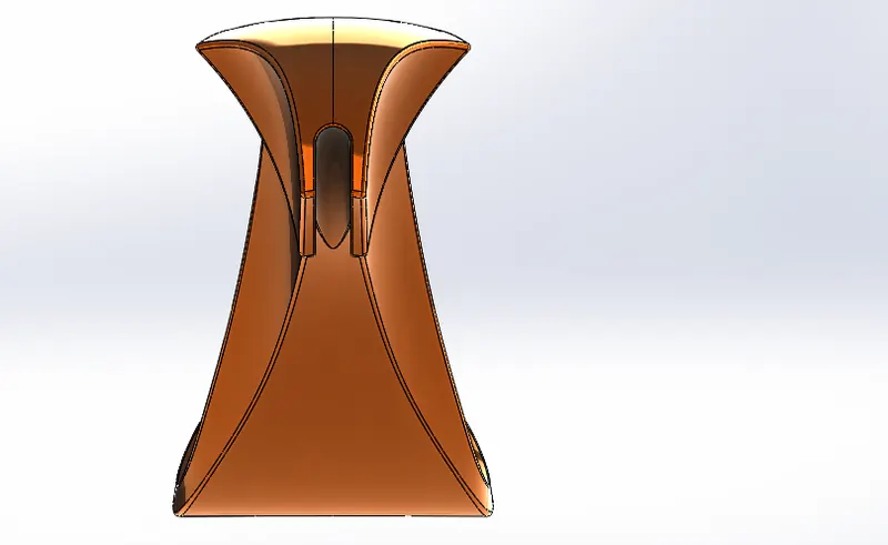
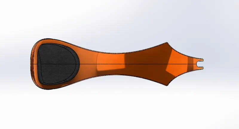
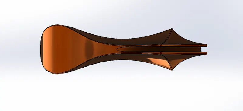
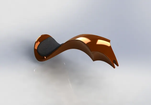
Tools and features used
Surface sweep, Surface Trim, Surface loft, Boundry surface, Mirror surface, Surface knit, Split line, Surface extrude, Fillet, Cut sweep, Shell.
5.Front Wheel
The wheel is a part of a vehicle that helps the vehicle to move forward by giving rotary motion.
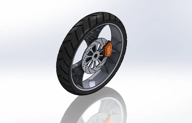
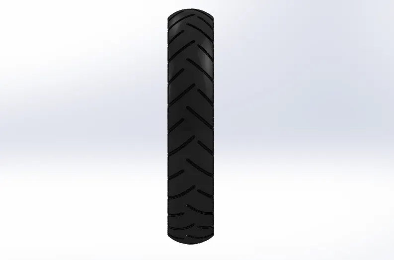
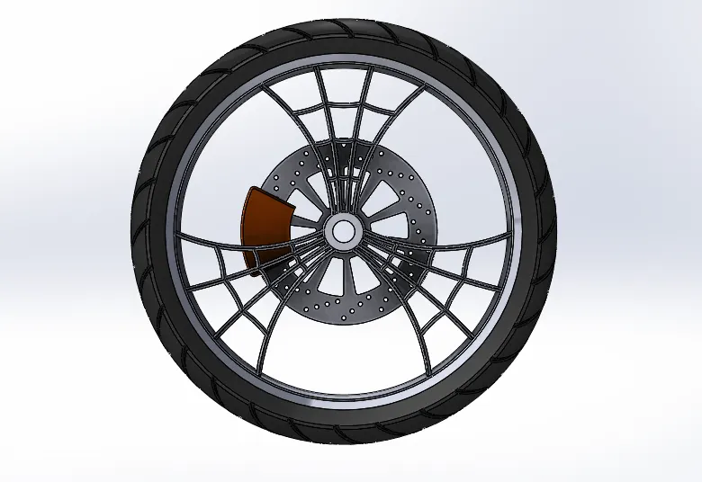
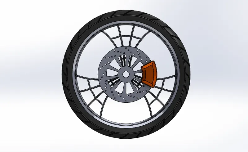
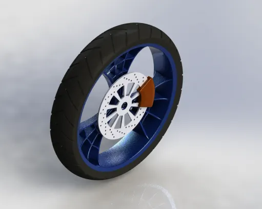
Tools & features used
Revolve, Boss Extrude, Cut Extrude, Cut Revolve, Circular Pattern, Combine, Chamfer, Fillet.
6. Rear Wheel
Same as the front wheel.
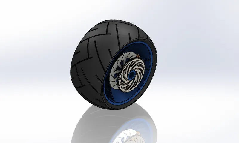
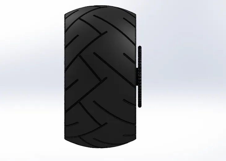
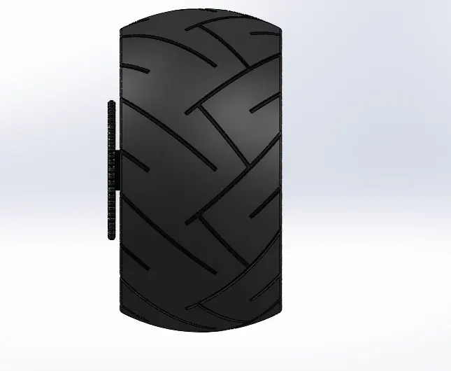
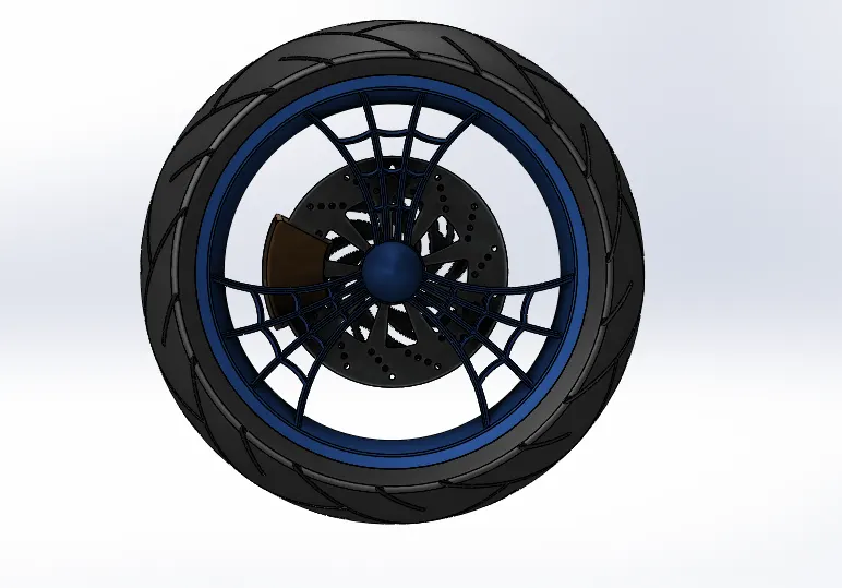
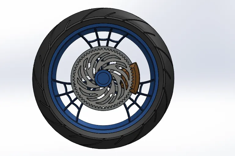
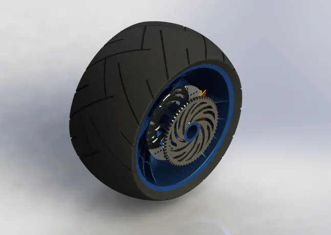
Tools & features used
Revolve, Boss Extrude, Cut Extrude, Cut Revolve, Circular Pattern, Combine, Chamfer, Fillet.
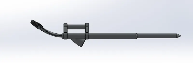
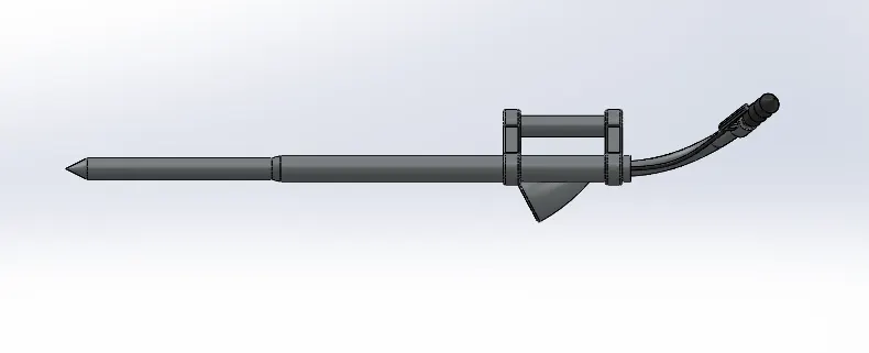
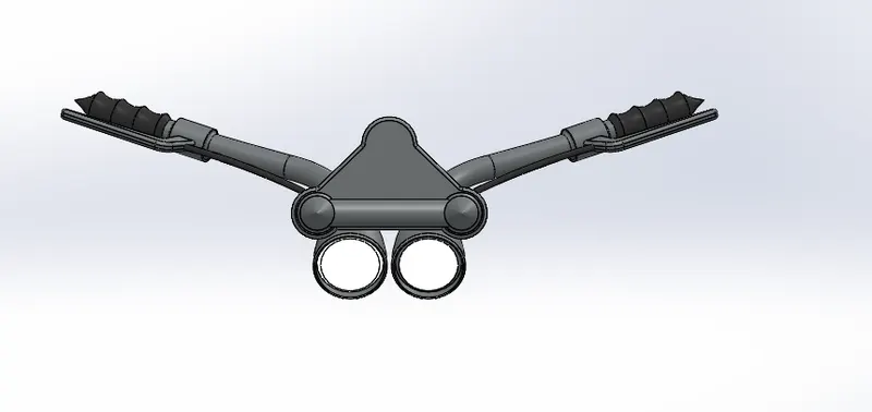
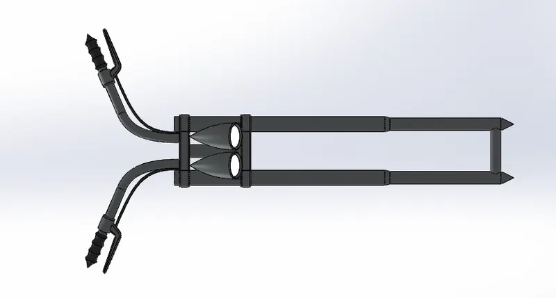
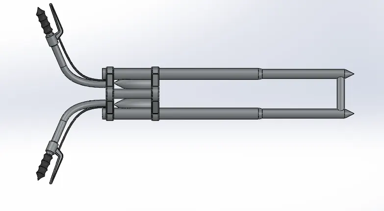
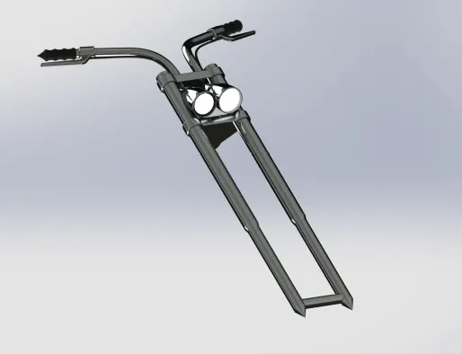
7. Front Fork
This helps in changing the direction of the vehicle. In addition, it holds the individual parts together with the headlamp, fender, and wheel.
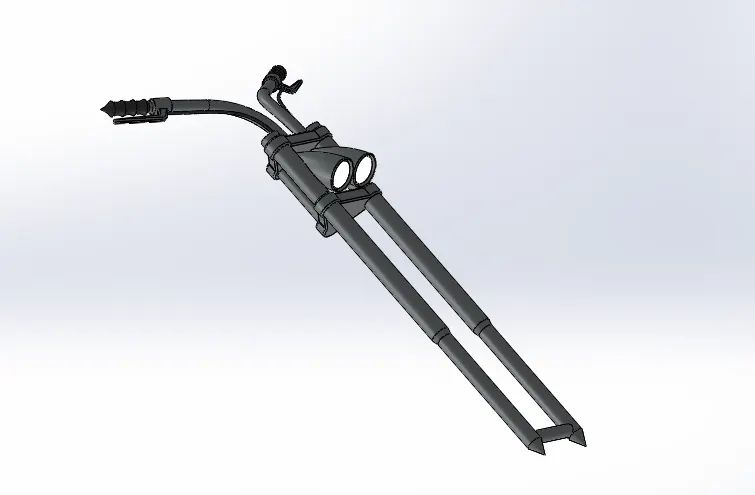
Tools & features used
Revolve, Boss Extrude, Fillet, Linear Pattern, Dome, Cut Revolve, Sweep, Mirror, Combine.
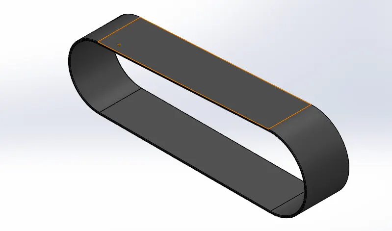
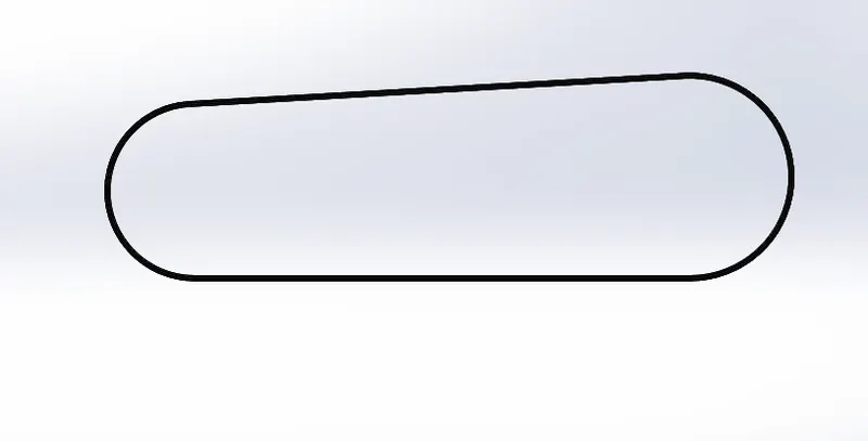
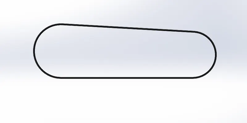
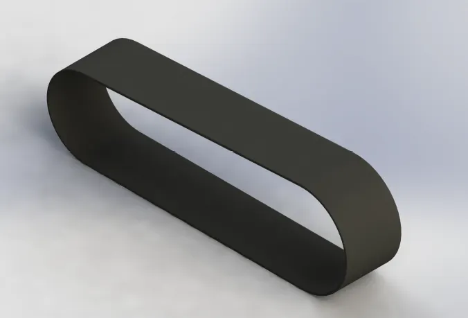
8. Transmission Belt
It's a part of a vehicle that is used to transmit the power from the engine to the output shaft.
Tools & features used
Boss extrude, Fillet
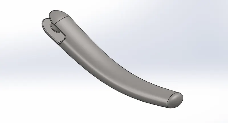
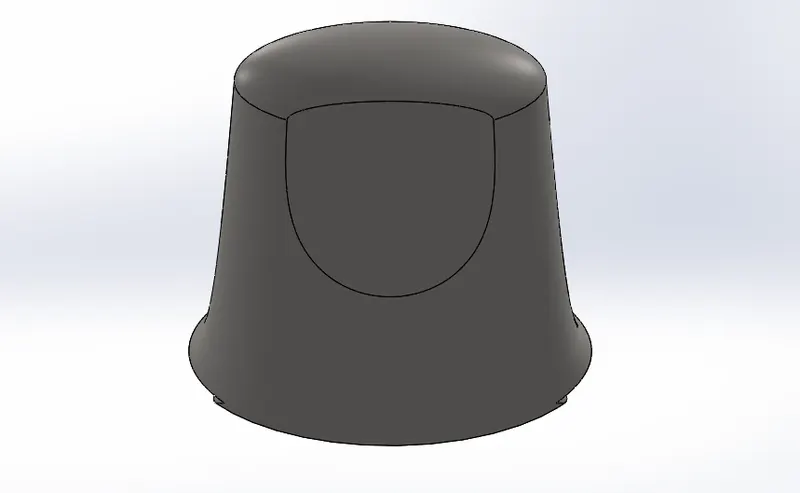
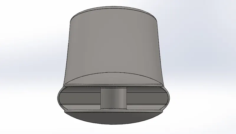
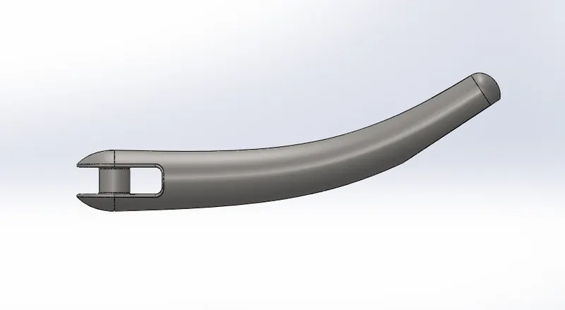
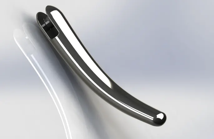
9.Kick Stand
It is used for parking purposes and to keep the bike in a steady position.
Tools & Features used
Loft, Dome, Cut Extrude, Split, Fillet
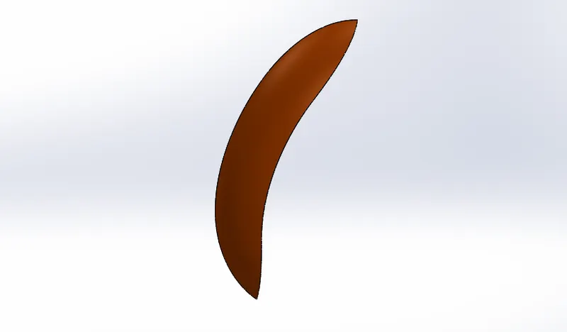
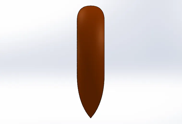
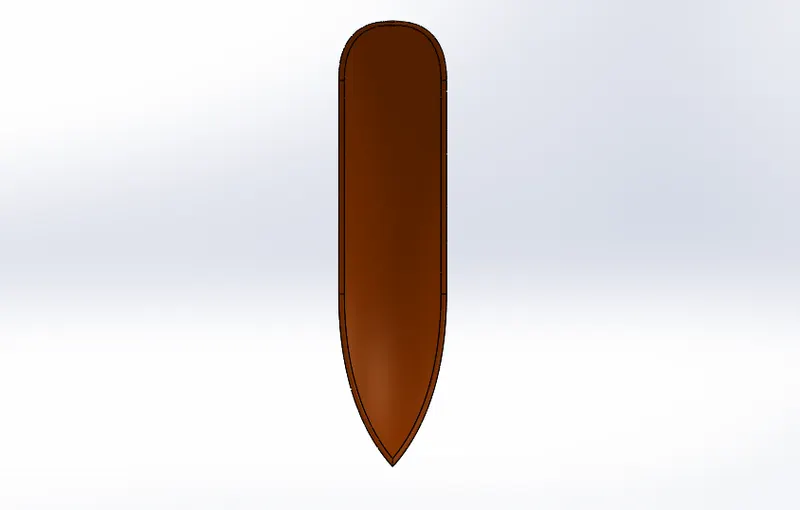
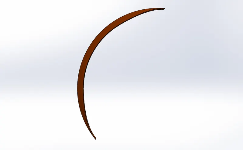
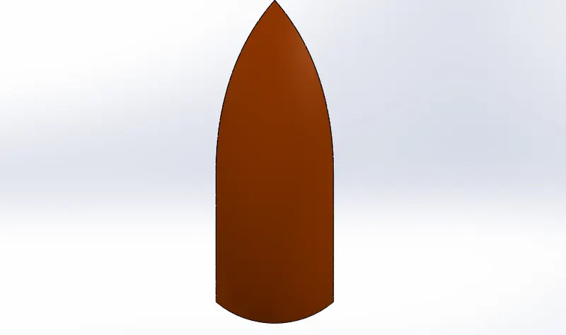
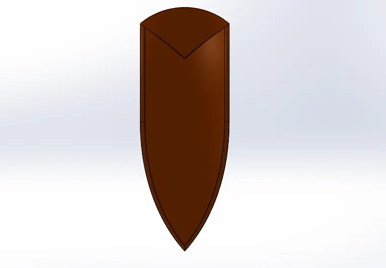
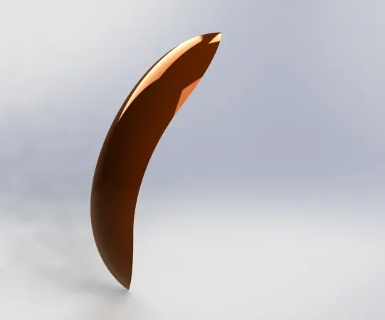
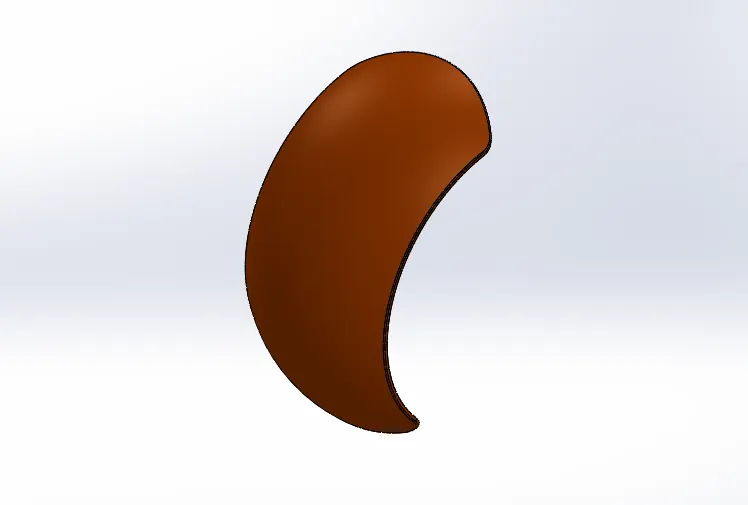
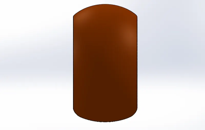
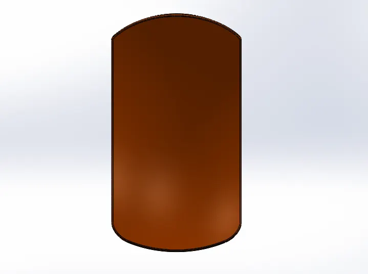
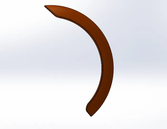
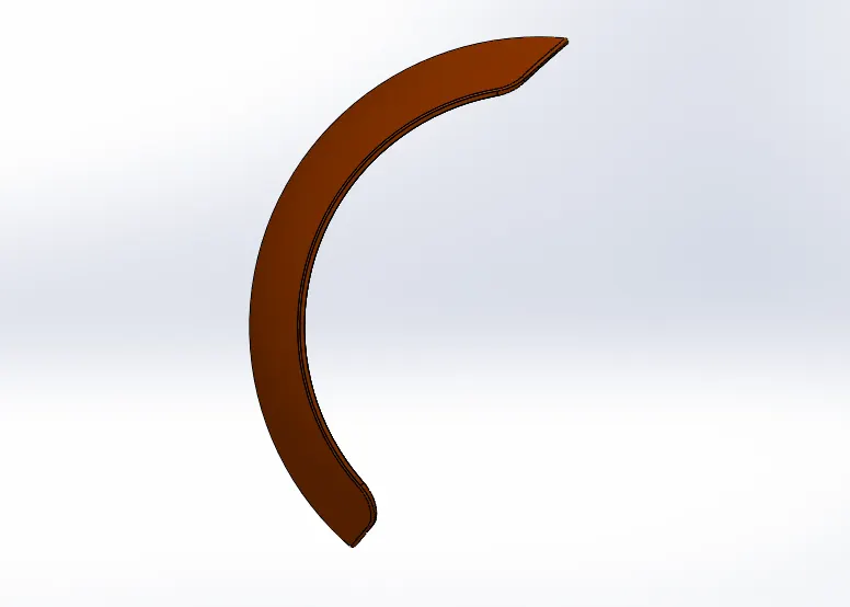
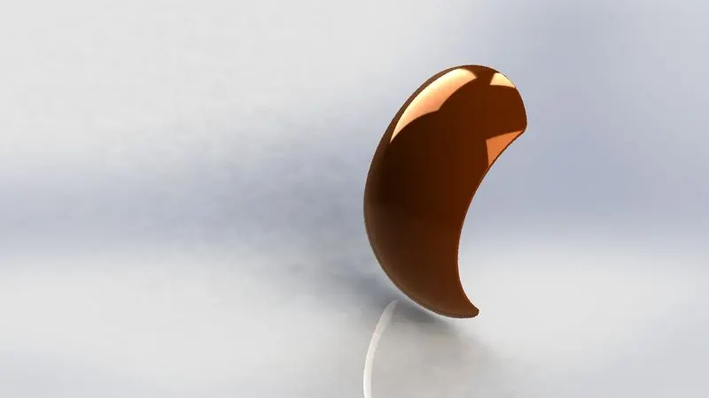
10,Front & Rear Fender
Fenders are used to prevent sand, mud, rocks from spraying to air from the rotating tire.
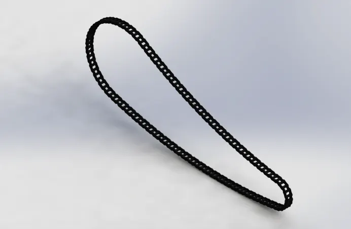
11.Chain
Chain is used to transfer power from output shaft to rear wheel.
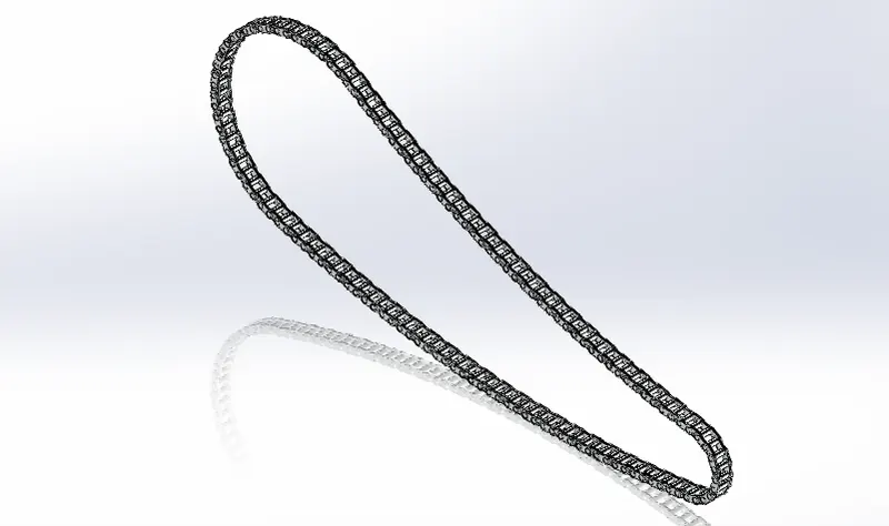
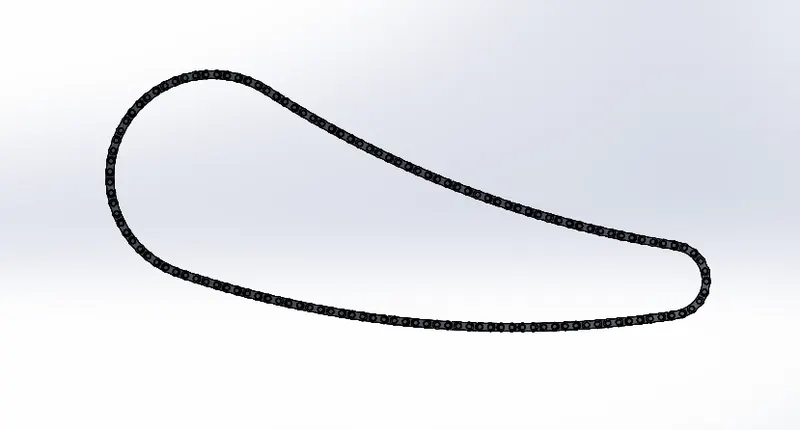
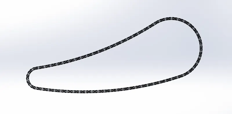
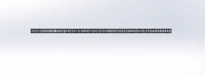
Tools & features used
Boos extrude, Fillet, Curved Pattern,
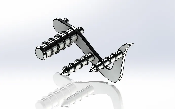
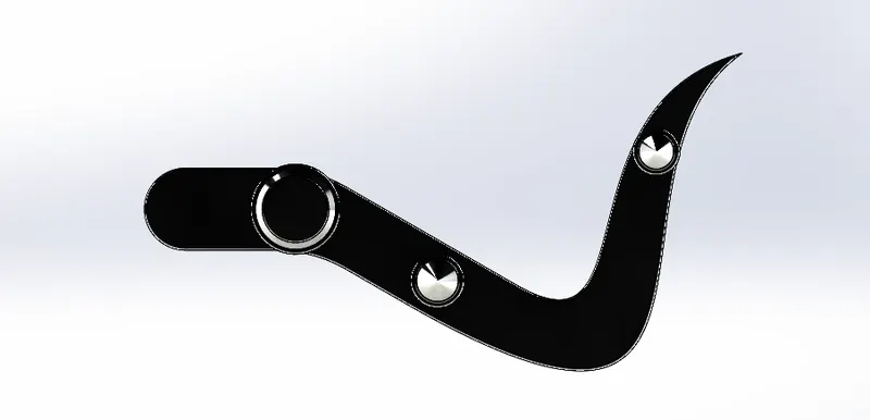
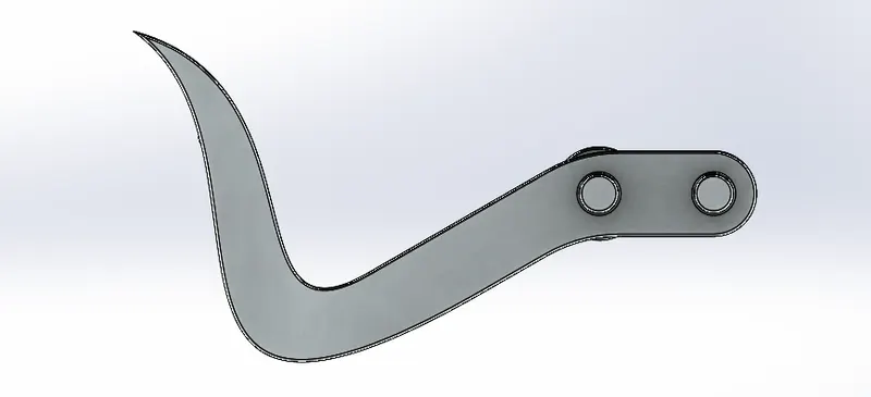
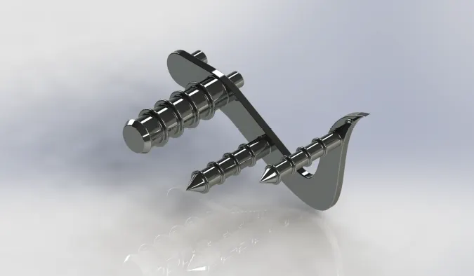
12.Pedal
The pedal is used to keep the foot of the rider and also to access the gears and brakes.
Assembling Of Chopper Bike
After the designing of individual parts, all the parts are assembled in the Solid work software.
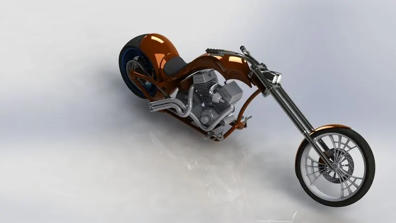
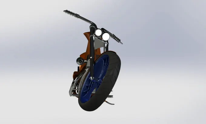
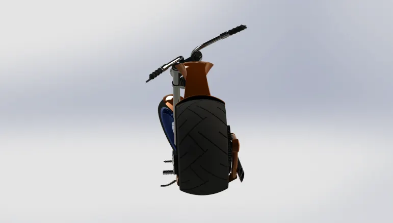
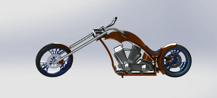
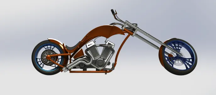
To assembly the model some mates and constraints have been used.
Conclusion
- In this model, the different parts of the American Chopper Bike have been designed separately in the Part modeling.
- After that, the parts are inserted in the assembling model area and assembled one by one by giving different constraints and mates.
- To look realistic, the assembled Chopper Bike rendered through PhotoView 360, which snaps attached in the above report.
- Thank you so much, MR. SOUNDER RANJAN sir to assist and help me to complete the project.