Advanced Sheet Metal Design Using NX Cad Challenge_1_Casing Design
DESIGN OF A CASING USING NX CAD
INTRODUCTION
In the 21st century, travel is an important part of our life to transport goods & human beings from one place to another through road, water, and airways. But to travel, we need medium i.e automobile vehicles. The automobile sector is a vastly growing industry nowadays. So the most important part in the growth of these industries is the Production and in which research, development, and design play a vital role.
Most parts of a vehicle's body are made of sheet metals for example all the doors of the car, the body of the airplane, the body on frame chassis, and its design construction is a difficult part among all the designs because a vehicle body has to provide different curvatures and different sizes according to the demand. The design of sheet metal requires some special skill sets and specialized equipment. So here we will learn some skills and will design a casing to be used in the automobile industry through NX CAD.
DESIGN METHODOLOGY / APPROACH
Here we will discuss some of the tools that we are going to be used in the software.
Before proceeding towards the casing design we have to set some parameters for the sheet metal.
First, we will set the Material thickness, bend radius, relief depth, relief width for the model as shown in the image.
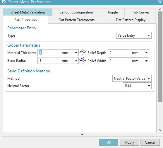
Tools used in the preparation of the model.
- Tab
- Flange
- Break Corner
- Dimple
- Normal Cutout
- Hole
- Mirror Feature
- Bend
- Unbend
- Rebend
Tools Description
Tab
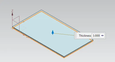
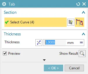
A tab is used to creates a base feature or we can say it add some material on the planer surface as per the sketch.
- Here we have drawn a rectangle with some length and width. And after clicking on the tool icon it created the feature with the given parameters shown in the image.
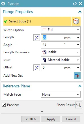
Flange
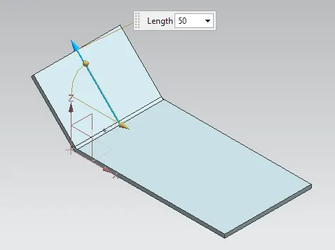
Add some flange with the base feature with some width and can create an angle between them.
When we click the upper edges of the drawing, the flange will go upward & when we click the lower edges of the drawing, the flanges will go downward.
Break Corner
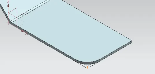
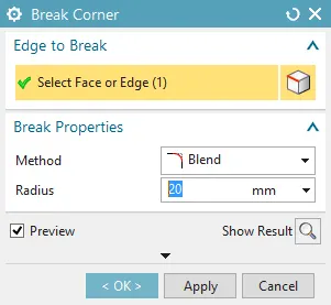
Break corner is used to add some fillet to the edged of the feature to avoid sharpness.
By selecting the faces it will automatically take all the edges of the adjacent faces.
Dimple
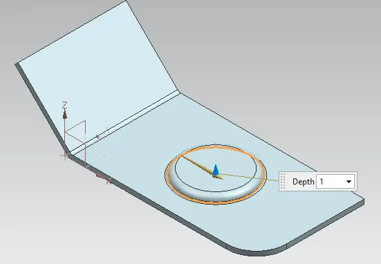
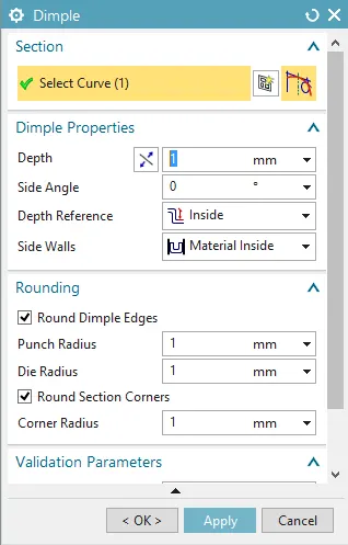
It lifts the area of the model inside the sketch that simulates a stamping tool.
We can create any type of sketch for the dimpling process.
Normal Cutout
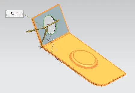
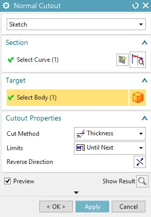
It removes material from the model as per the drawn sketch on the surface of the model.
Hole
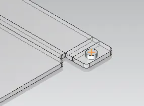
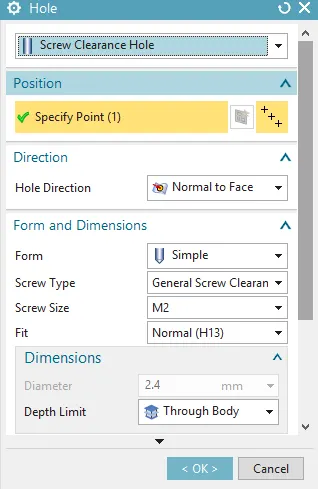
It adds holes in the features as per screw parameters. (Simple, Counterbore, Countersunk)
Bend
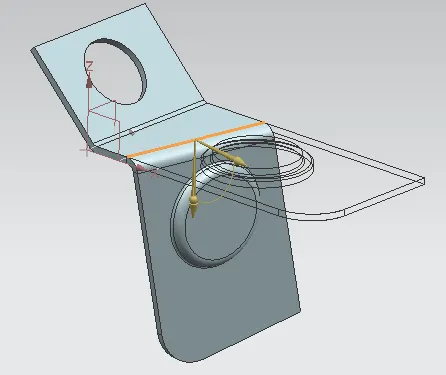
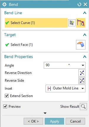
It Bends the model as per the sketch drawn in the face.
The black images show the before image of the model and the shaded model showed the current process of the model.
Unbend
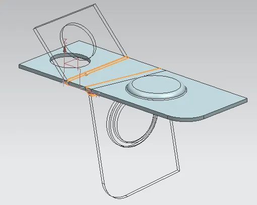
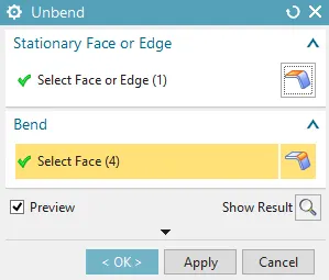
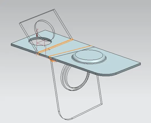
It bends the whole model into a flat surface for easy assessment of the sketch to be drawn.
Rebend
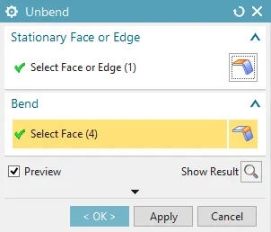
It bends the model again as before it had been.
Different view Of the model
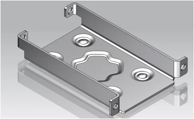
Isometric View
Front View
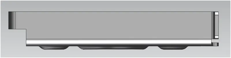
Top View
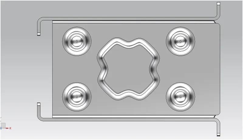
Bottom View
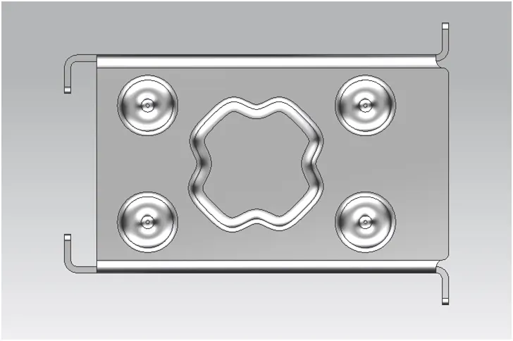
Right side view
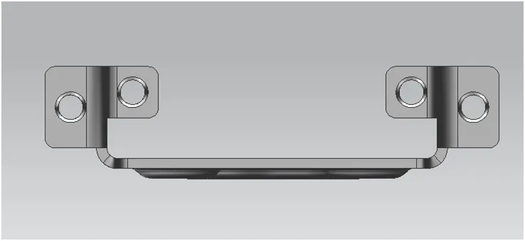
Drafting model of the design
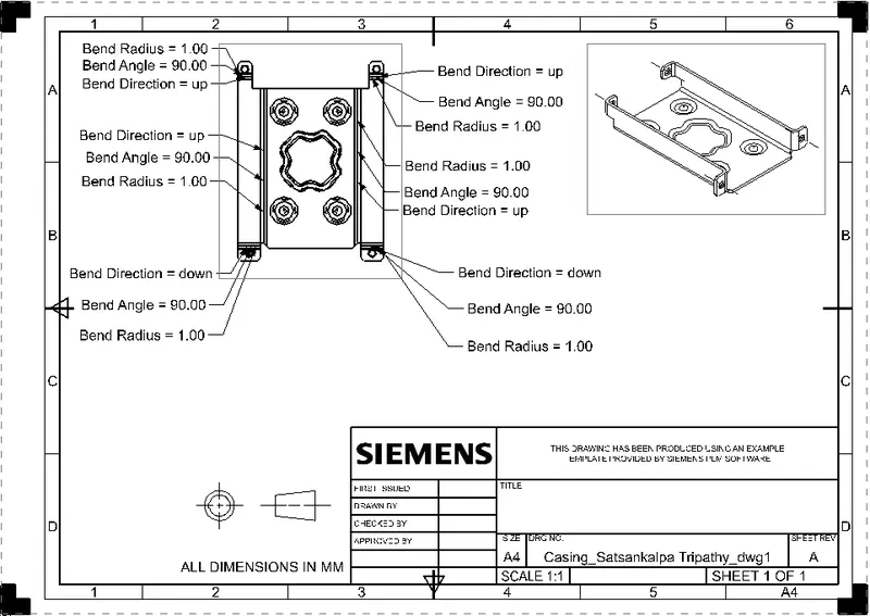
Conclusion
- Here we have drawn a sheet metal casing by using NX CAD.
- Also, we have created a drafting sheet of the model for future presentations.
- The model can be print on an A4 paper and can be represented in front of anyone.
- Thank you Mr. Nirmal Sir for your kind assistance to complete the mode.