Advanced Sheet Metal Design Using NX Cad Challenge_6_Bracket
Designing Of Bracket Using SIEMENS NX CAD
Introduction
We will create a metal bracket of sheet metal in Simens NX CAD.
The design will be formed into a 3D model from the 2D.
Objective
- The objective of this design is to create a bracket of sheet metal, which can be used in automobile, aerospace, and industrial work.
- The design contains various processes to create the model in accurate shape.
Tools Used
- Counter Flange
- Hole
- Unbend
- Rebend
- Normal Cutout
- Break Corner
- Bead
Design Methodology
1.Counter Flange
Counter flange used to add material to the sheet metal sketch as per the drawing by extruding.
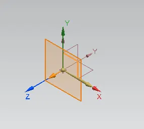
- We will select the XZ plane for the creation of the sketch for the counter flange.
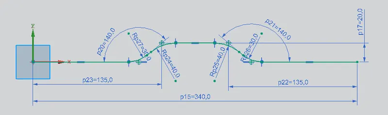
- The below sketch is created in the plane.
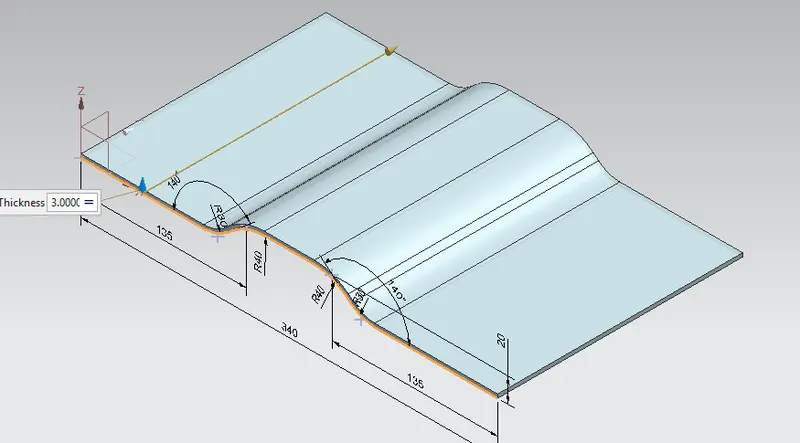
- After finishing the sketch, we will create a counter flange of an infinite length of 200mm with a thickness of 3mm.
Normal Cutout
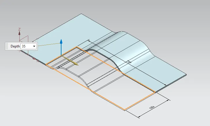
This tool is used to remove material/cut the material by projecting a manually drawn sketch into it.
- We will create a normal cutout in the top plane as per the given dimension.
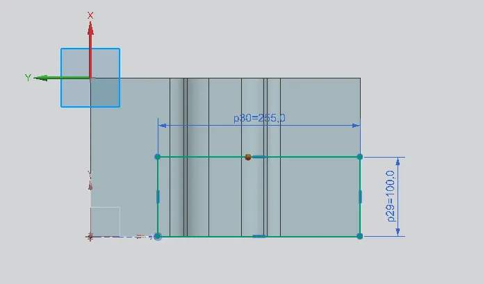
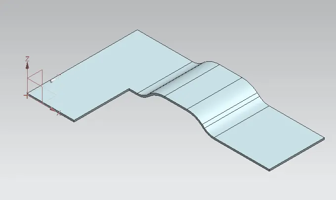
- After the process, the model will look like this.
Break Corner
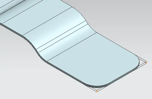
- The break corner is used to add a fillet to the edges of the corners to avoid sharpness.
Unbend
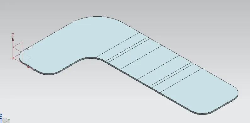
Unbend is used to make the whole drawing into a flat surface.
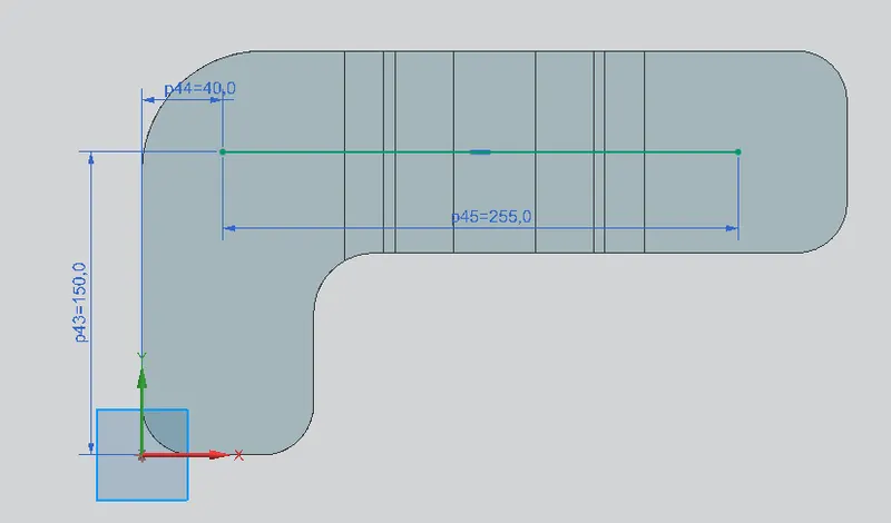
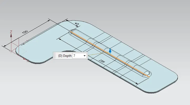
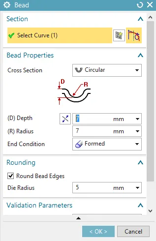
Bead
Bead is used to lifts the material along the counter of a sketch.
- The sketch is drawn above the top surface to form the bead.
Hole
It is used to add holes to the solid body with an option for counterbore, countersunk and threaded.
The point has created on the surface for hole positioning.
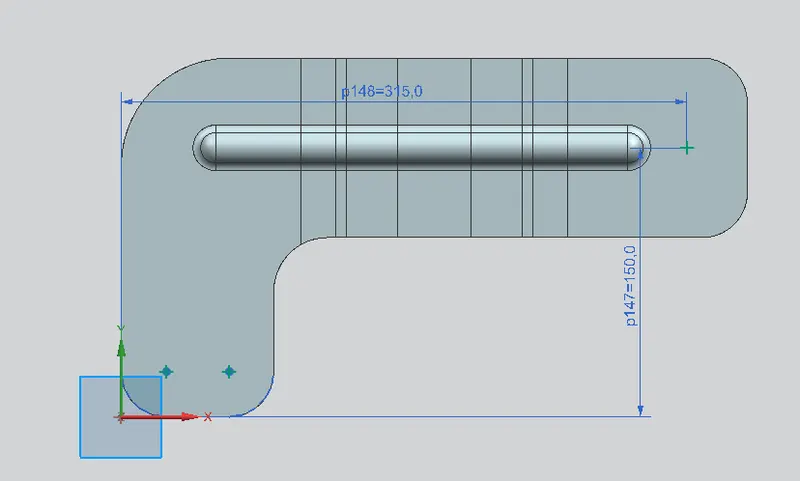
- After finishing the sketches the general hole with a diameter of 20mm has created in the model.
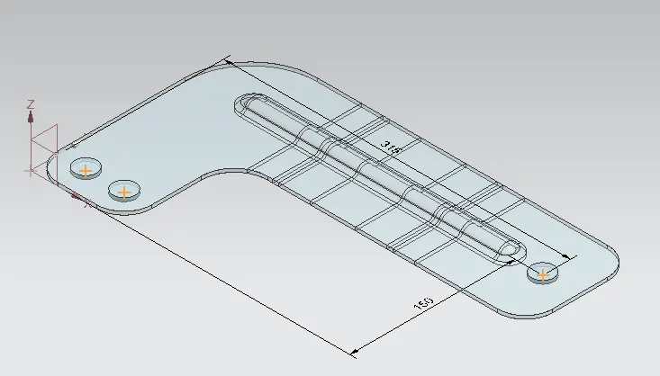
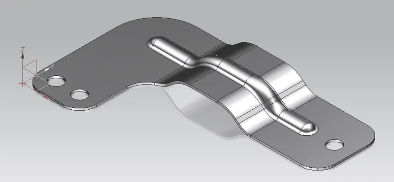
Different Views of the model
Isometric View
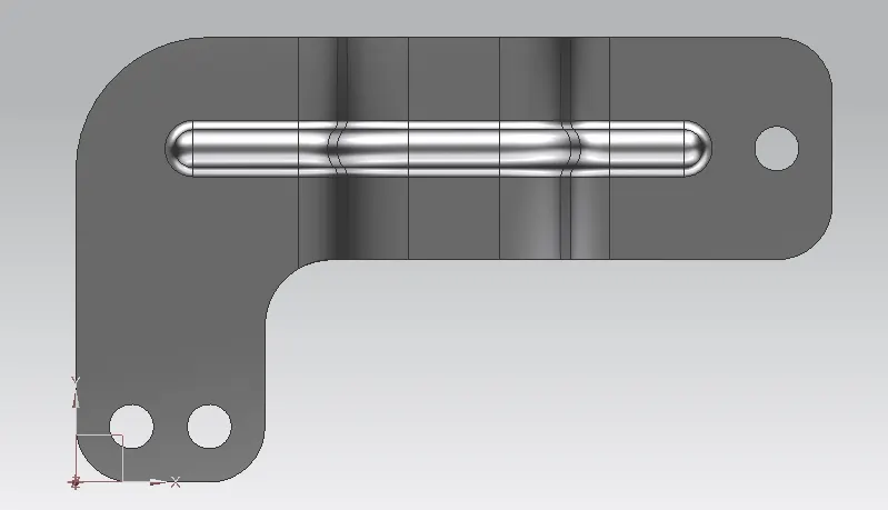
Top View
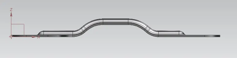
Front View
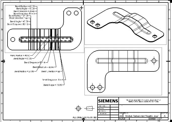
Drafting image of the model
Conclusion
- Finally the model has been created with the drafting image.
- Different views of the model have been created.
- The model is added with some material to look realistic.