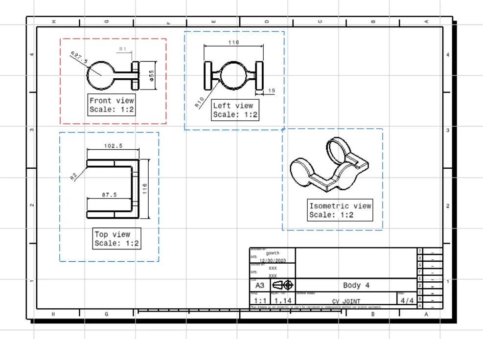
QUICK RETURN MECHANISM AND CV JOINT
AIM:
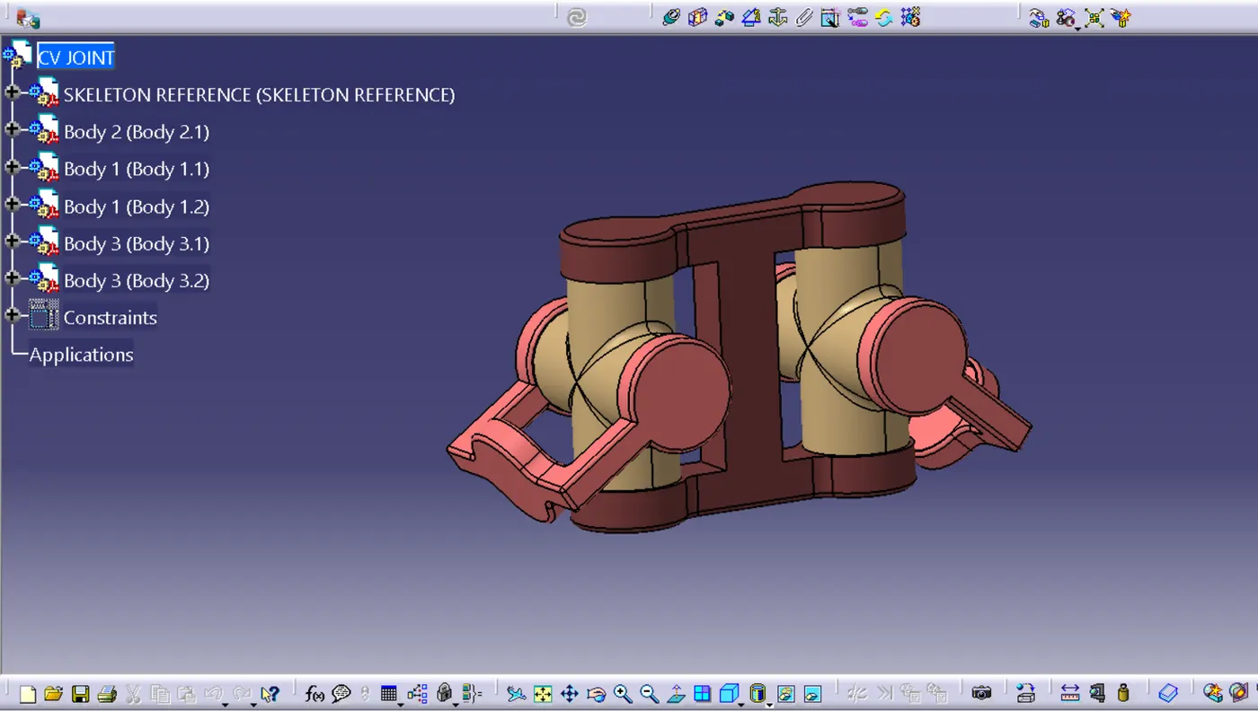
To create the individual parts, assemble the CV joint and quick return mechanism, and create a 2D drawing using the CATIA software.
PROCEDURE:
The procedure is as follows:
1. Firstly, the individual parts of the CV Joint and Quick Return Mechanism were drawn in the sketcher workbench and checked for constraints (iso constraints). The next part is carried out once the constraint is checked using the sketch-solving status tool.
2. Now, part features like the pad, fillet, mirror, pattern, and other options are used using boolean operations like ADD, REMOVE, and UNION TRIM.
3. Moreover, after creating all the individual parts, the assembly has been done, providing constraints to the parts like coincidence, contact, fix, and other constraints.
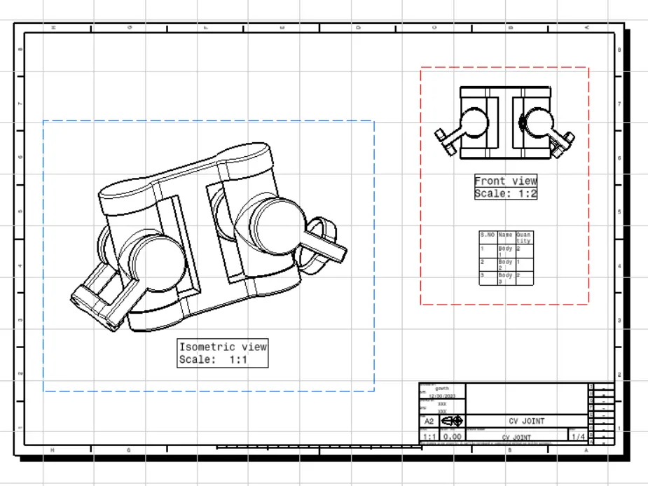
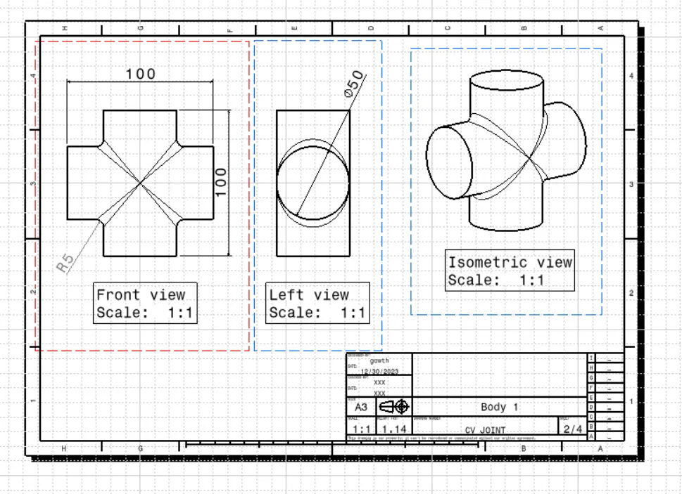
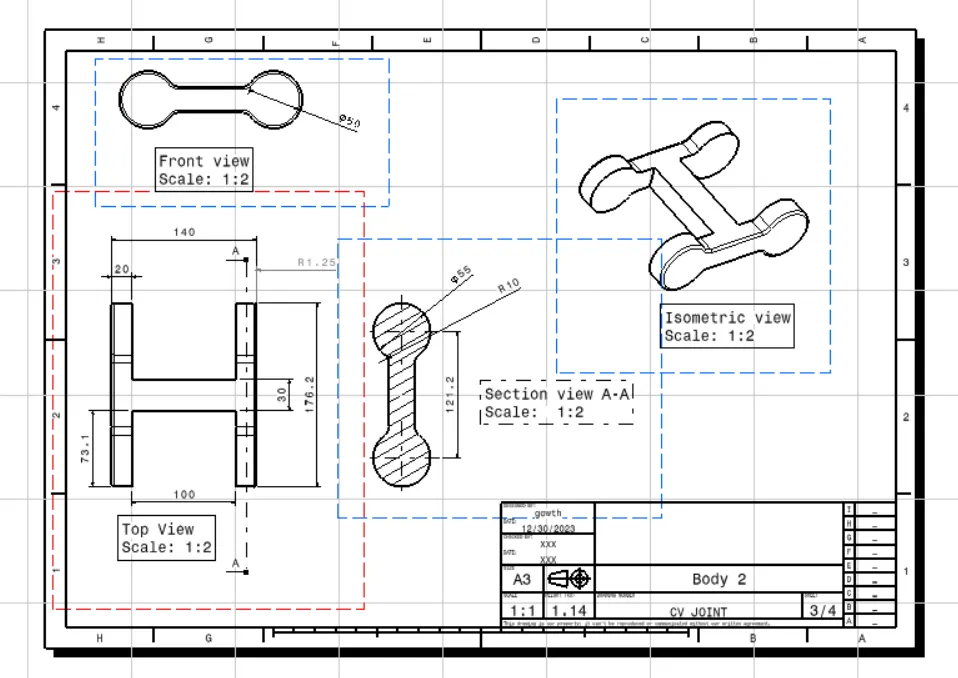
4. Finally, the 2D drawing has been created for both the CV joint and the quick return mechanism. Here, the different views (front view, top view, bottom view, side view, and isometric view) were used and shown on the drawing sheet, and the title and frame-block have also been inserted at the bottom of the page.
QUICK RETURN MECHANISM:
The images are as follows:
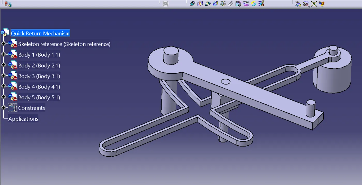
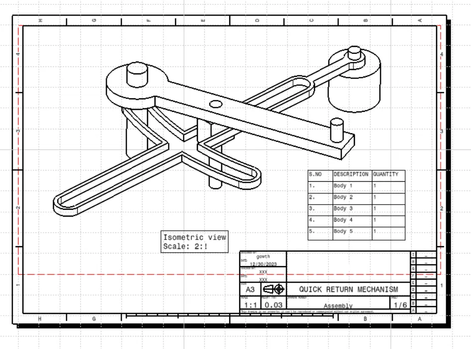
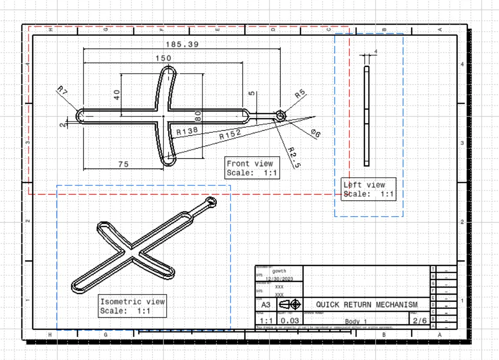
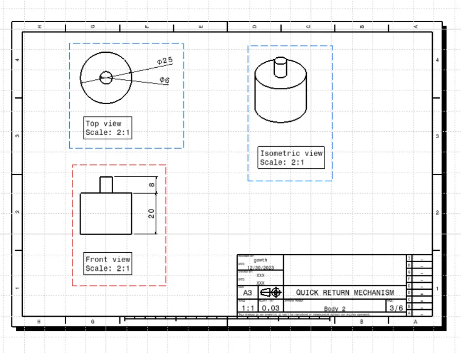
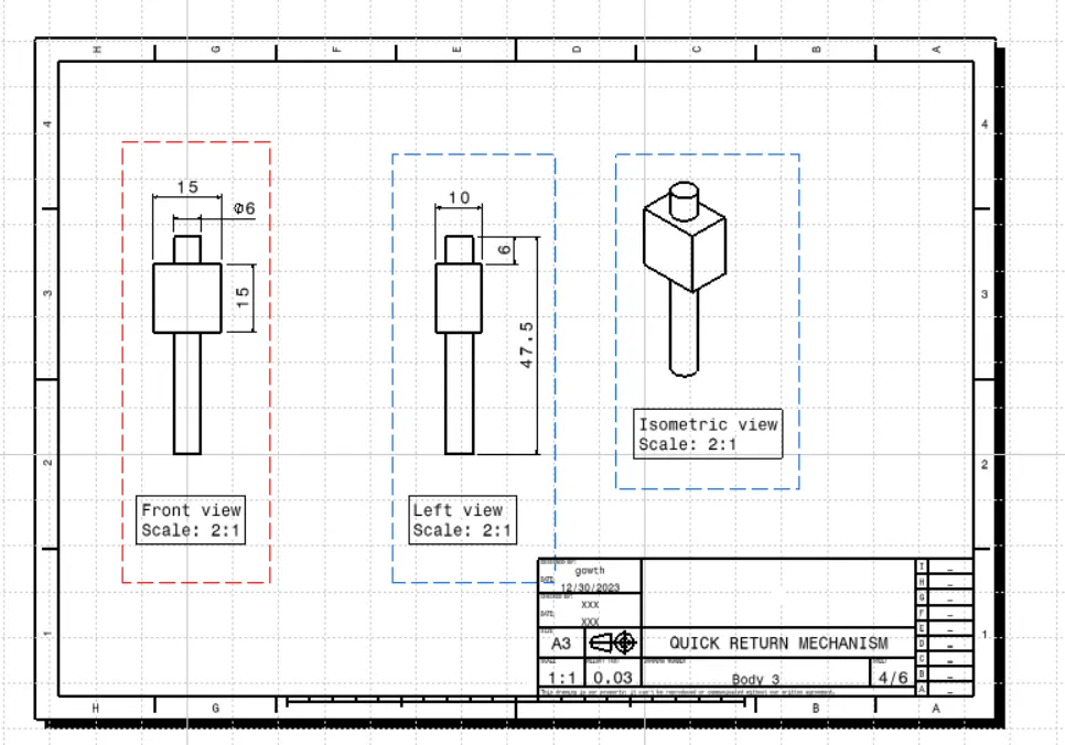
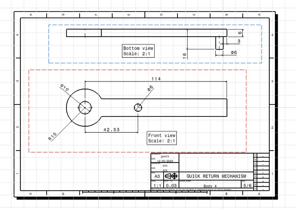
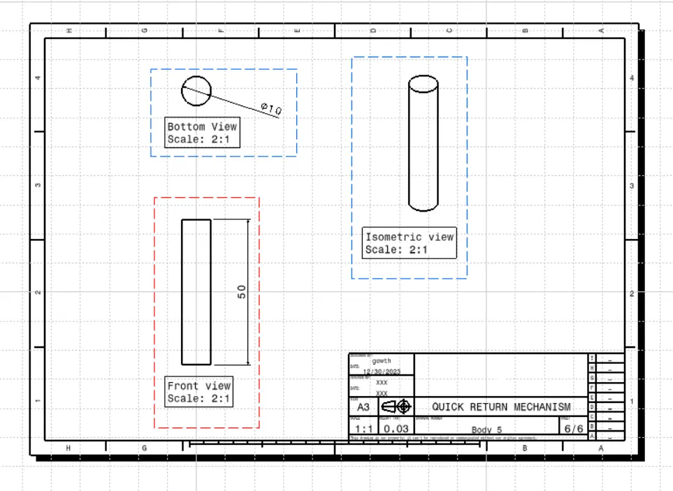
CV JOINT:
The images are as follows: