Projefct 1_Comparative study of different storey buildings for Seismic forces
Aim - To model and analyse the different kinds of buildings and conduct a comparitive analysis between the models based on different factors.
Introduction - Buildings oscillate during earthquakes whoch causes inertia forces to be developed in the building.
The intensity and duration of oscillation and the amount of inertia force depends on the features of the building which is called dynamic characteristics of the building.
Every building has a number of natural frequencies at which it offers minimum resistance to shaking induced by external effects and internal effects. These natural frequencies and asssociated deformation shape of a building constitue a natural mode of oscialltion.
The mode of oscillation with the smallest frequency is called fundamental mode.
These are the buildings which have to be modeled and analysed
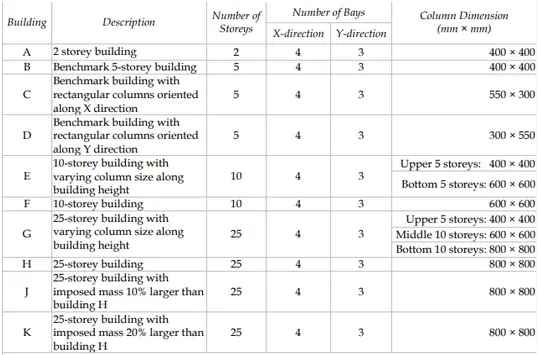
Step 1 - Modelling building A
1 open ETABS and change the settings for model initialization as follows
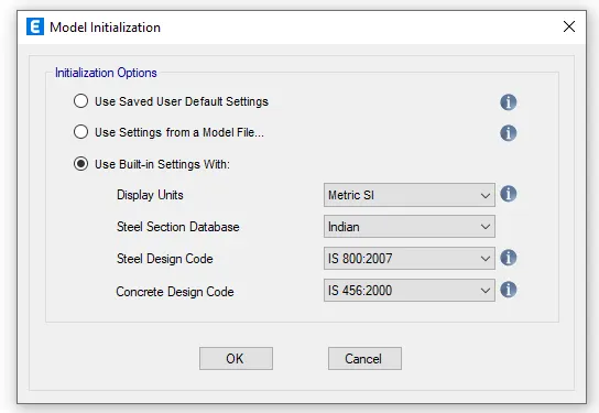
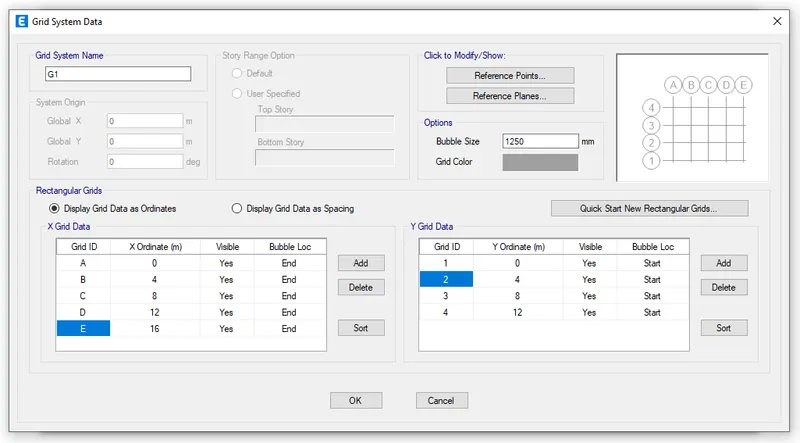
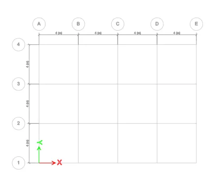
Press OK and then select CUSTOM GRID SPACING option.
Custom grid spacing will be provided as follows
Press ok and select CUSTOM STORY DATA option to edit storys and input the following details
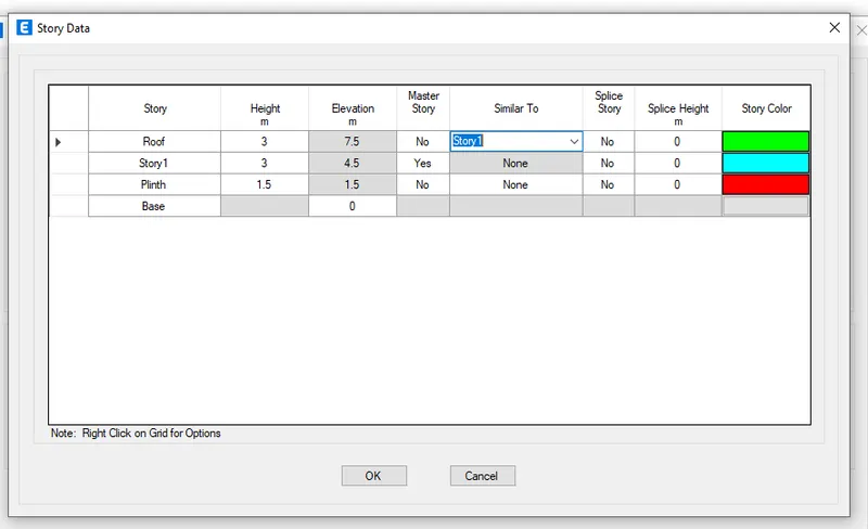
Grids have been created
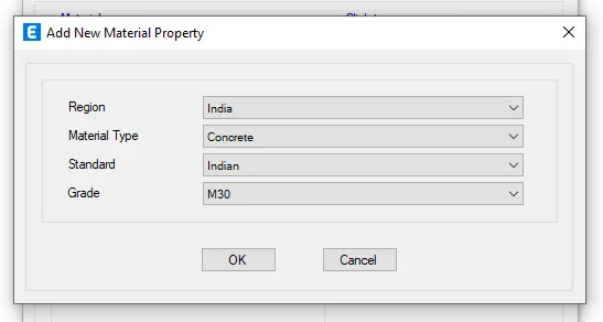
In story 1, material properties will be edited as follows. First will be M30 grade concrete.
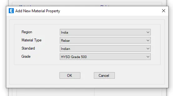
We need to add rebar for longitudnal reinforcement as follows
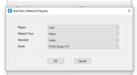
we need to add rebars again for shear reinforcement
Materials have been added. we need to add sizes of beams, columns, slabs whoch will be done from the define tab.
Column size 400x400 has been added
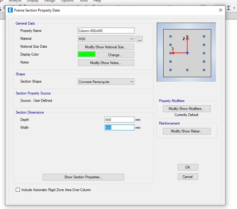
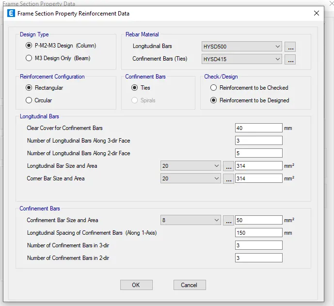
column reinforcement data will be as follows
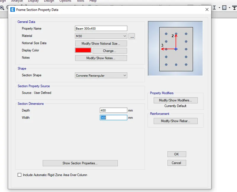
Beam data needs to be added as follows
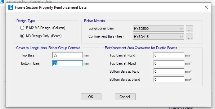
reinforcement data will be added as follows.
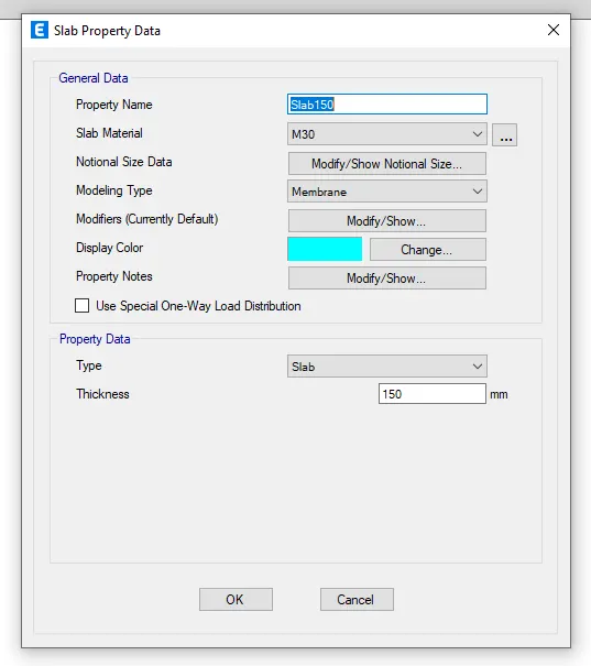
slab will be added from defin tab by selecting slab sections and giving it the following properties
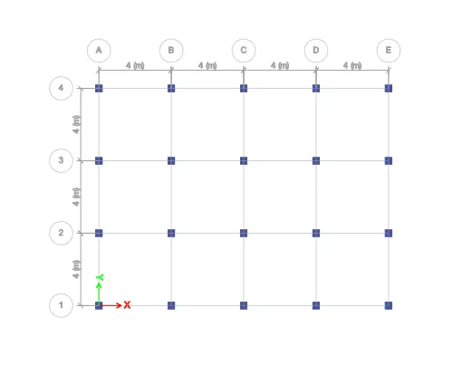
columns have been added using quick draw columns command
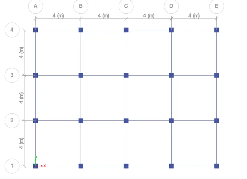
beams are added using quick draw beam command
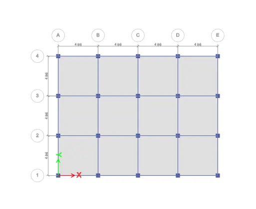
going to story 1 from plan option and keeping similar stories option on slabs have been created on story 1 and rood
go to base plan option, slect one story option
select all the joints
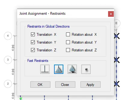
from assign tab the restraints will be added as PINNED
the load patterns will be added from the define tab in the following way
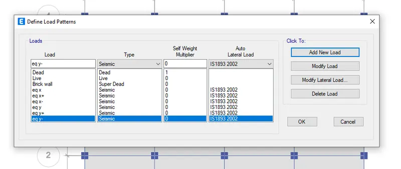
we will also be modifying the lateral loads of the seismic forces which will be done from the modify lateral load button
EQ x load is modified in the following way and chaging the criteria as follows
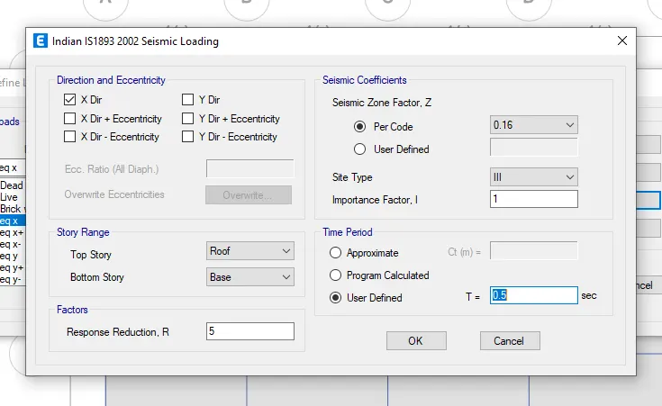
similar criteria will be addded for all the remaining earthquake loads
we need to assign the live loads which will be done from the assign tab
by keeping the plan on story 1 and keeping similar stories option on, live load is added from the assign tab as follows
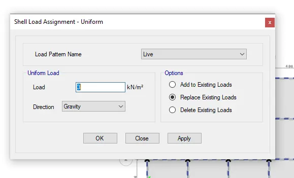
live load has been added
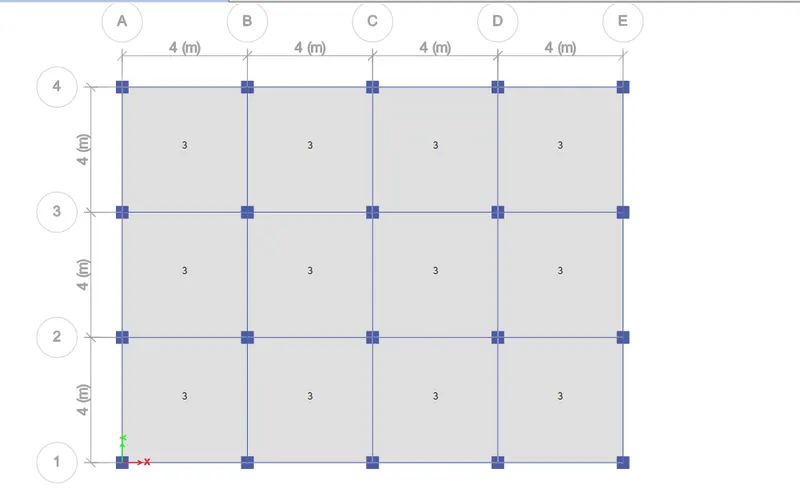
the dead load hsa to be applied on the beams which will be done by selecting them from the SELECTtab and then selecting OBJECT TYPE option
from assign tab, we will select FRAME LOADS and then DISTRUBUTED
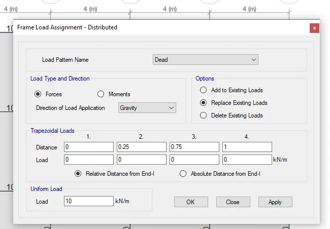
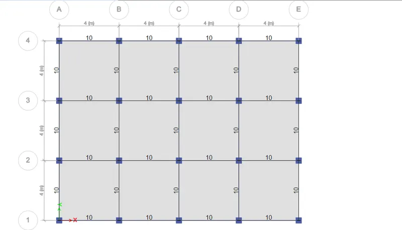
the load has been addded
the MASS SOURCE will be modified from the define tab as follows
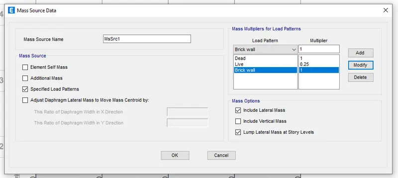
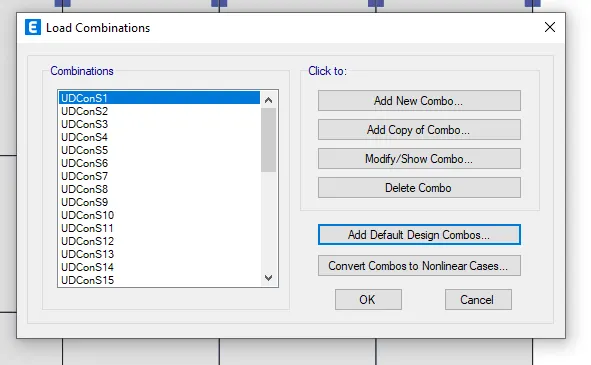
we need to add load combinations which will be added from the define tab as follows
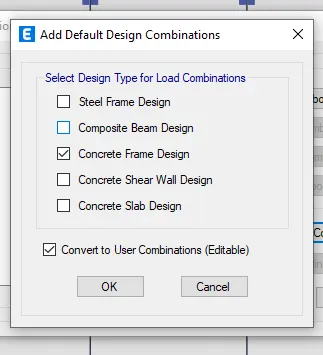
the combinations have been generated
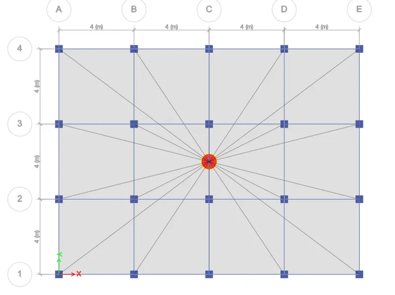
we will add diaphgrams by selecting the floor from select tab
the from assign tab we will select shell option which wil open diaphgram dialog box as follows
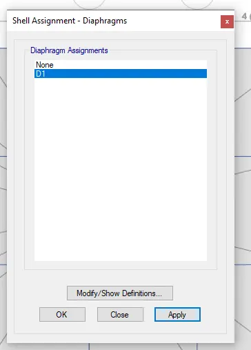
after selecting the D option, we will press apply
diaphgram has been added
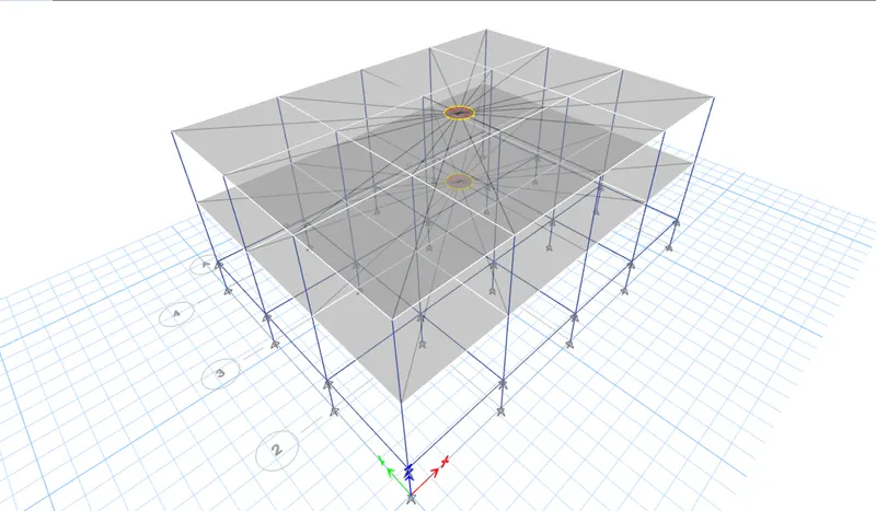
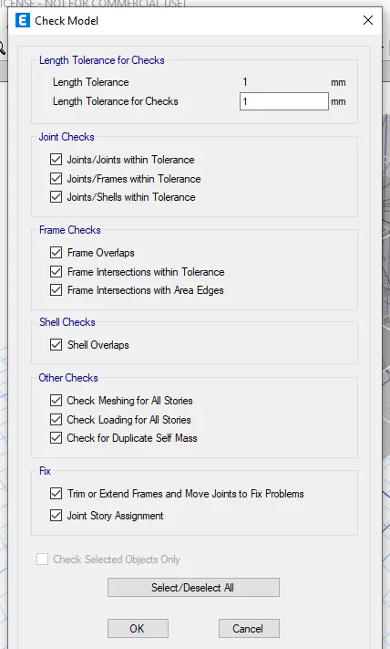
from the analyze tab we will select, check model option and select all the options as follows
model has been checked

we need to run analysis on the model by hitting F5 or selecting the run analysis option
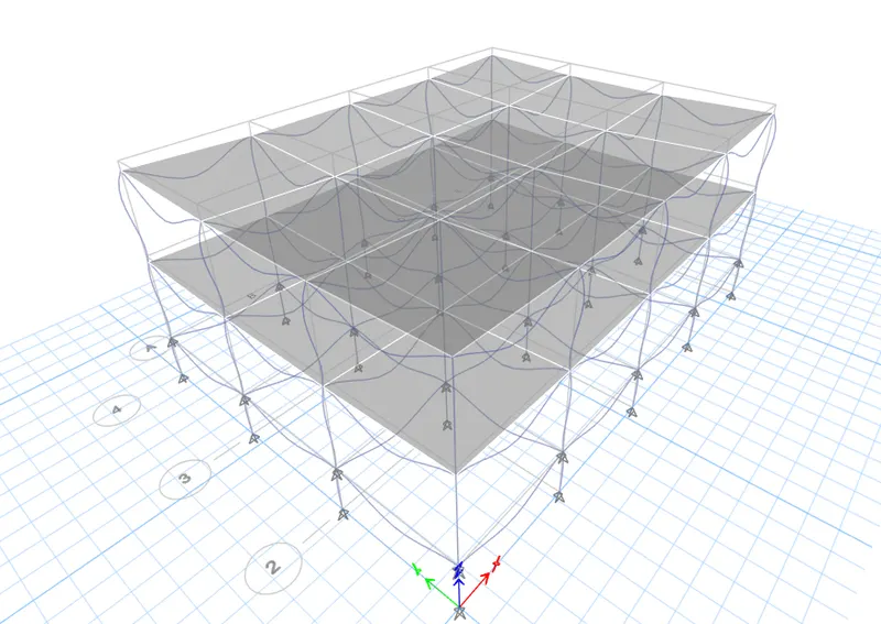
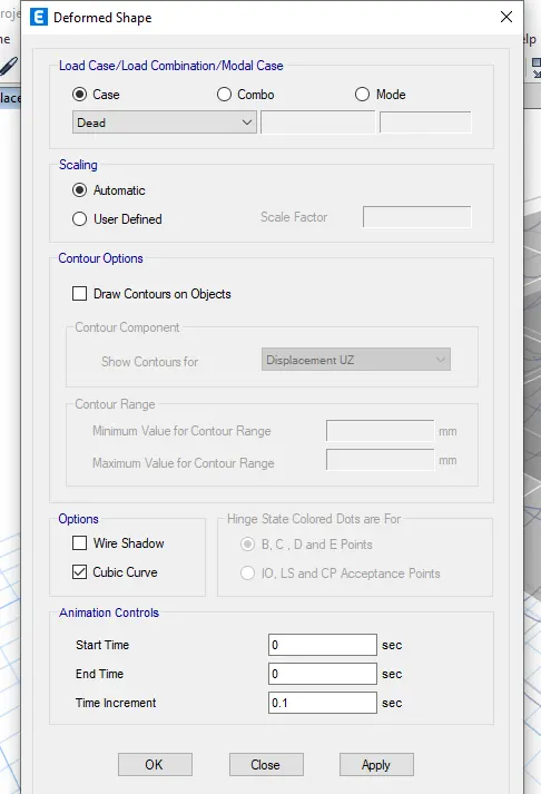
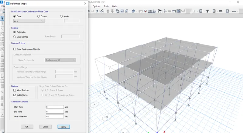
select show deformed shape option the following dialog box will open
for eq x
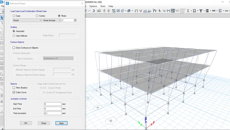
mode case option selection
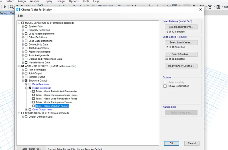
from the display tab, select show tables option select the following options
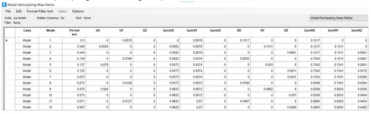
modal mass participating ratio for building A is ready
Modelling for building B
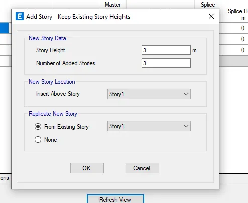
unlock the model and edit the story data option as follows
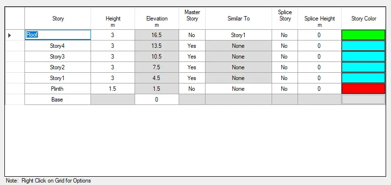
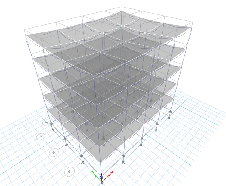
new model has been checked

model is ready for analysis
analysis has been done
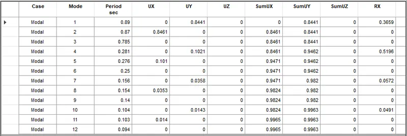
modal mass participating ratio for building B
Modelling for building C
unlock building B
from section properties we will change the column size
from the select tab we will select the columns and from assign tab we will change the columns to 300x550 size
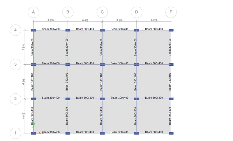
we will analyze the mode now. it gives the following results.
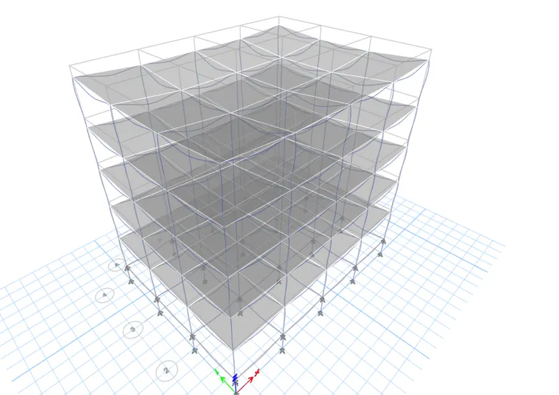
after running the analysis it gives the following results
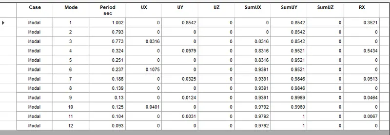
model mass participation for building C
Modelling for building D
unlock building C
select the columns from select tab
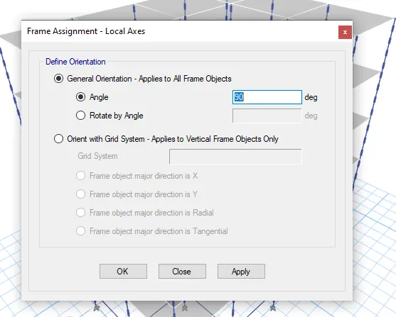
from assign tab, we will assign the local axes as follows
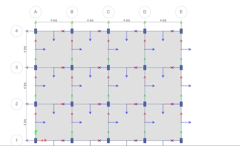
columns are oriented as follows
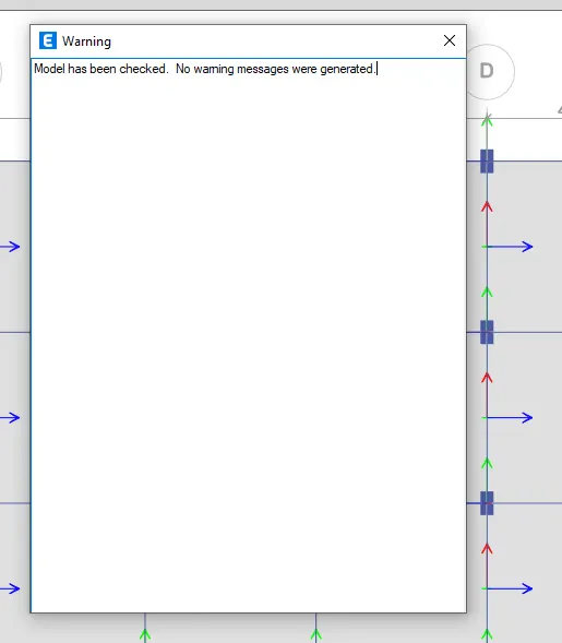
after analyzing the model the following message appears
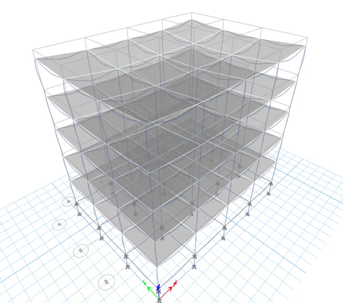
the model has been analysed
model mass participating ratio for building D
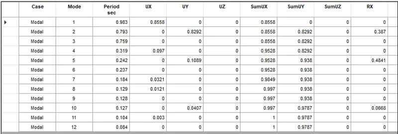
Model for building E
copy building model A
open the edit grid and story data window
edit the info in the following way
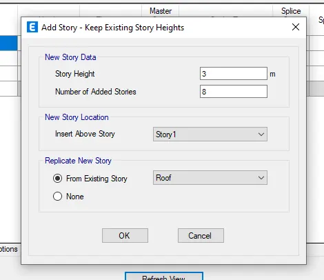
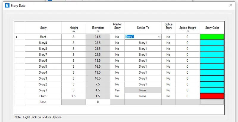
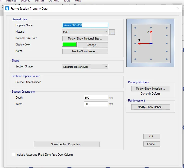
we'll create copy of column 400x400 from define tab and give new properties as column 600x600
from view tab we will set building limits as follows
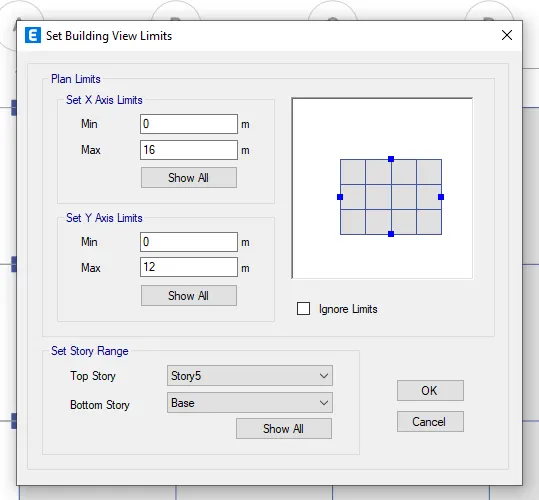
building view limit has been set
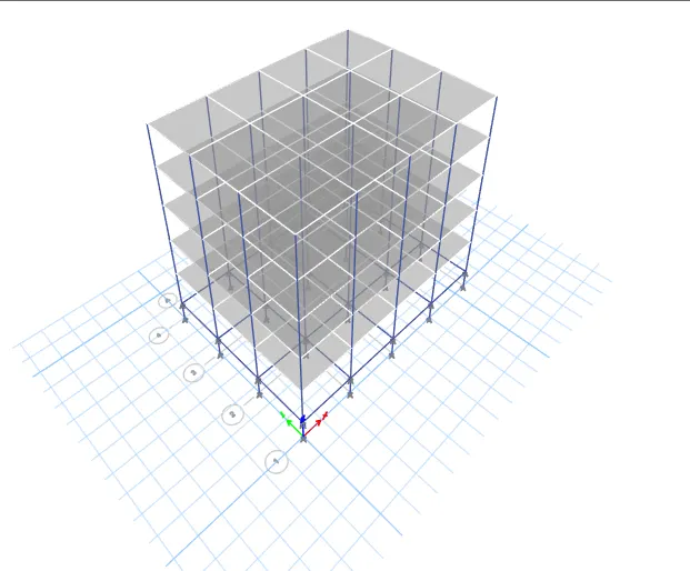
from set view option we will switch off beams, joints, floors so only columns will be visible as follows
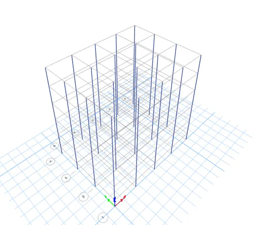
from select tab, select all the columns
from assign tab and selecting setion properties, we ill assign column size as 600x600
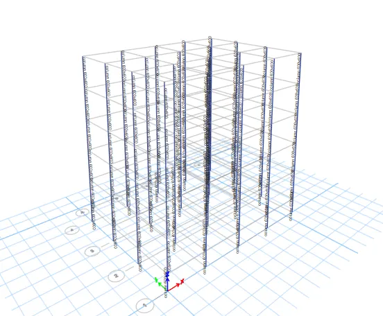
we will switch on the closed view data the result is as follows
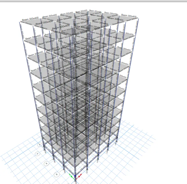
analyze the model

after running analysis
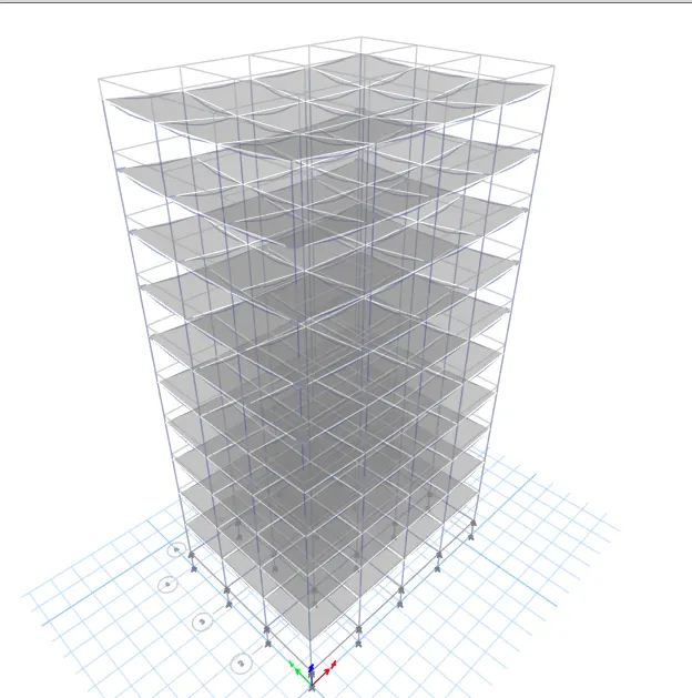
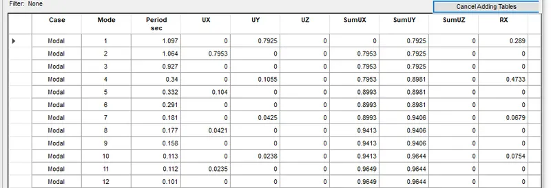
model mass participating ratios
modelling for building F
copy model E, unlock it
from edit tab then view tab
edit building views limit as follows
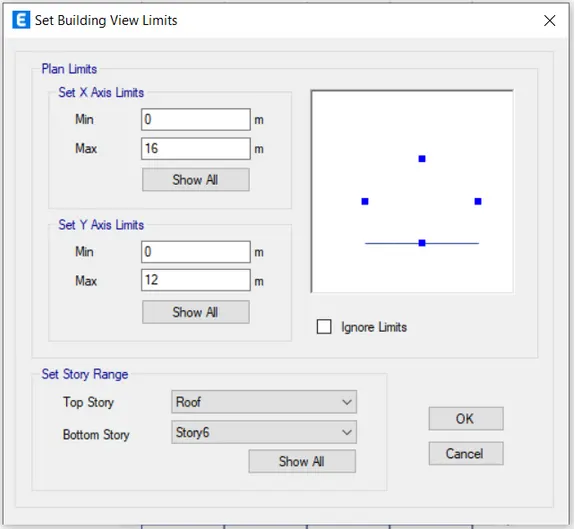
select all the columns
from the assign tab assign the columns as Column 600x600
go to view tab then building views limit
select show all and go to set diplay option
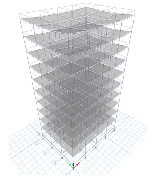
switch on beams joints floors
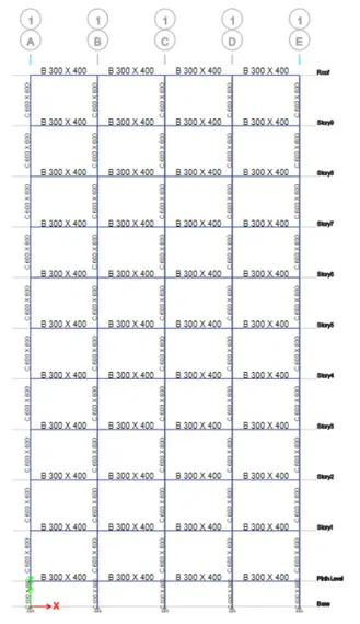
analyze the model it will give the following message

we will run analysis on the model
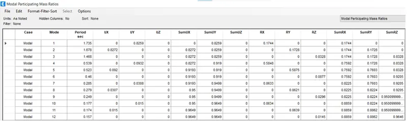
mass participating ratio for building F
Model for Building G
copy building model F
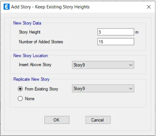
unlock it and make the changes to storys from edit tab
we will modify story data as follows
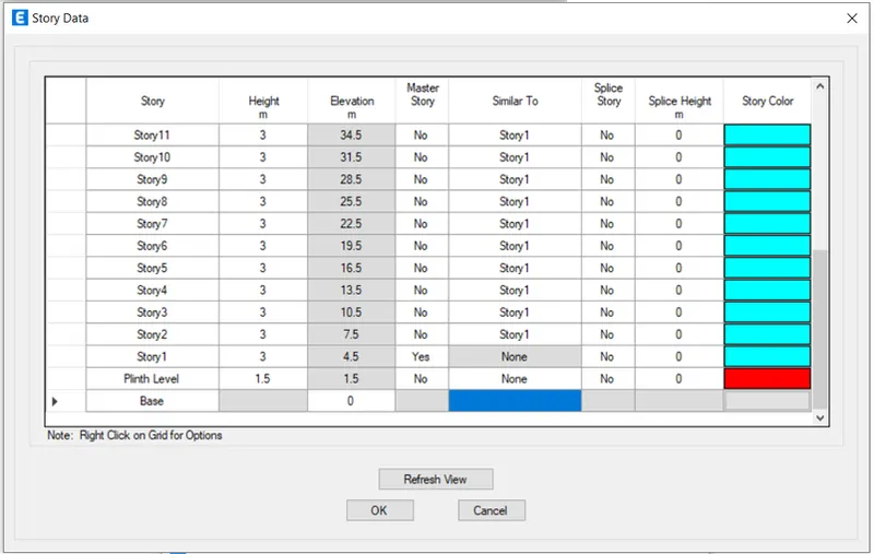
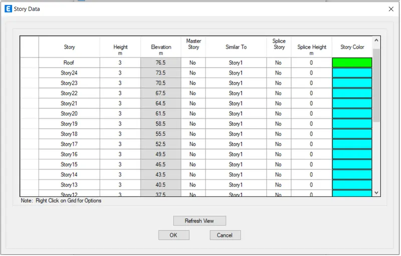
from define tab section properties
select the Column 800x800 section and copy it
make the changes as shown below
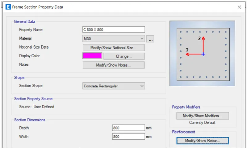
from view tab, building views limit will be set as follows
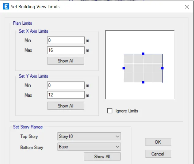
slect the columns from select tab
assign the section properties as C 800x800
it will be applied from base upto 10th floor
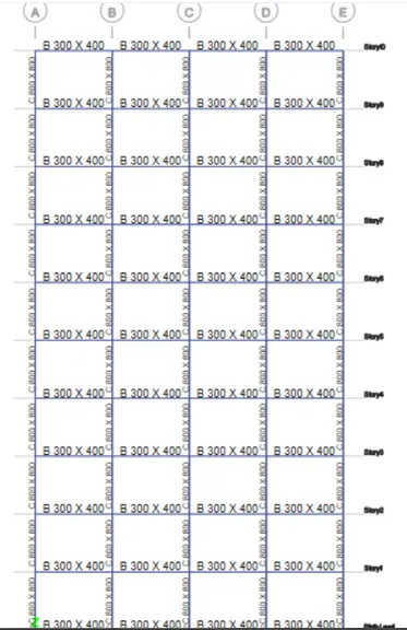
from view tab, building views will be set as follows
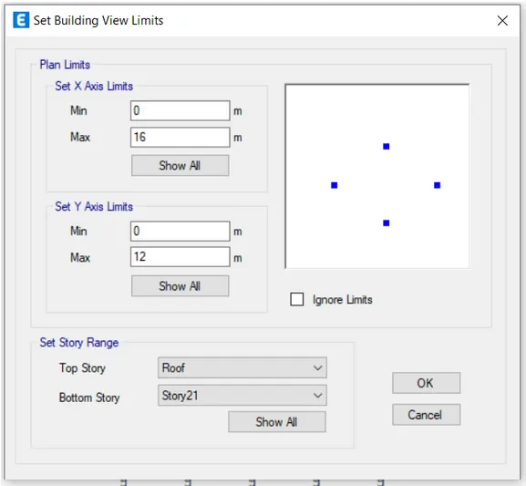
select the columns from select tab
from the assign tab, section C 400x400 properties will be applied
column will be applied from 21st story upto roof
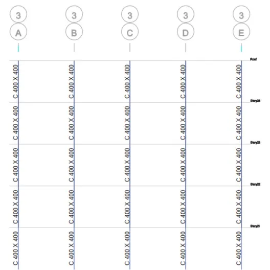
from building views limit, show all option will be enabled
beams joints and floors will be switched on now
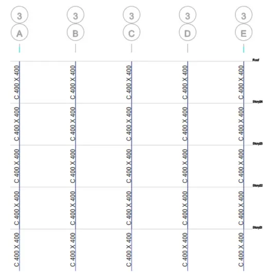
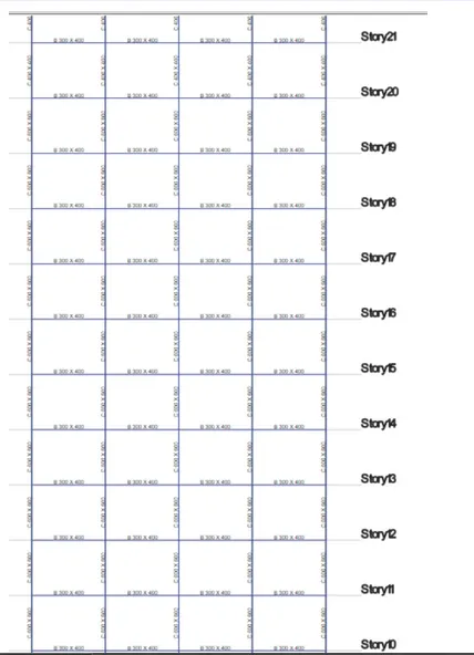
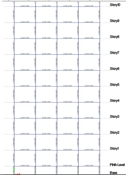
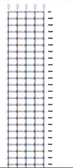
check model
from the analyze tab it will show the following results

analysis will be run on the model
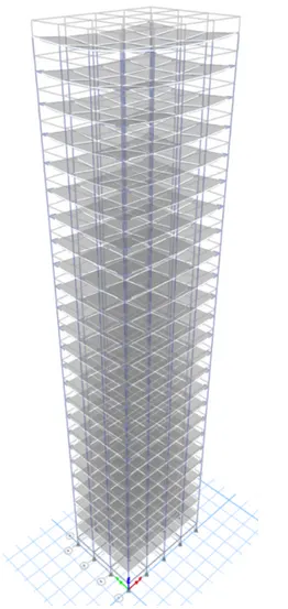
modal mass participating ratio
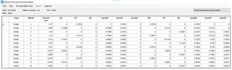
Model for building H
copy building model G
unlock the model
from view tab, building views limit will be set as follows
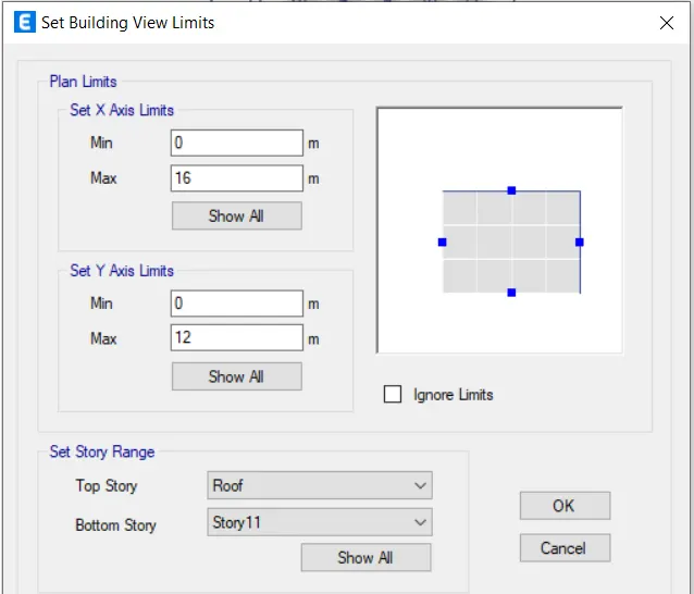
columns will be selected from select tab
and from assign tab select column 800x800
it wil be applied from 11th storey upto roof
select building views lmit
select show all
it will give the following results
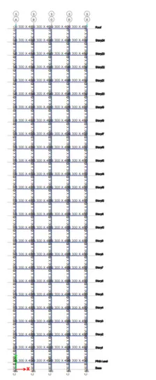
the model will be analyzed
it gives the following result

run analysis on the model
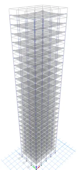
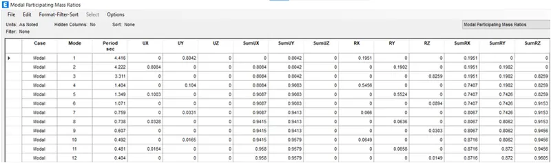
Modal mass participating ratio for building H
model for building J
copy building model H
unloack the model
select object type, select floors, hit close
we have to imposed load 10% greater than building H
go to assign, shell loads, select uniform and change data as follows
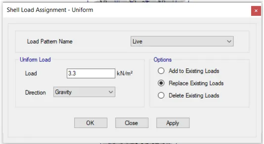
the imposed mass has been increased by 10%
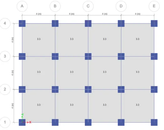
we will analyze the model

model is ready for analysis
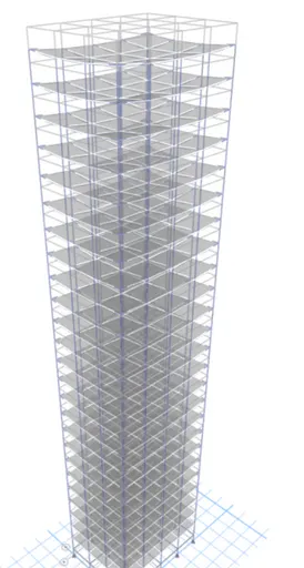
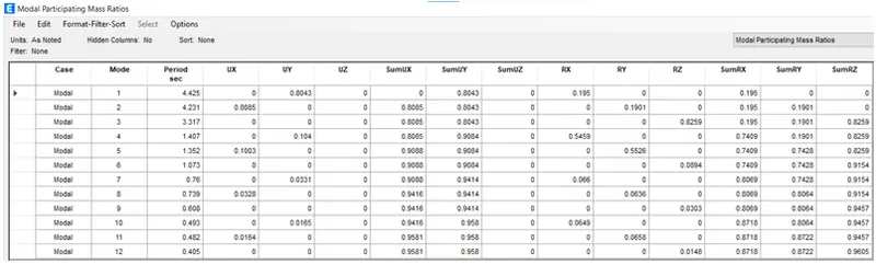
the modal mass participating ratio for building J is as follows
model for building K
we will follow same procedure for modeling new building and make some changes like assigning imposed mass 20% greater than building H
from shell loads, select uniform
and make changes as follows
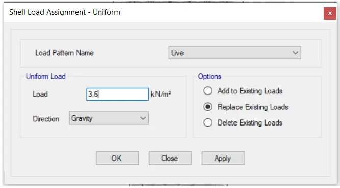
click ok and imposed mass has been increased by 20%
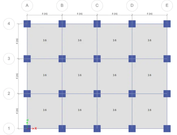
analyze the model

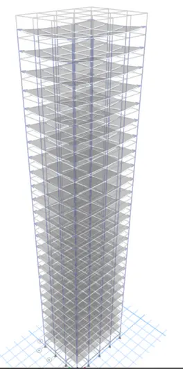
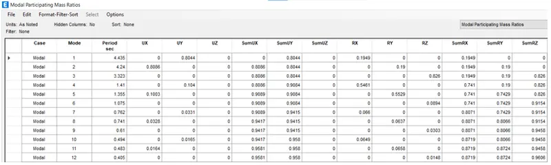
modal mass participating ratios for building K
Effect of stiffness on T
| Building E | Building F | |
| T(X1) | 1.097 | 1.735 |
| T(Y1) | 1.064 |
1.678 |
| Building G | Building H | |
| T(X1) | 4.17 | 4.416 |
| T(Y1) | 3.988 | 4.222 |
time period of building F and h is greater tham E and G because because of column uniformity in buildings F and H
effect of mass on T
comparison of natural period of building H,J and K
| H | J | K | |
| T(X1) | 4.416 | 4.425 | 4.435 |
| T(Y1) | 4.222 | 4.231 |
4.240 |
all the above buildings arehigh rise building. the only difference is that J and K has 10% and 20% more mass than building H
time period is directly proportional to mass so in J and K mass has increased
Effect of building height on T
| A | B | F | H | |
| T(x1) | 0.5 | 1.036 | 1.735 | 4.416 |
| T(Y1) | 0.488 | 1.01 | 1.678 | 4.222 |
as building height increases mass increases but overall stiffness remains same
Effect of column orientation on T
| B | C | D | |
| T(X1) | 1.036 | 1.145 | 1.12 |
| T(Y1) | 1.01 | 0.929 | 0.953 |
Factors influencing mode shape of oscillations