Projefct 1_Comparative study of different storey buildings for Seismic forces
Comparative study of different storey buildings for Seismic forces
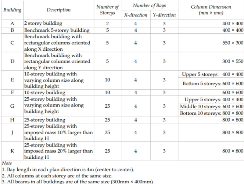
Aim:- To model and analysis of bulinding from A to K as per the datas given below and to compare the analysis of these bulidings on various parameters.
Introduction:-
- Every building has a number of natural frequencies, at which it offers minimum resistance to shaking induced by external effects and internal effects .
- Each of these natural frequencies and the associated deformation shape of a building constitute a Natural Mode of Oscillation
- The mode of oscillation with the smallest natural frequency (and largest natural period) is called the Fundamental Mode; the associated natural period T1. is called the Fundamental Natural Period.
- Regular buildings held at their base from translation in the three directions, have two fundamental translational natural periods, Txi and Ty11 associated with its horizontal translational oscillation along X and Y directions, respectively, and one fundamental rotational natural period Tel associated with its rotation about an axis parallel to Z axis.
Procedure:-
Step 1:-
- Open ETABS software.
- Select New model.
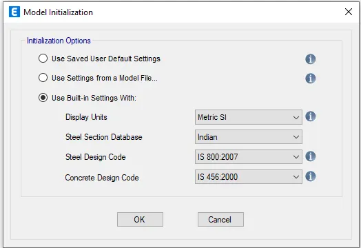
- In the window that opens select the settings as follows.
Step 2:-
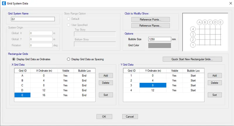
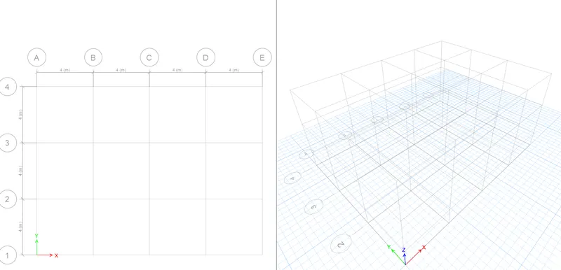
- Set the grid data systsem as follows.
- For Building A
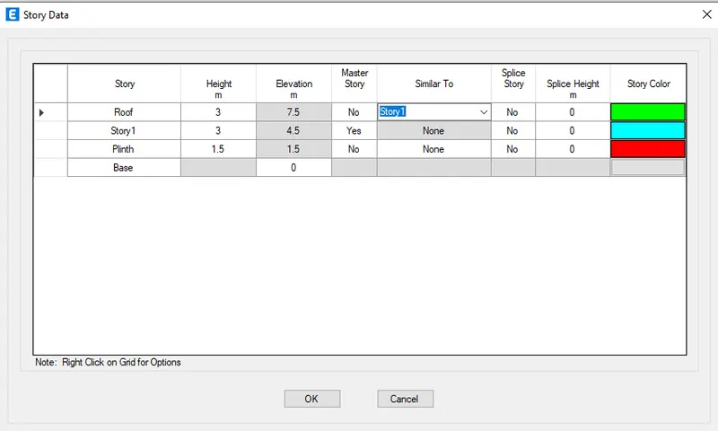
- It is a 2 Story building,Hence keep the story data as follows.
- Gives following result.
Add materials properties for the design
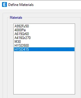
- Go to Define>Material properties.
- M30 grade concrete, rebars of strength 500 and 400 are added as shown.
Add element properties of beams,columns and slabs.
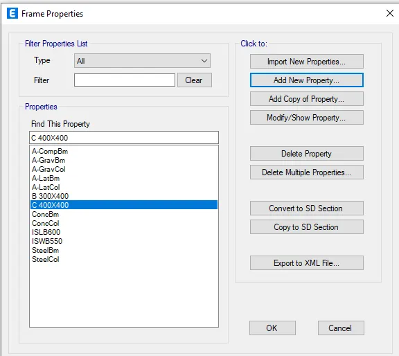
- Go to Define>section properties>frame sections
- Beam of size 300x400mm and column of size 400x400mm are added.
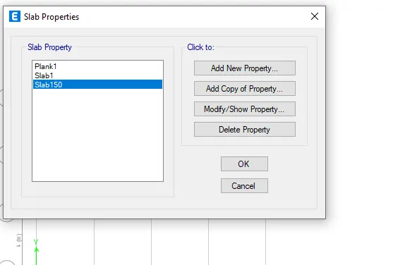
- Go to Define>section properties>slab
- Slab of thickness 150mm added
Now modelling the elements such as beams columns and slabs
- Columns are added
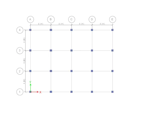
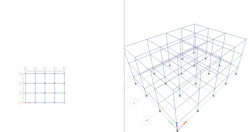
2. Beams are added.
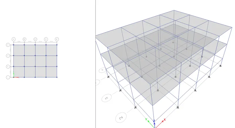
3.Slabs are added
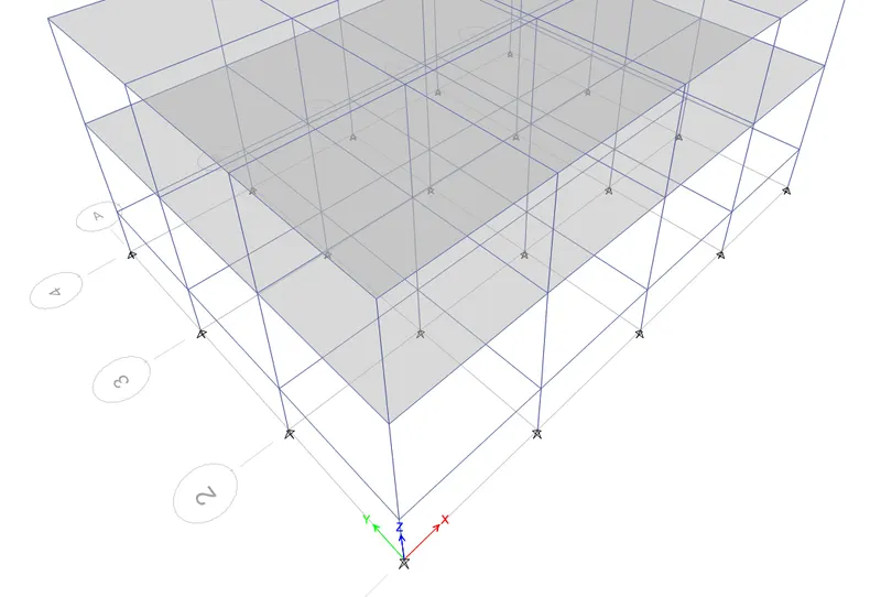
To assign the base of the building as pinned.
- Go to base plan.
- Select all base points
- Go to assign>joint>restraints
- Select the spinned in the window appears.
- Apply>ok.
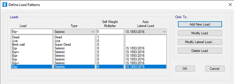
Adding load patterns
- Define>load patterns
- Add load patterns as below
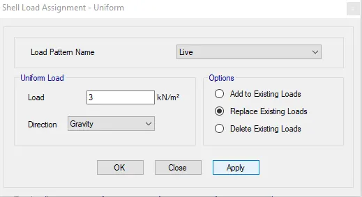
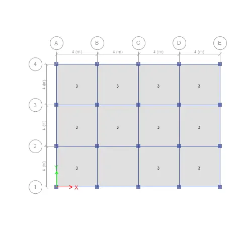
To Assign live load and wall loads
- Go to assign tab>shell loads>Uniform
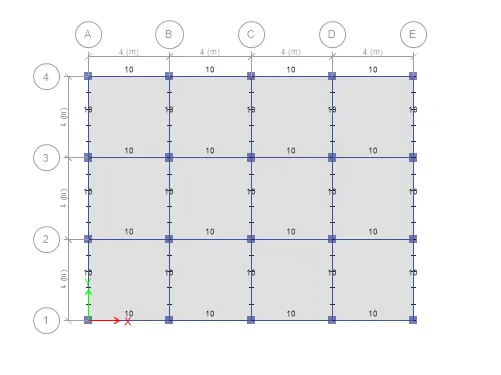
To assign Infill walls loads
- Go to assign>Frame loads>Distributed.
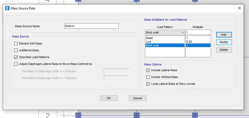
To assign mass source
- Define tab>mass source.
- Modify exixsting mass source
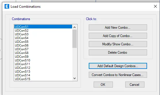
To generate load combination
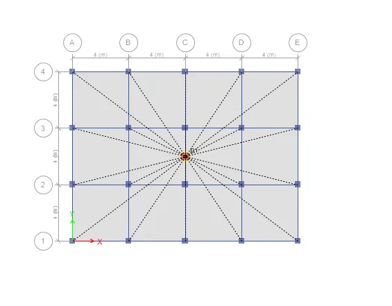
To assign diaphrams
- Select tab>Select>Object type>floor>select>close
- Assign tab>shell>diaphrams.
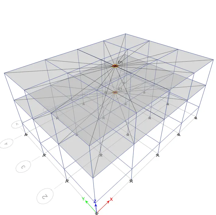
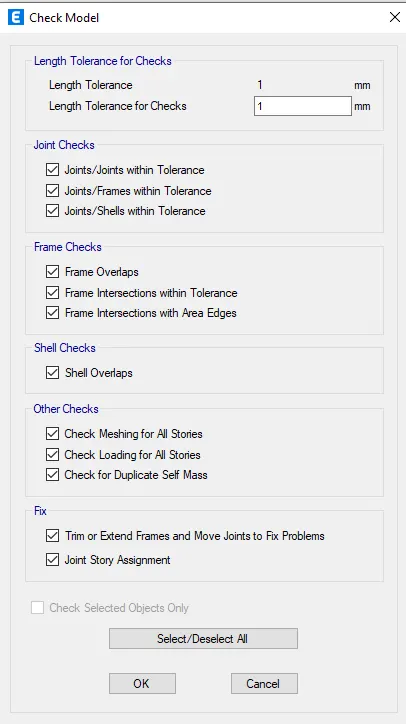
Check the model

- Run analysis
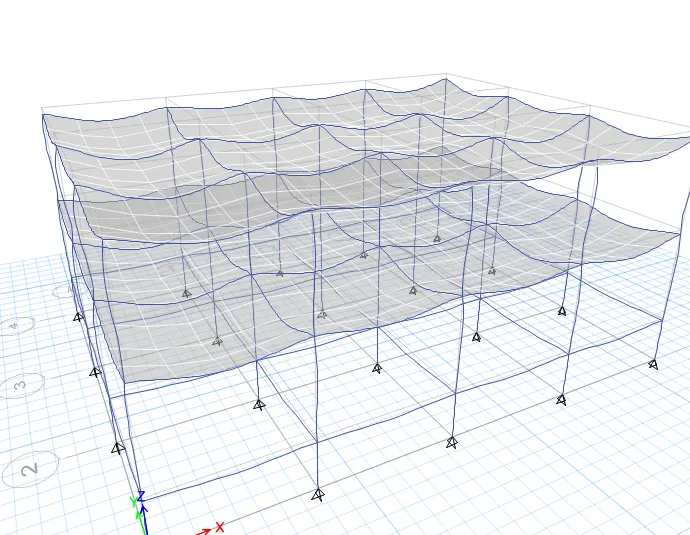
For base reactions
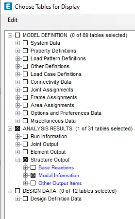
- Go to display>show tables
- In the window that appears select the settings as follows.
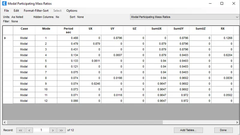
Results (Building A)
- Tx= 0.488 s
- Ty= 0.479 s
- Txy= 0.431 s
2.For Building B
- Unlock the model.
- Go to Edit>Modify/show story data
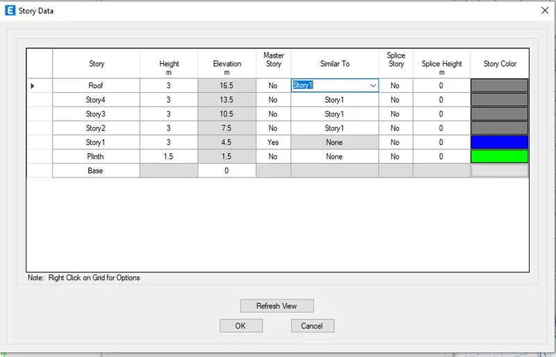
- Gives the result as follows
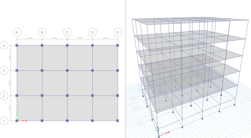
- Go to check model and follow the same procedures for the Building A

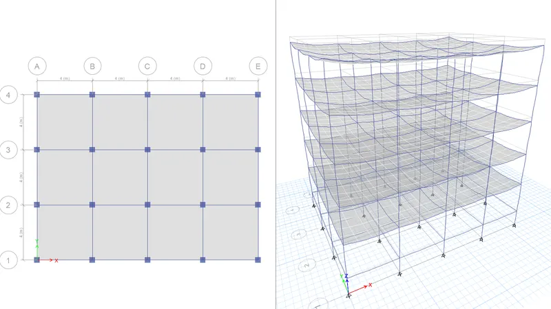
For base reactions
- Go to display>show tables
- In the window that appears select the settings as follows.
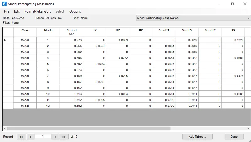
Results (Building B)
- Tx= 0.973 s
- Ty= 0.955 s
- Txy= 0.862 s
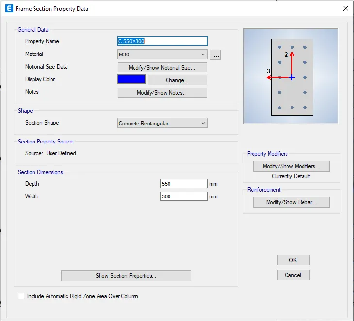
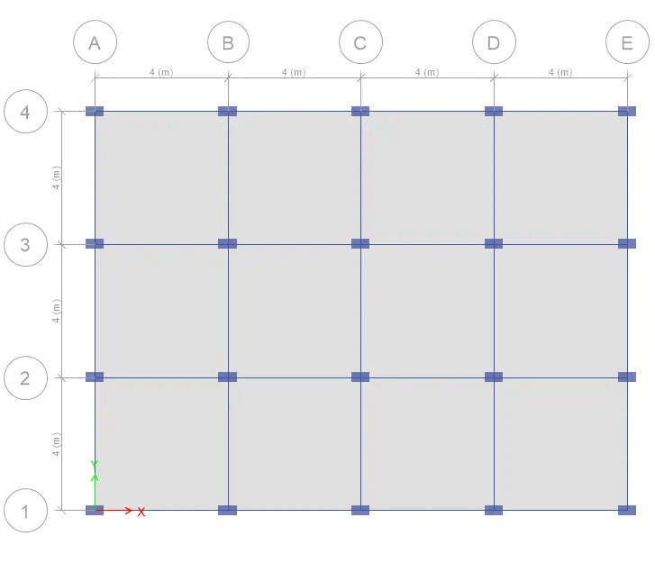
3.For Building C(5 Storey with Columns of dimension 550x300 oriented along X direction)
- Unlock the model.
- Go to define tab>section properties>Frame sections.
- Select C 400X400
- Click Copy to property.
- Set as per shown below.
- Go to select tab>select>Object type>Column.
- Then go to assign tab>section properties>select C 550x300.
- Click apply>OK.
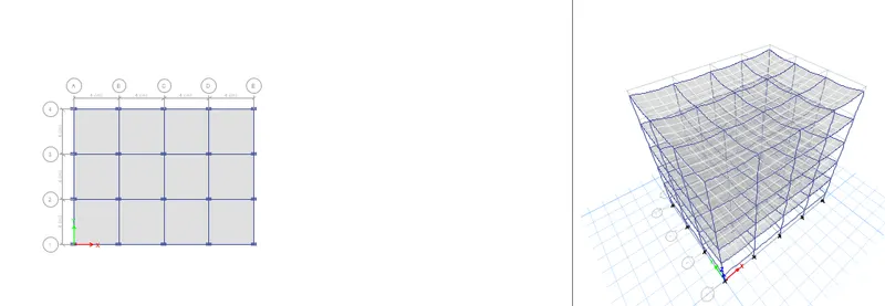
- Go to check model and follow the same procedures for the Building A

For base reactions
- Go to display>show tables
- In the window that appears select the settings as follows.
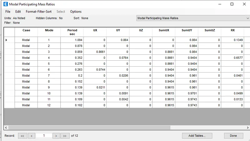
Results (Building C)
- Tx= 1.094 s
- Ty= 0.878 s
- Txy= 0.859 s
4.For Building D(5 Storey with Columns of dimension 300X550 oriented along Ydirection)
- Unlock the model.
- Go to define tab>section properties>Frame sections.
- Select Column
- Select>select>Object type>Columns.
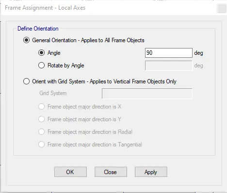
- Go to assign tab>Frame>Local axes.
- Make the settings as follows.
- Apply>ok
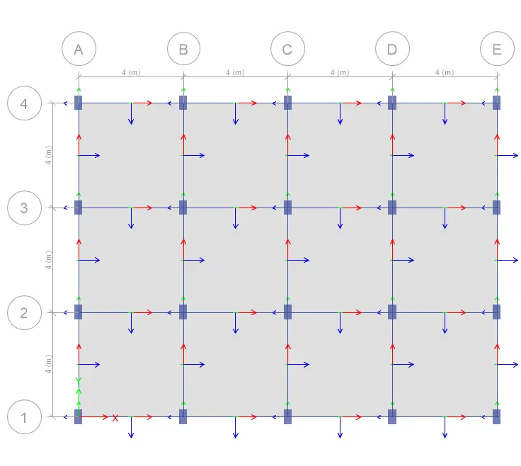
- All the columns are oreinted in Y direction.
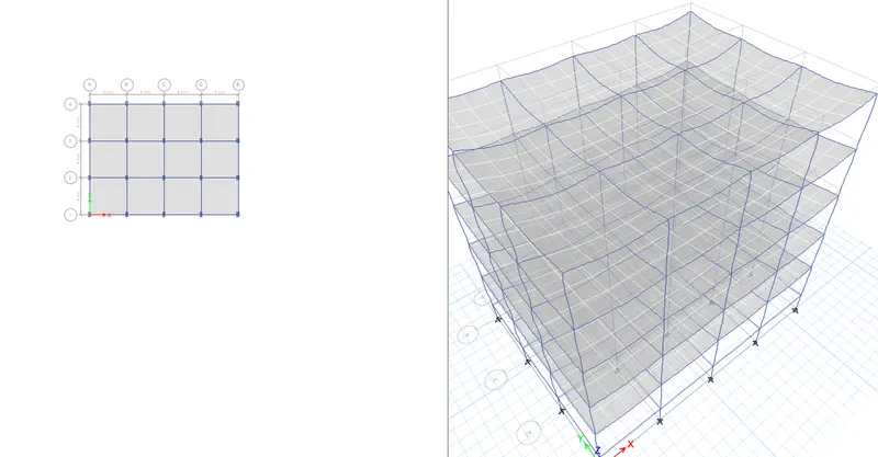
- Go to check model and follow the same procedures for the Building A

For base reactions
- Go to display>show tables
- In the window that appears select the settings as follows.
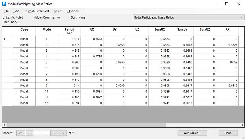
Results (Building D)
- Tx= 1.077 s
- Ty= 0.878 s
- Txy= 0.843 s
5.For Building E(10 Storey with varying Column size along Building height.)
- Unlock the model.
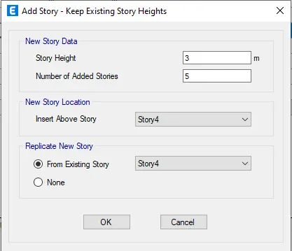
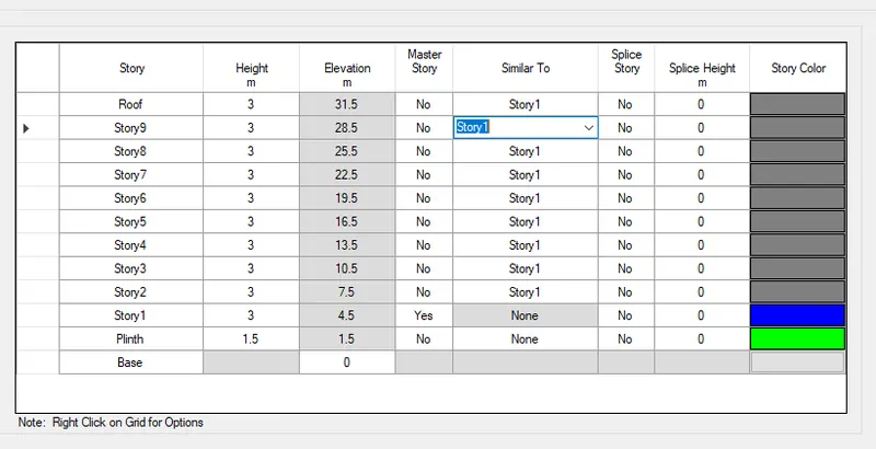
- Go to Edit>Modify/show story data
- Do the settings as follows.
- Go to define tab>Section property>Frame sections.
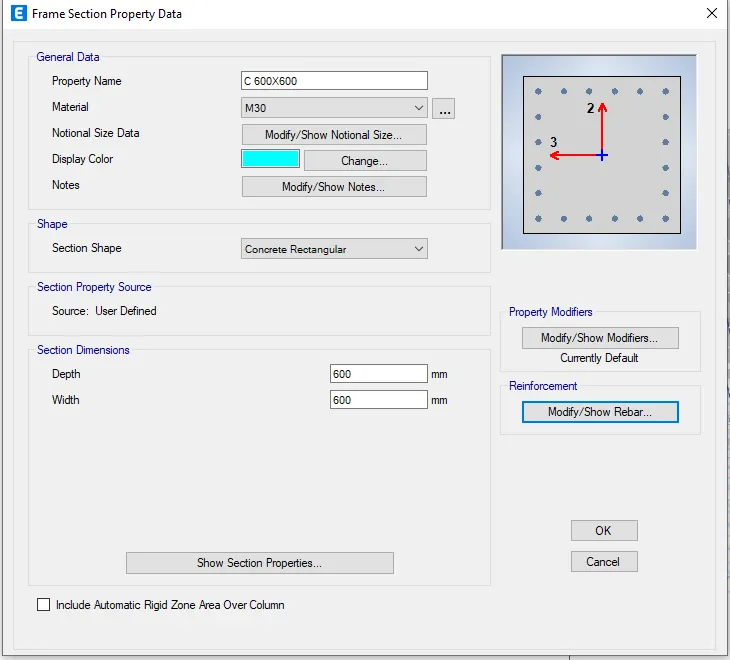
- Select C 400X400.
- Add copy to property.
- Set as per shown.
- Go to view tab.
- Select building view limit.
- Set as per shown below.
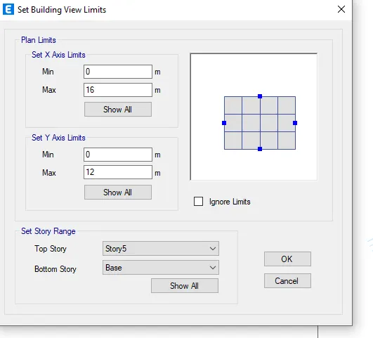
- Up to 5 story.
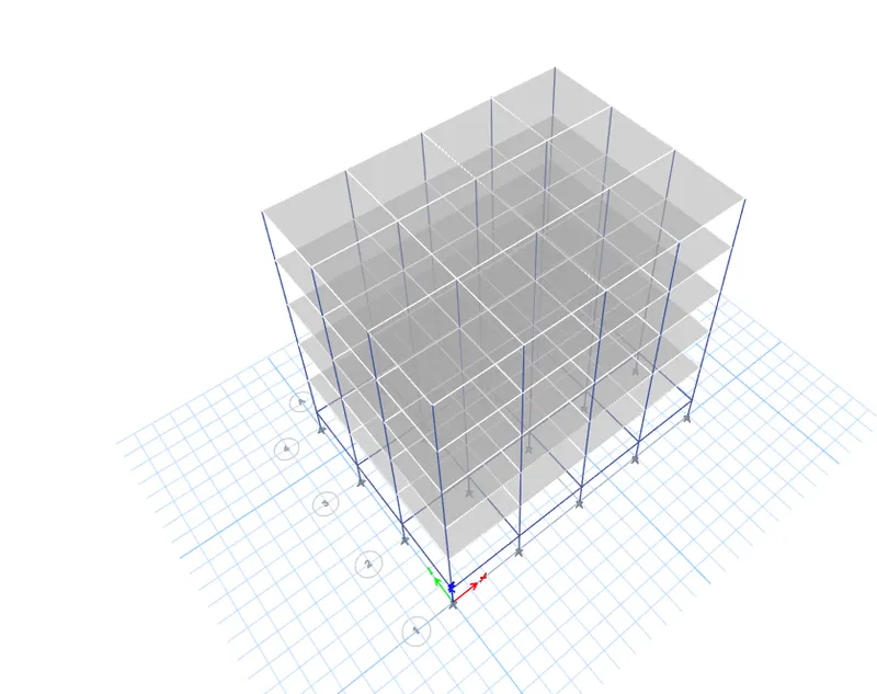
- Go toset diplay options
- Turn off beams,floors and joint restraints.
- Apply>Ok.
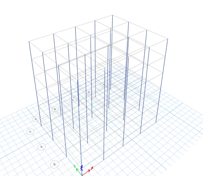
- Go to Select>select>Object type>Columns.
- Assign>Select section property.
- Select C 600x600.
- Click apply>Ok.
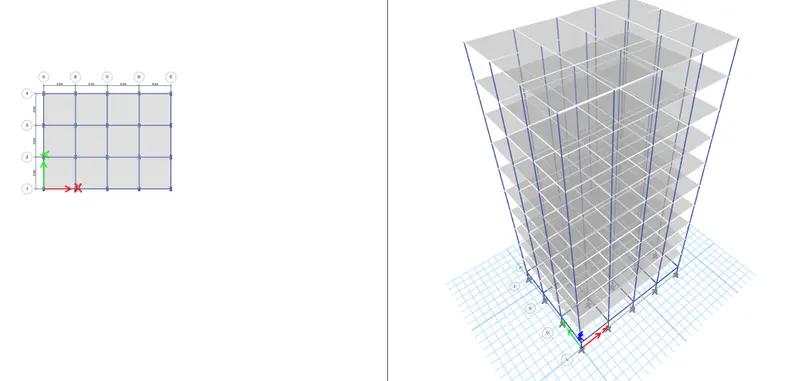
- Now the column C 600X600 is applied upto 5th floor.
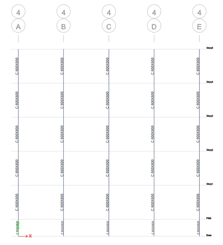
- Go to view tab
- Select> building view limit.
- Click>Show all.
- Make beams joints and floor visible.
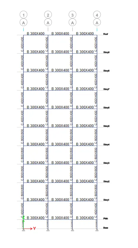
- Check moodel in the analysis tab.

- Model is ready for analysis and run analysis.
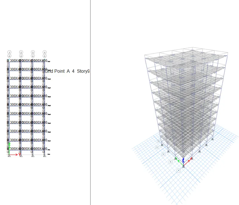
For base reactions
- Go to display>show tables
- In the window that appears select the settings as follows.
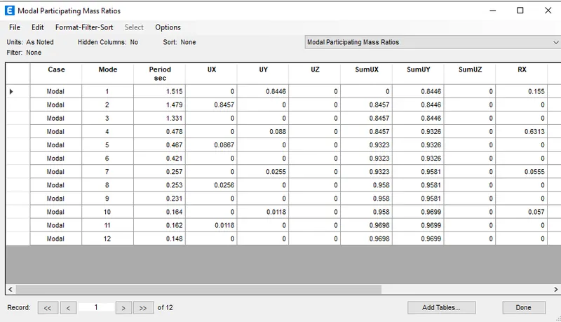
Results (Building E)
- Tx= 1.515 s
- Ty= 1.479 s
- Txy= 1.331 s
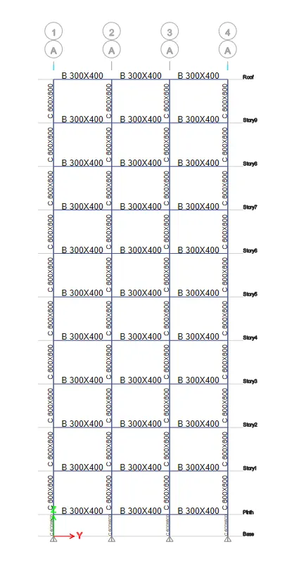
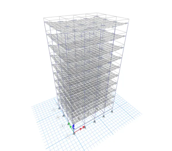
5.For Building F(10 Storey with Column size 600X600mm throughout Building height.)
- Unlock the model.
- Go to edit>View tab.
- Select building view limit.
- Set as per shown below.
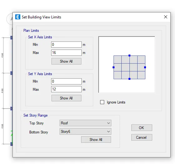

- Select all the columns form the viewed model.
- Go to assign tab>section property.
- Select C 600X600.
- click apply.
- Now the selected columns are assigned through out the model.
- Then go to View and make show all.
-
- Check moodel in the analysis tab.
- Model is ready for analysis and run analysis.
For base reactions
- Go to display>show tables
- In the window that appears select the settings as follows.
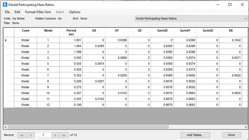
Results (Building F)
- Tx= 1.601 s
- Ty= 1.564 s
- Txy= 1.399 s
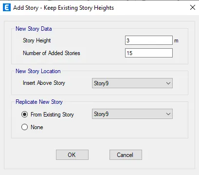
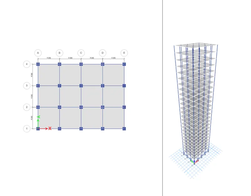
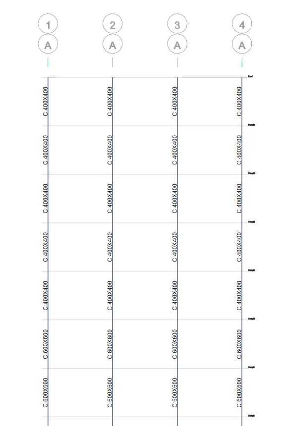
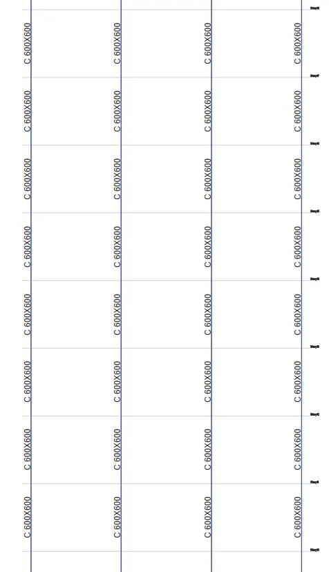
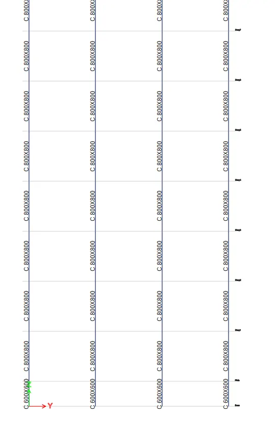
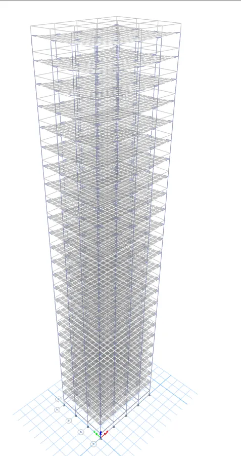
5.For Building G(25 Storey with varying Column size along Building height.)
- Unlock the model.
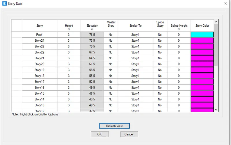
- Go to Edit>Modify/show story data
- Do the settings as follows.
- Go to define tab>Section property>Frame sections.
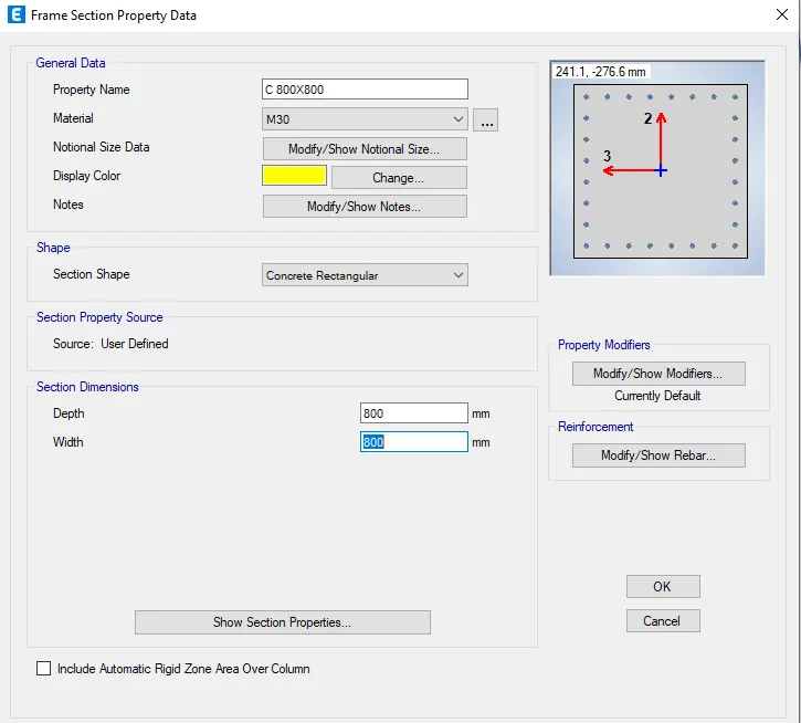
- Select C 400X400.
- Add copy to property.
- Set as per shown.
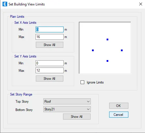
- Go to view tab>Set buliding limit.
- Do the settings as shown below.
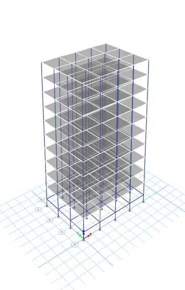
- Hide all the beams and floors by repeating the procedures in 5 and 6.
- Then select columns upto storey 10.
- Then go to assign>section properties.
- Select column C 800x800.
- Now the column C 800X800 are applied upto story 10.
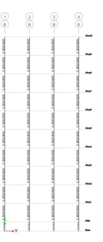
- Go to edit>View tab.
- Select building view limit.
- Set as per shown below.
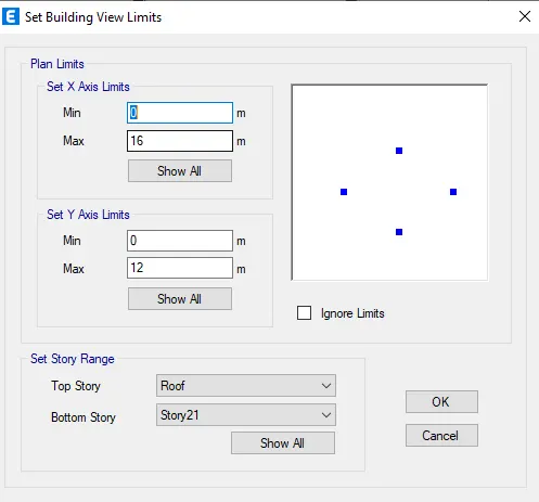
- Click ok.
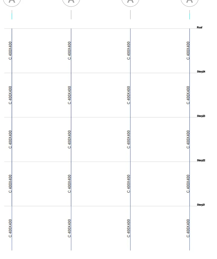
- Now change the view as show all.
- Also make beams,floors and joints vissible.
- Go to check model and follow the same procedures for the Building A
- Run analysis
For base reactions
- Go to display>show tables
- In the window that appears select the settings as follows.
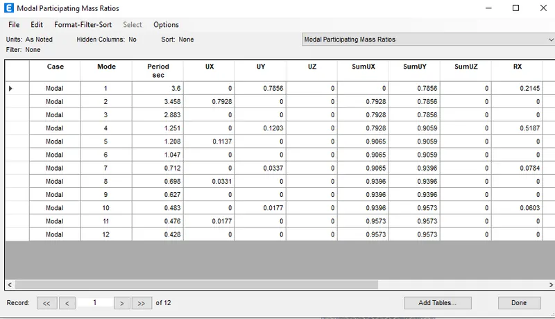
Results (Building G)
- Tx= 3.6 s
- Ty= 3.458 s
- Txy= 2.883 s
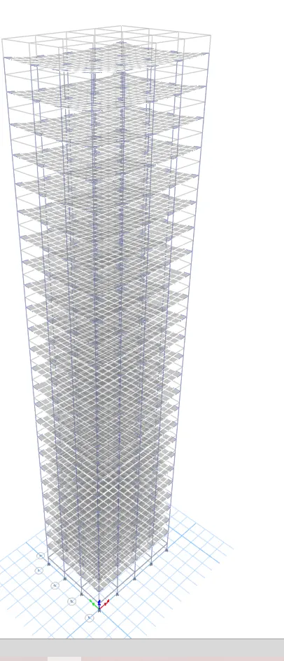
5.For Building H(25 Storey with same Column size throughout the Building height.)
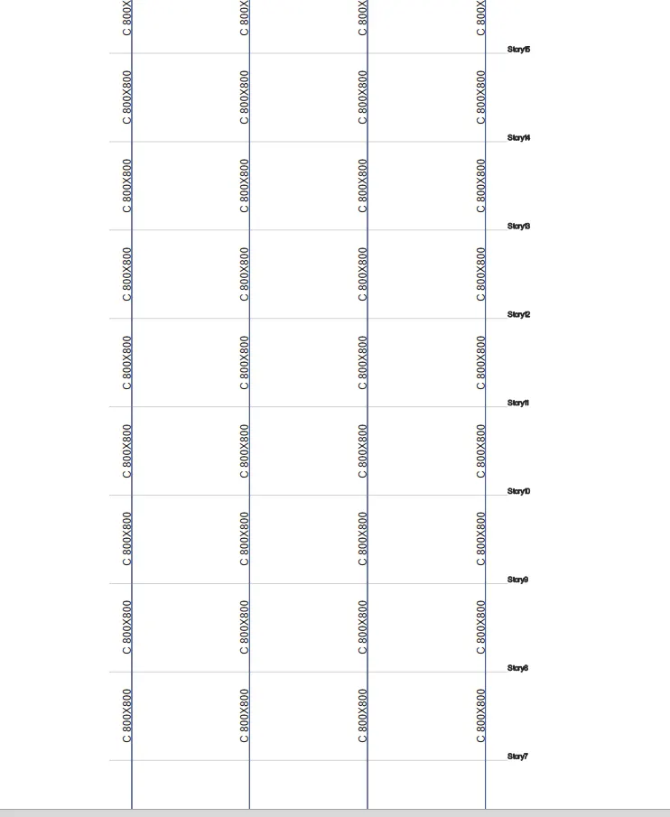
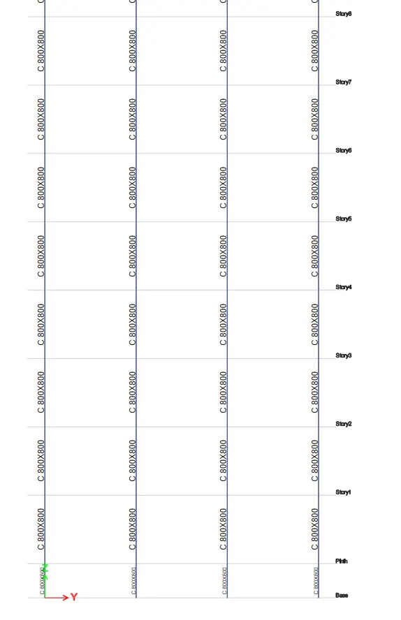
- Repeat the step by step procedures of Building F by changing column size to C 800X800 through out the height of building.
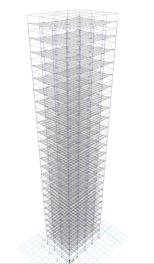
Elevation of building.
- Check the model and follow the same procedures for the Building A
- Analyse model.
For base reactions
- Go to display>show tables
- In the window that appears select the settings as follows.
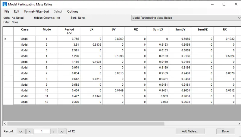
Results (Building H)
- Tx= 3.755 s
- Ty= 3.61 s
- Txy= 2.991 s
9.For Building J()
- Unlock the model H
- Set > All stories
- Go to select >Select > Object type
- Select > Floors
- Click > Close
- All the slabs are selected
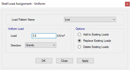
- Now as per instructions, we have to add imposed mass 10% larger than the building
- Go to assign> Shell loads
- Select > Uniform
- Set as per shown below.
- Click apply and Ok.
- Now 20% extra load is added.
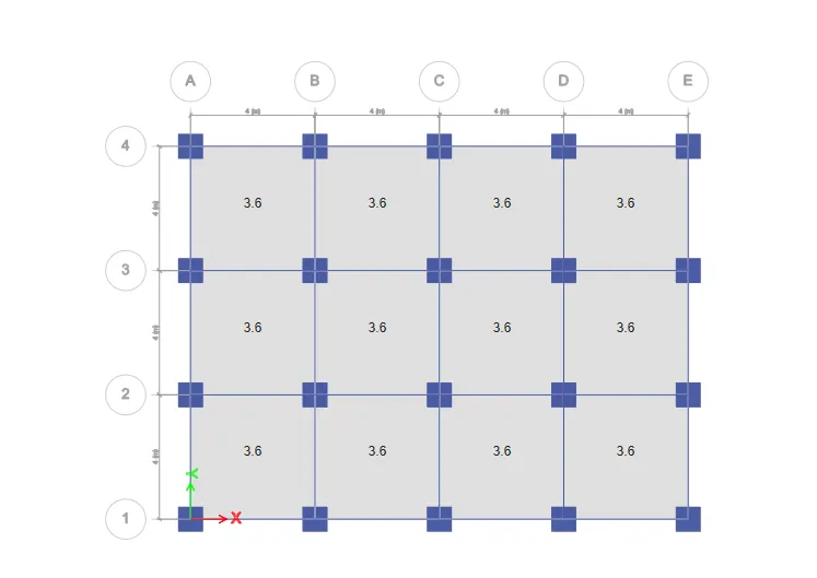
- Check the model and follow the same procedures for the Building A
- Analyse model.
For base reactions
- Go to display>show tables
- In the window that appears select the settings as follows.
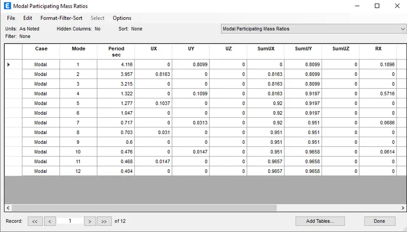
Results (Building J)
- Tx= 4.116 s
- Ty= 3.957 s
- Txy= 3.215 s
10.For Building K()
- Unlock the model H
- Set > All stories
- Go to select >Select > Object type
- Select > Floors
- Click > Close
- All the slabs are selected
- Now as per instructions, we have to add imposed mass 20% larger than the building h
- Go to assign> Shell loads
- Select > Uniform
- Set as per shown below.
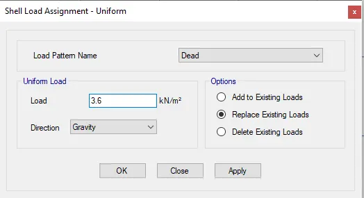
- Click>Apply>Ok.
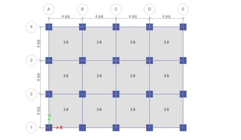
- Check the model and follow the same procedures for the Building A
- Analyse model.
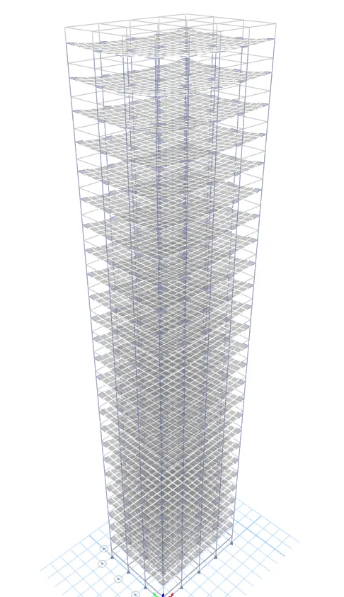
For base reactions
- Go to display>show tables
- In the window that appears select the settings as follows.
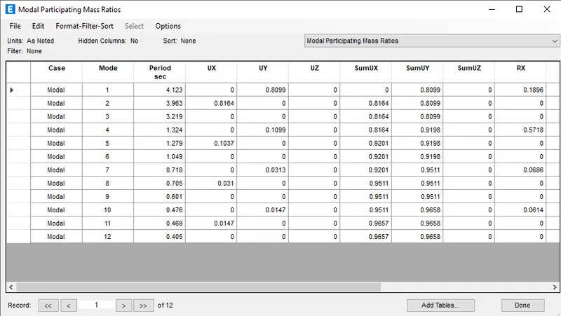
Results (Building K)
- Tx= 4.123 s
- Ty= 3.963 s
- Txy= 3.219 s
Effect of stiffness on T(E,F and G,H)
Building E and F:
Building E Building F
Tx= 1.515 s Tx= 1.601 s
Ty= 1.479 s Ty= 1.564 s
Building G and H:
Building G Building H
Tx= 3.6 s Tx= 3.755 s
Ty= 3.458 s Ty= 3.61 s
⇒ When comparing buidlings E,F and G,H, the change in time period is very less.The time period has a marginal increase for F and H.This is beacuse the column size has been maintained uniformly for both the buildings.This is beacuse the buildings E and G have lesser mass compared to F and H.Also stiffness will have least effect on these becuase as both buildings are arranged regular there won't be much shift in the centre of mass and centre of stiffness.Hence the small difference in time period of the building are mainly due to difference in mass.Because we know that Tn= 2π√(m/k).
Effect of building height on T (A,B and F,H)
Building A(2 Storey) Building B(5 Storey) Building F(10 storey) Building H(25 storey)
Tx= 0.488 s Tx= 0.973 s Tx= 1.601 s Tx= 3.755 s
Ty= 0.479 s Ty= 0.955 s Ty= 1.564 s Ty= 3.61 s
⇒ As per IS codes the the height of the building and time period is obtained by the equation T= 0.09h/d܂.Hence the the time period increases as the height increases.And here we can see that the building follows the trend as per IS CODE.
Effect of column orientation on T(comparing B,C and D)
Building B(SQUARE COLUMNS) Building C(C 550X300) Building D(C 300X550)
Tx= 0.973 s Tx= 1.094 s Tx= 1.077 s
Ty= 0.955 s Ty= 0.878 s Ty= 0.878 s
Txy=0.862 s Txy= 0.859 s Txy= 0.843 s
⇒ As the columns in Building B are squares, it will have almost equal time periods in both direction.Here in etabs result also the time periods are almost equal.
⇒ The longer edge of columns are arranged in X direction in shorter edge in Y direction in the building C .So time period in X direction have to be obtained as lesser than that of Y direction as in X direction it will be more stiffer.
⇒ The longer edge of columns are arranged in Y direction in shorter edge in X direction in the building D.So time period in Y direction have to be obtained as lesser than that of X direction as in Y direction it will be more stiffer.
Effect of flexural stiffness of structural shapes on modal shapes.
Comparing the fundamental mode shapes of the building B in two situations:
- For the original building B.
- For the building B with flexural stiffness very small compared to the original building.
So, for this we need to develop another model B with lesser flexural stiffness of beam. In this model the moment of inertia about the 2 and 3 axis is changed to 0.1.
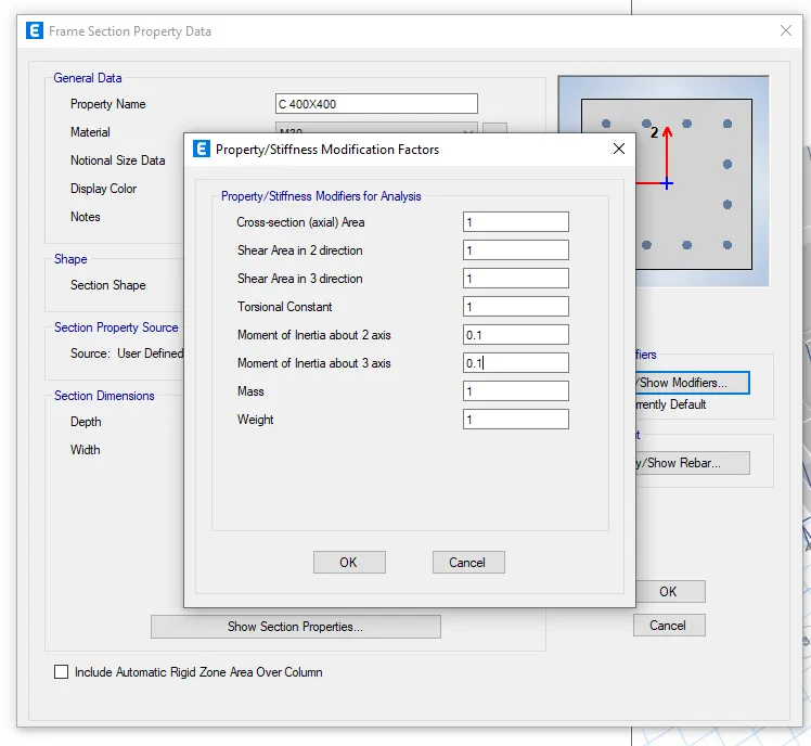
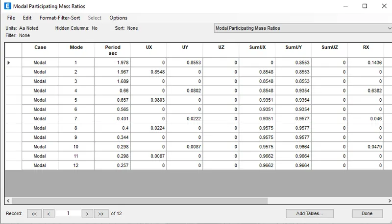
Building B (Normal case) Building B (special case with lesser flexural stifnnes)
Tx= 0.973 s Tx = 1.978 s
Ty= 0.955 s Ty = 1.967 s
Txy=0.862 s Txy=1.689 s
Here the etabs analysis result shows that the time period has a conciderable increase when the flexural stiffness was reduced. We know that the stiffness and the time period has an inverse relationship.This is because the when we reduce the flexural stifness the buiding become more flexible and leads to increase in time period in a siesmic activity.
Effect of Axial stiffness of vertical members on mode shapes.
Comparing the mode shape of building H in two situation:
- Original building H
- When axial cross sectional area of the column is reduced by a factor of 0.1.
For this we need to develop another model H with smaller axial cross section of column.
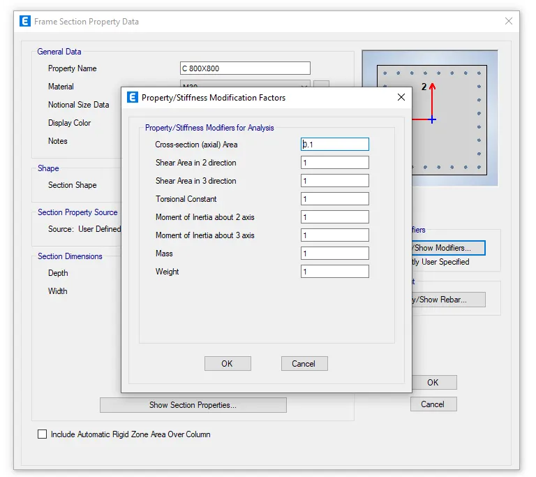
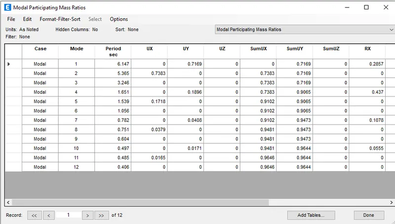
Building H (Normal case) Building H (with smaller axial cross section)
Tx= 3.755 s Tx = 6.147 s
Ty= 3.61 s Ty = 5.365 s
Txy= 2.991 s Txy = 3.246
Here we can see the increase in Time period is increasing as the axial cross section reduced.where rotation has least effect in changing axial cross section.
Effect of Degree of fixidity at column bases on mode shape:
Comparing the mode shape of building B in two situation:
- Original building B when the base is pinned
- Another model of the building B, when the base of the column is fixed.
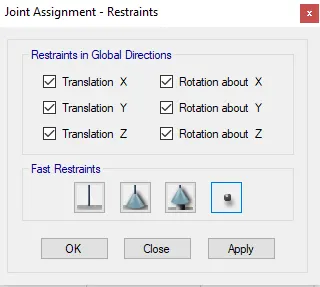
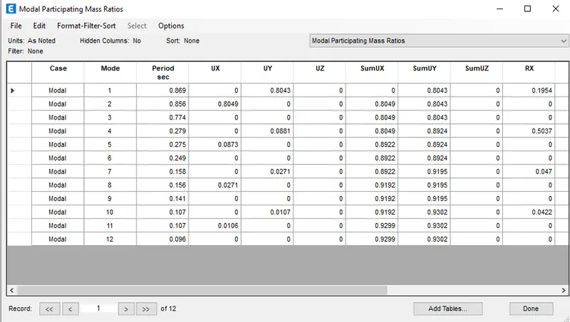
Building B (Normal case) Building B (special case with Fixed end at the base)
Tx= 0.973 s Tx = 0.869 s
Ty= 0.955 s Ty = 0.856 s
Txy=0.862 s Txy=0.774 s
⇒Here the Time period reduced when fixed end replaced by pinned base. This is why beacause we know that fixed end support is more rigid than that of pinned.Hence the time period has reduced for fixed than that of pinned end.
Result:-
All the 10 building models From A to K have analyised and all the suggested comparison study has been done.