Projefct 1_Comparative study of different storey buildings for Seismic forces
Comparing the different parameters of structure.
ANSWER
Structure – A:
- Open the new model.
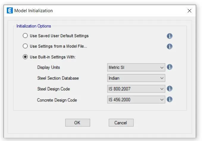
- Set the units at Indian parameters.
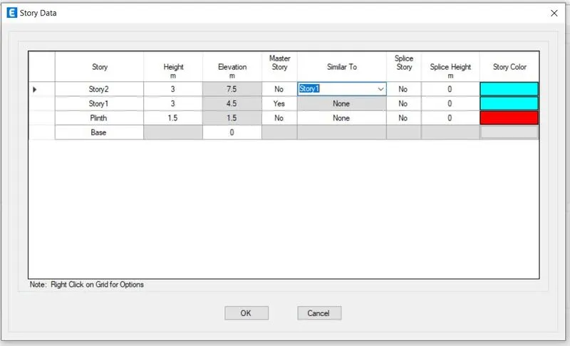
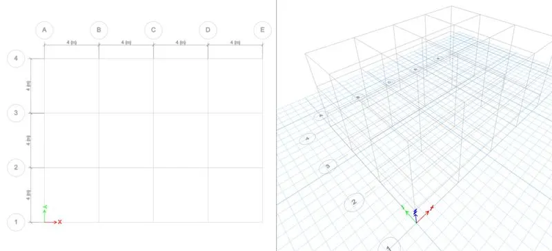
- Next to prepare the story and Grids formation.
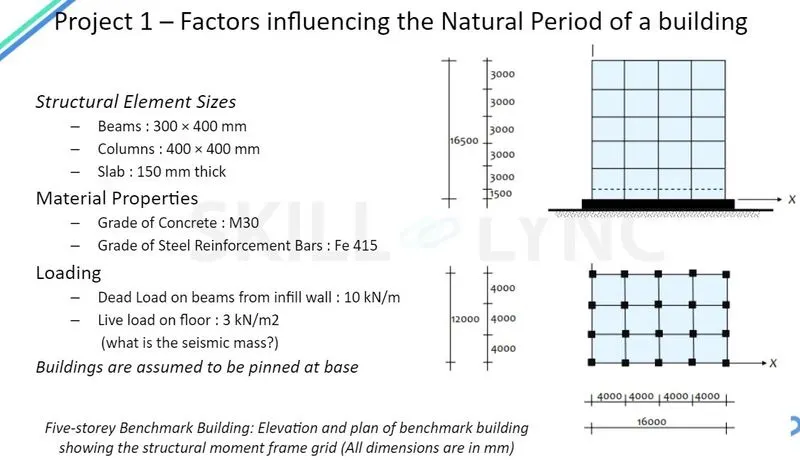
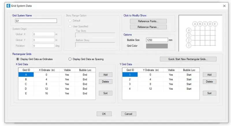
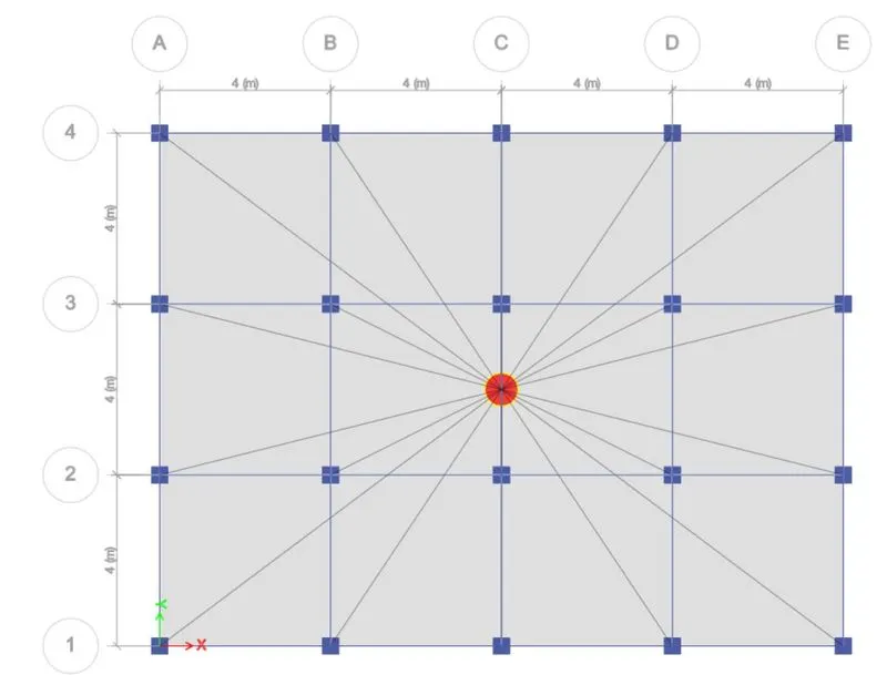
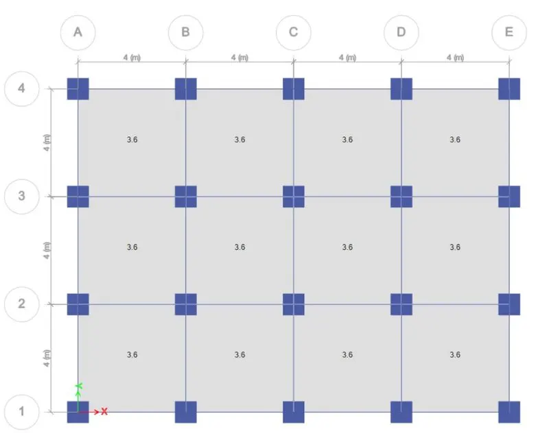
- The grids spacing at 4m in X direction(4 bays) and 4m in Y direction(3 bays).
- To add the material properties of concrete in M30.
- Rebars in HYSD415.
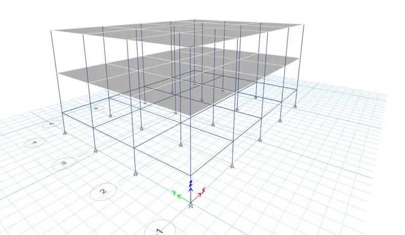
- The beam size is 300mm x 400mm
- The column size is 400mm x 400mm at all stories.
- The slab thickness is 150mm thick.
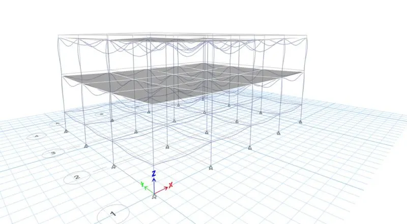
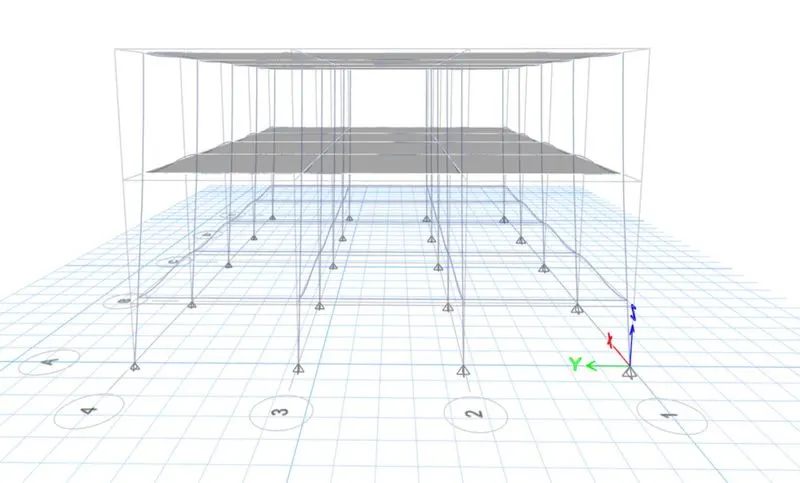
- This structure is framed by 2 story building and each story height is 3m.
- To add the loads and set the load patterns of dead, live and earthquake(seismic) load.
- The live load is 3 KN/m^2.
- The brickwall infill is 10KN/m.
- Then, to Assign the mass properties, Load combinations, diaphragms, modal analysis.
- After that, to check the model and RUN the analysis.
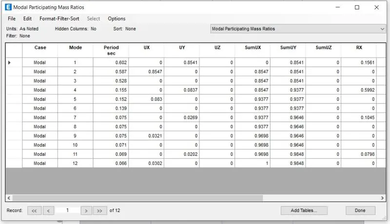
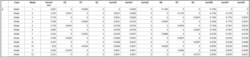
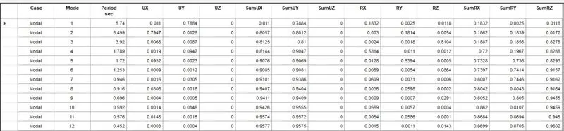
- Next to get the data of TIME PERIOD and MODE SHAPES at 12 stages.
- For choosing, DISPLAY > show tables.
Structure – B:
- Open the new model.
- Set the units at Indian parameters.
- Next to prepare the story and Grids formation.
- The grids spacing at 4m in X direction(4 bays) and 4m in Y direction(3 bays).
- To add the material properties of concrete in M30.
- Rebars in HYSD415.
- The beam size is 300mm x 400mm
- The column size is 400mm x 400mm at all stories.
- The slab thickness is 150mm thick.
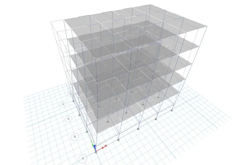
- This structure is framed by 5 story building and each story height is 3m.
- To add the loads and set the load patterns of dead, live and earthquake(seismic) load.
- The live load is 3 KN/m^2.
- The brickwall infill is 10KN/m.
- Then, to Assign the mass properties, Load combinations, diaphragms, modal analysis.
- After that, to check the model and RUN the analysis.
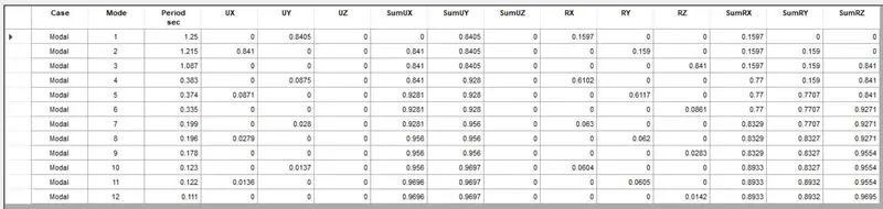
- Next to get the data of TIME PERIOD and MODE SHAPES at 12 stages.
- For choosing, DISPLAY > show tables.
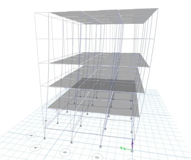
Structure – C:
- Open the new model.
- Set the units at Indian parameters.
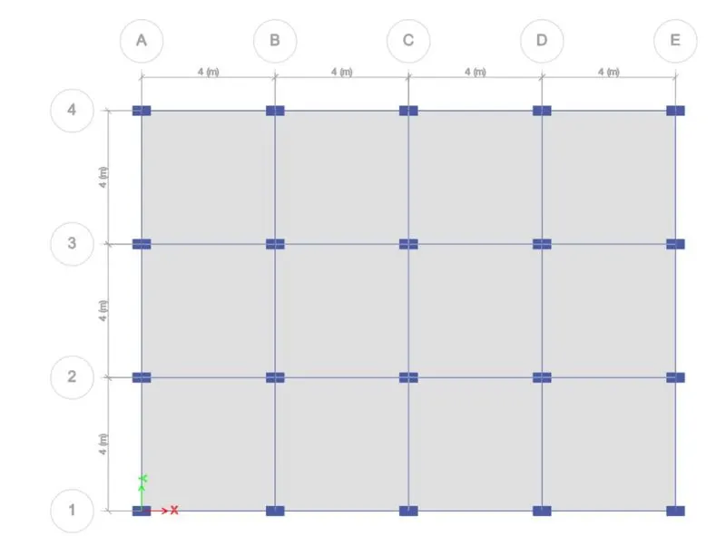
- Next to prepare the story and Grids formation.
- The grids spacing at 4m in X direction(4 bays) and 4m in Y direction(3 bays).
- To add the material properties of concrete in M30.
- Rebars in HYSD415.
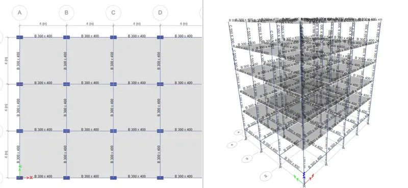
- The beam size is 300mm x 400mm
- The column size is 550mm x 350mm at all stories.
- The column was oriented along X dierection.
- The slab thickness is 150mm thick.
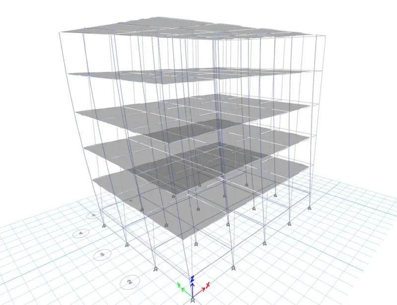
- This structure is framed by 5 story building and each story height is 3m.
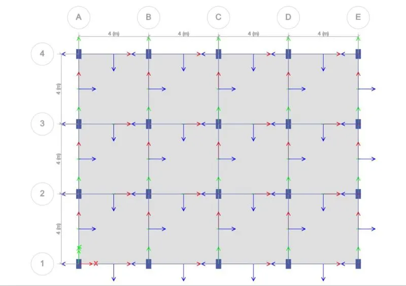
- To add the loads and set the load patterns of dead, live and earthquake(seismic) load.
- The live load is 3 KN/m^2.
- The brickwall infill is 10KN/m.
- Then, to Assign the mass properties, Load combinations, diaphragms, modal analysis.
- After that, to check the model and RUN the analysis.
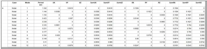
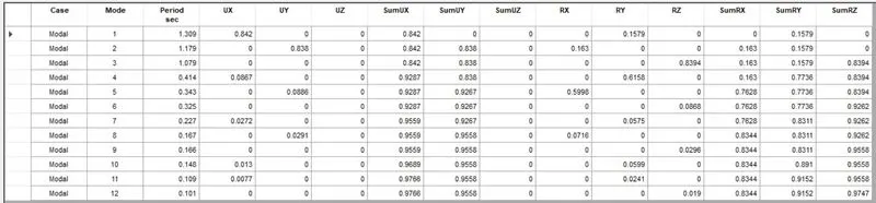
- Next to get the data of TIME PERIOD and MODE SHAPES at 12 stages.
- For choosing, DISPLAY > show tables.
Structure – D:
- Open the new model.
- Set the units at Indian parameters.
- Next to prepare the story and Grids formation.
- The grids spacing at 4m in X direction(4 bays) and 4m in Y direction(3 bays).
- To add the material properties of concrete in M30.
- Rebars in HYSD415.
- The beam size is 300mm x 400mm
- The column size is 300mm x 550mm at all stories.
- The column was oriented along y dierection.
- The slab thickness is 150mm thick.
- This structure is framed by 5 story building and each story height is 3m.
- To add the loads and set the load patterns of dead, live and earthquake(seismic) load.
- The live load is 3 KN/m^2.
- The brickwall infill is 10KN/m.
- Then, to Assign the mass properties, Load combinations, diaphragms, modal analysis.
- After that, to check the model and RUN the analysis.
- Next to get the data of TIME PERIOD and MODE SHAPES at 12 stages.
- For choosing, DISPLAY > show tables.
Structure – E:
- Open the new model.
- Set the units at Indian parameters.
- Next to prepare the story and Grids formation.
- The grids spacing at 4m in X direction(4 bays) and 4m in Y direction(3 bays).
- To add the material properties of concrete in M30.
- Rebars in HYSD415.
- The beam size is 300mm x 400mm
- The Columns are varying size along building height for
- upper 5 Storeys column size is 400mm x 400mm.
- Bottom 5 storeys column size is 600mm x 600mm.
- The slab thickness is 150mm thick.
- This structure is framed by 10 story building and each story height is 3m.
- To add the loads and set the load patterns of dead, live and earthquake(seismic) load.
- The live load is 3 KN/m^2.
- The brickwall infill is 10KN/m.
- Then, to Assign the mass properties, Load combinations, diaphragms, modal analysis.
- After that, to check the model and RUN the analysis.
- Next to get the data of TIME PERIOD and MODE SHAPES at 12 stages.
- For choosing, DISPLAY > show tables.
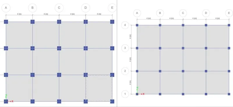
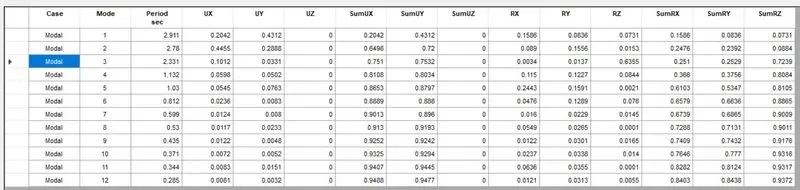
Structure – F:
- Open the new model.
- Set the units at Indian parameters.
- Next to prepare the story and Grids formation.
- The grids spacing at 4m in X direction(4 bays) and 4m in Y direction(3 bays).
- To add the material properties of concrete in M30.
- Rebars in HYSD415.
- The beam size is 300mm x 400mm
- The Columns Size is 600mm x 600mm.
- The slab thickness is 150mm thick.
- This structure is framed by 10 story building and each story height is 3m.
- To add the loads and set the load patterns of dead, live and earthquake(seismic) load.
- The live load is 3 KN/m^2.
- The brickwall infill is 10KN/m.
- Then, to Assign the mass properties, Load combinations, diaphragms, modal analysis.
- After that, to check the model and RUN the analysis.
- Next to get the data of TIME PERIOD and MODE SHAPES at 12 stages.
- For choosing, DISPLAY > show tables.
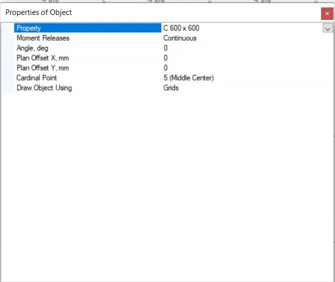
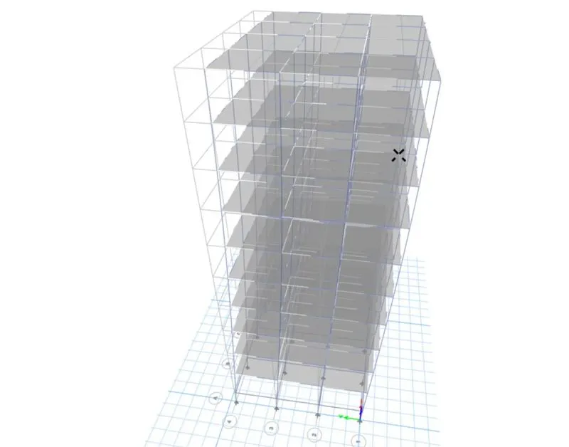
Structure – G:
- Open the new model.
- Set the units at Indian parameters.
- Next to prepare the story and Grids formation.
- The grids spacing at 4m in X direction(4 bays) and 4m in Y direction(3 bays).
- To add the material properties of concrete in M30.
- Rebars in HYSD415.
- The beam size is 300mm x 400mm
- The Columns are varying size along building height for
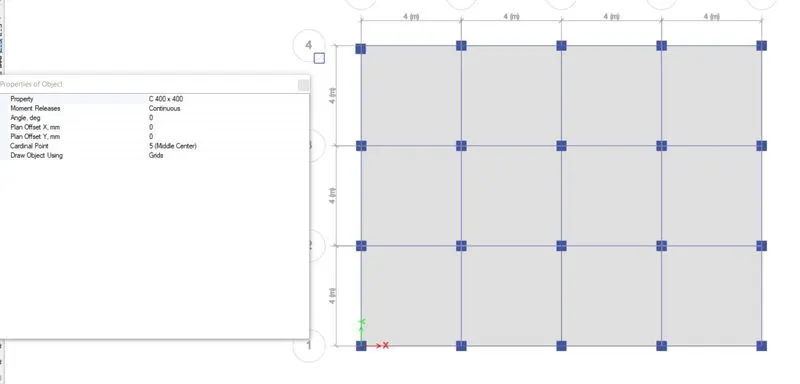
- upper 5 Storeys column size is 400mm x 400mm.
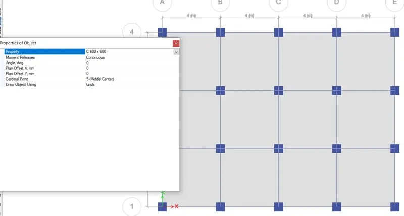
- Middle 10 storeys column size is 600mm x 600mm
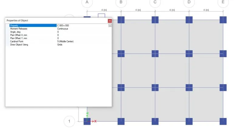
-Bottom 10 storeys column size is 800mm x 800mm.
- The slab thickness is 150mm thick.
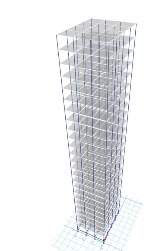
- This structure is framed by 25 story building and each story height is 3m.
- To add the loads and set the load patterns of dead, live and earthquake(seismic) load.
- The live load is 3 KN/m^2.
- The brickwall infill is 10KN/m.
- Then, to Assign the mass properties, Load combinations, diaphragms, modal analysis.
- After that, to check the model and RUN the analysis.
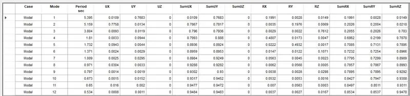
- Next to get the data of TIME PERIOD and MODE SHAPES at 12 stages.
- For choosing, DISPLAY > show tables.
Structure – H:
- Open the new model.
- Set the units at Indian parameters.
- Next to prepare the story and Grids formation.
- The grids spacing at 4m in X direction(4 bays) and 4m in Y direction(3 bays).
- To add the material properties of concrete in M30.
- Rebars in HYSD415.
- The beam size is 300mm x 400mm
- The Columns Size is 800mm x 800mm.
- The slab thickness is 150mm thick.
- This structure is framed by 25 story building and each story height is 3m.
- To add the loads and set the load patterns of dead, live and earthquake(seismic) load.
- The live load is 3 KN/m^2.
- The brickwall infill is 10KN/m.
- Then, to Assign the mass properties, Load combinations, diaphragms, modal analysis.
- After that, to check the model and RUN the analysis.
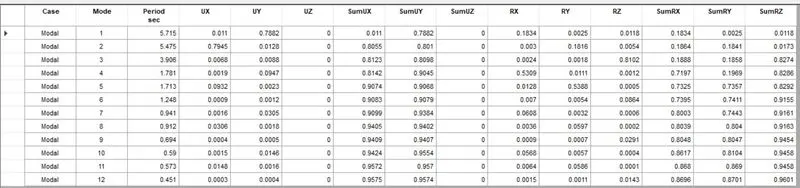
- Next to get the data of TIME PERIOD and MODE SHAPES at 12 stages.
- For choosing, DISPLAY > show tables.
Structure – J:
- Open the new model.
- Set the units at Indian parameters.
- Next to prepare the story and Grids formation.
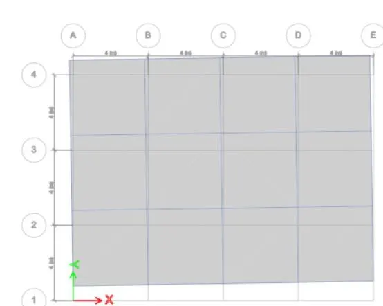
- The grids spacing at 4m in X direction(4 bays) and 4m in Y direction(3 bays).
- To add the material properties of concrete in M30.
- Rebars in HYSD415.
- The beam size is 300mm x 400mm
- The Columns Size is 800mm x 800mm.
- The slab thickness is 150mm thick.
- This structure is framed by 25 story building and each story height is 3m.
- To add the loads and set the load patterns of dead, live and earthquake(seismic) load.
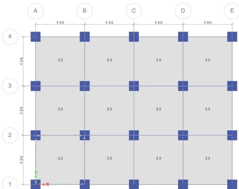
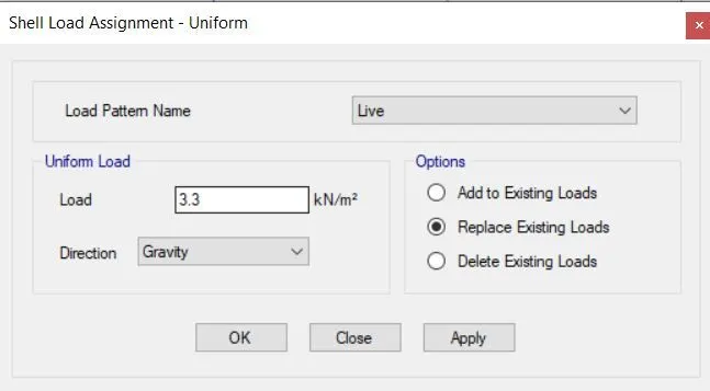
- The Imposed mass of this building is 10% larger than 3 KN/m^2. (i.e) = 3.3KN/m^2.
- The brickwall infill is 10KN/m.
- Then, to Assign the mass properties, Load combinations, diaphragms, modal analysis.
- After that, to check the model and RUN the analysis.
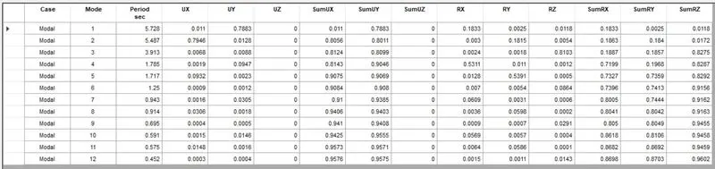
- Next to get the data of TIME PERIOD and MODE SHAPES at 12 stages.
- For choosing, DISPLAY > show tables.
Structure – K:
- Open the new model.
- Set the units at Indian parameters.
- Next to prepare the story and Grids formation.
- The grids spacing at 4m in X direction(4 bays) and 4m in Y direction(3 bays).
- To add the material properties of concrete in M30.
- Rebars in HYSD415.
- The beam size is 300mm x 400mm
- The Columns Size is 800mm x 800mm.
- The slab thickness is 150mm thick.
- This structure is framed by 25 story building and each story height is 3m.
- To add the loads and set the load patterns of dead, live and earthquake(seismic) load.
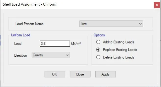
- The Imposed mass of this building is 20% larger than 3 KN/m^2. (i.e) = 3.6KN/m^2.
- The brickwall infill is 10KN/m.
- Then, to Assign the mass properties, Load combinations, diaphragms, modal analysis.
- After that, to check the model and RUN the analysis.
- Next to get the data of TIME PERIOD and MODE SHAPES at 12 stages.
- For choosing, DISPLAY > show tables.
Comparison 1
Effect of stiffness on T: compare fundamental natural periods of building E & F as well as G & H . why is there a marginal or significant difference in the fundamental natural periods.
- The natural period of E is 2.91s
- The natural period of F is 2.66s
- The natural period of G is 3.86s
- The natural period of H is 3.906s
- Comparing a building of E,F,G & H are having a different natural period of occur due to depending upon lateral forces action.
- Because of the building E & F are 10 story with a different size of column fixation and more vary the story column size.
- The same for building G & H are 25 story with a different column sizes with different stories.
- Therefore , the structure having gradually increases the load, so the stiffness of this building becomes changing.
- Since, here considering for variation of reduced the moment of inertia, the overall stiffness of the structure will reduce.
- Due to reduced stiffness about structure similarly the structure could relatively flexible and hence would attracting the lower seismic forces.
Comparison 2
Effect of mass on T : compare fundamental natural periods of building H, J & K. Have the building becomes more flexible or stiff due to change in mass
- The natural period of H is 5.48s
- The natural period of J is 5.47s
- The natural period of K is 5.499s
- The fundamental natural period of building is slightly varying, because of addition of imposed load 10% more than H in J Building and 20% more than H in K Building.
- But , this factor varying is minor to comparing other compoents.
- The mass of structure have increased, it extend to extra deformation in response to an lateral forces, so structure have more flexible an object , obviously the stiffness is less in it.
Comparison 3
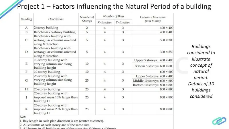
Effect of building height on T: How does the fundamental natural periods of buildigs A,B,F and H change with change in building.
- The natural period of A is 0.60s
- The natural period of B is 1.25s
- The natural period of F is 2.66s
- The natural period of H is 3.90s
- The building of A is 2 story, B is 5 story, F is 10 story and H is 25 story.
- The building height is varying , same varying the cross-wing forces.
- Therefore, the high rise building will affect the thermal expansion and wind forces across the srcture, so the structure need more efficient framed model to prevent from win load action.
Comparison 4
Effect of column orientation on T: How does the fundamental natural periods of buildigs B,C & D change with change in column orientation.
- The natural period of B is 1.25s
- The natural period of C is 1.34s
- The natural period of D is 1.30s
- For this comparision , the story height are same ( 5 stories), but the column orientation get varied from one another like B is 400mm x 400mm for same orientation in both direction, C is 550mm x 300mm for orientation along X direction and D is 300mm x 550mm along Y direction.
- Therefore, the framed section
- are varying from one another, may it have occur some variation of natural period during the seismic loads action.
Comparison 5
Effects of flexural stiffness of structural elements on Mode shapes: compare fundamental natural periods of building B in two situation when flexural stiffness of beams relative to that of adjoining columns is very small versus when it is large.
- The natural period of B in T1 is 1.25s ( MODE 1 )
- The natural period of B in T2 is 1.087s ( MODE 2 )
- The column rigidity is more higher with fixed supports. The higher is more effectiveness for flexural stiffness.
Comparison 6
Effects of Axial stiffness of vertical members on mode shapes: compare fundamental natural periods of building H in two situation when Axial cross-sectional area of columns is very small Versus When it is Large.
- The natural period of H in T1 is 5.71s ( MODE 1 )
- The natural period of H in T2 is 5.41s ( MODE 2 )
- To compare the mode shape of natural period of higher is better axial stiffness to resist of witstanding of structure to formation of deflection at members.
Comparision 7
Effect of degree of fixity at column base on mode shape : compare fundamental natural periods of building B in two situation when base of column is pinned versus when it is fixed.
- The natural period of B in T1 is 1.25s ( MODE 1 )
- The natural period of B in T2 is 1.087s ( MODE 2 )
- The rotational stiffness at the base of a column affects the force and displacements demands on frame elements during an earthquake.
- In most analysis conducted for design, the column base is considered to be fully fixed.
- They showed that pinned to fully fixed column base cases bounded the responses for all frames.