Project - Speed Control of a Direct Current (DC) motor
Aim:
Project - Speed Control of a Direct Current (DC) motor
Objective:
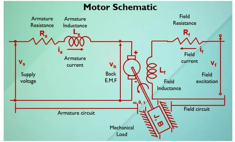
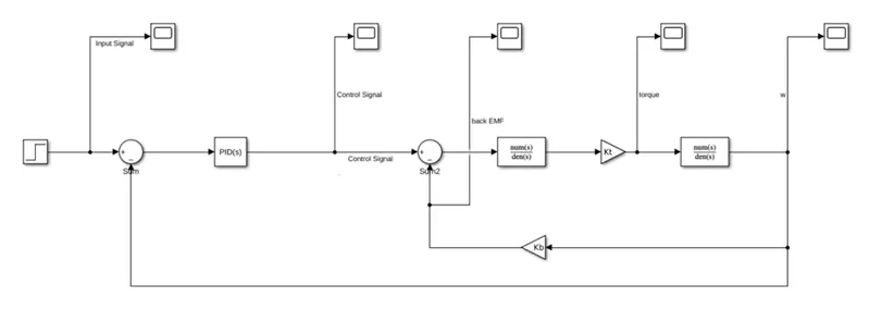
In this project, a Simulink model for the DC motor will be first developed per the schematic shown in Figure 1.
Use the Proportional, Integral, and Derivative (PID) control design knowledge gained in the training to design, develop and test a controller to maintain a desired speed for the motor.
Solutions:
MATLAB Code:
%% DC Motor parameters
J=0.01; %Intertia of motor
B=0.1; %Motor viscus friction
Kb=0.01; %Back EMF
Kt=0.01; %Motor torque constant
Ra=1.0; %Armature resistancde
La=0.5; %Inductance of the motor
%% PID Design
A=[-B/J Kt/J; -Kb/La -Ra/La];
D=[0 ; 1/La];
%% Poles of systema
Fn=1;
Wn=2*pi*Fn;
zeta=0.5;
p1=-zeta*Wn+Wn*sqrt(zeta^2-1);
p2=-zeta*Wn-Wn*sqrt(zeta^2-1);
p=[p1;p2];
P=place(A,D,P);
%PID constants
Ki=0;
Kp=38.3133;
Kd=-2.8584;
%% Placing poles and zeros system
K=1; %The DC gain of the system
s=tf('s');
G=K*Wn^2/(s^2 + 2*zeta*Wn^2 + Wn^2);
pzmap(G,'r'); grid on;
Here with poles placement, we can find Kp and Kd gains for controller of the system
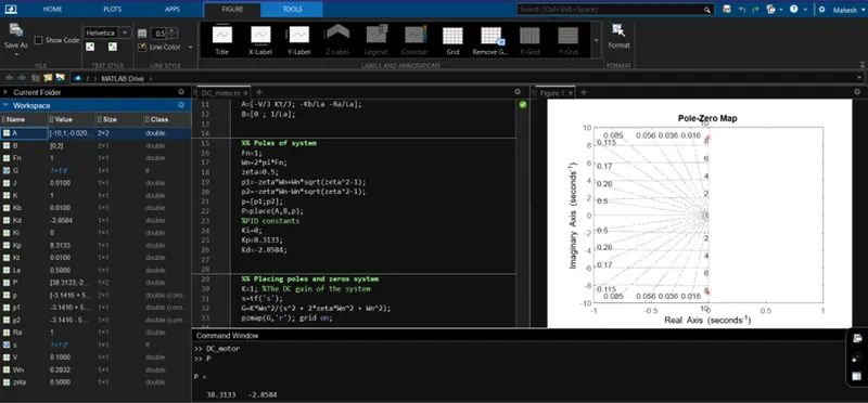
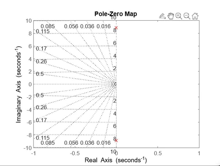
Pole of the system lies on the axis of the graph, hence we can conclude that the system is critically stable . . . . .
SIMULINK Model:
- Designing a PID controller:
- MATLAB code:
%% Poles of systema
Fn=1;
Wn=2*pi*Fn;
zeta=0.5;
p1=-zeta*Wn+Wn*sqrt(zeta^2-1);
p2=-zeta*Wn-Wn*sqrt(zeta^2-1);
p=[p1;p2];
P=place(A,D,P);
%PID constants
Ki=0;
Kp=38.3133;
Kd=-2.8584;
- According to the values that we have got in above equations for Kp & Kd gains
- Take three gain constants Kp, Ki & Kd.
Where, as Kp is Proportional gain
Ki is Integral Gain
Kd is Differential Gain
- For Integral gain add an Integrator block ahead of Ki from SIMULINK model.
For Differential gain either keep a feedback or use a differential block from SIMULINK model ahead of Kd gain block.
- Connect the blocks accordingly forming a PID controller
- Designing a DC motor:
MATLAB script:
%% DC Motor parameters
J=0.01; %Intertia of motor
B=0.1; %Motor viscus friction
Kb=0.01; %Back EMF
Kt=0.01; %Motor torque constant
Ra=1.0; %Armature resistancde
La=0.5; %Inductance of the motor
- Write a MATLAB script as shown above
- Take a transfer function block of 1 wrt La Ra refer fig (A)
- Take a transfer function block of 1 wrt J B refer fig (B)
- Take two gain blocks Kt & Kb.
- Where as Kt is motor torque & Kb is back emf which us here for negative feedback
- Connect the parameters accordingly
- Along the second transfer function we get W
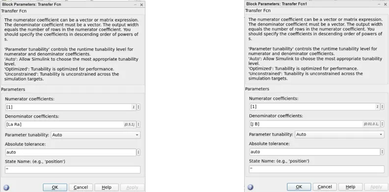
Fig (A) Fig (B)
SIMULINK Model:
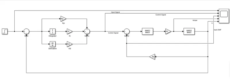
Connect the parameters accordingly,
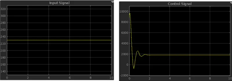
Input signal Control Signal
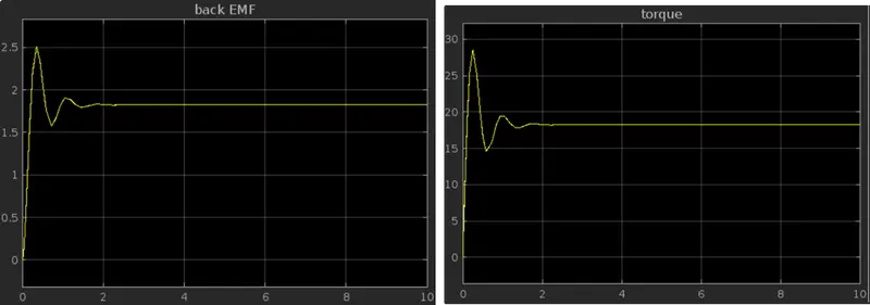
Back EMF Torque
W:
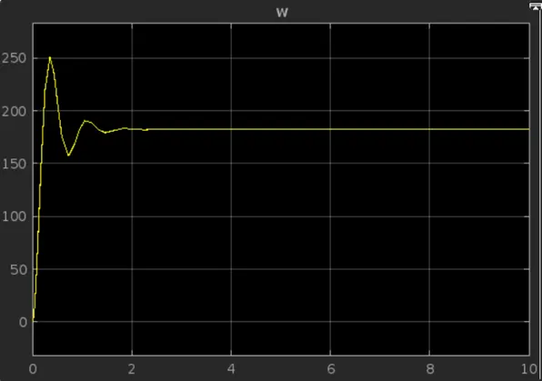
Rise time: 0.1 to 0.3
Peak: 250
Peak time: 0.3
Settling max:250
Settling min:165
Settling time: 1.0 to 1.8
SIMULINK Model:
For the below mode we are using a discrete PID controller a MATLAB block
As the same results can be obtained by using a PID controller block
Reference:
DC model link:
https://skill-lync.com/knowledgebase/modeling-of-dc-motor
PID controller design for DC motor:
https://skill-lync.com/knowledgebase/pid-controller-design-for-dc-motor
MATLAB script:
https://drive.google.com/file/d/1KLRI80rYyLGg5pOW9fRRUhmOtETH9Kt4/view?usp=share_link
SIMULINK model:
https://drive.google.com/file/d/14IedyxL-y_pPuZVPe8YWSzl-ytPjI6as/view?usp=share_link
_____________________________________________________________________________________________________________________