Week-7 Challenge: DC Motor Control
Aim:
DC Motor Control
Objective:
- A. Explain a MATLAB demo model named ‘Speed control of a DC motor using BJT H-bridge’.
- Comment on the armature current shoot-up from the scope results.
- Refer to the help section of ‘The Four-Quadrant Chopper DC Drive (DC7) block’. Compare it with the H-bridge model.
- Develop a 2-quadrant chopper using Simulink & explain the working of the same with the relevant results. (Refer to article – Multiquadrant operation of motor)
- Explain in a brief about operation of BLDC motor.
Objective 1:
- A. Explain a MATLAB demo model named ‘Speed control of a DC motor using BJT H-bridge’.
- B. Comment on the armature current shoot-up from the scope results.
- C. Refer to the help section of ‘The Four-Quadrant Chopper DC Drive (DC7) block’. Compare it with the H-bridge model.
Theory:
Open the ‘Speed control of a DC motor using BJT H-bridge’
- The Bipolar Junction Transistor (BJT) when used for power switching applications, operates as an IGBT.
- When it is conducting (BJT operating in the saturated region), a forward voltage Vf is developed between collector(C) and emitter(E) (range of 1 V).
- Therefore, the IGBT block can be used to model the BJT device.
Model Description: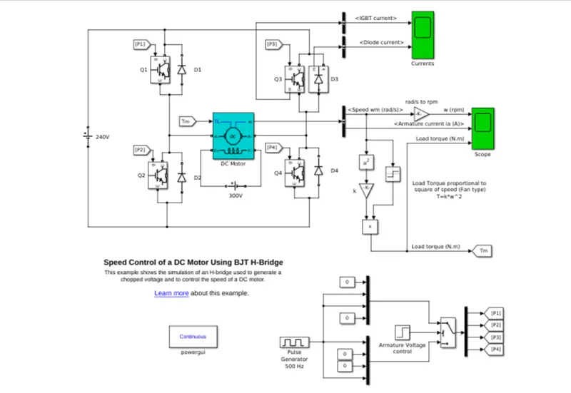
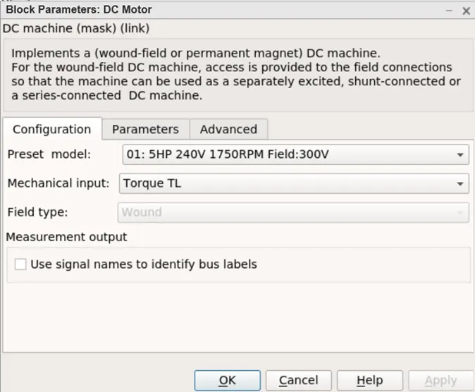
- Given DC motor specifications 5HP 240V 1750RPM. The armature mean voltage can be varied from 0 to 240 V when the duty cycle (specified in the Pulse Generator block) is varied from 0 to 100%.
- The H-bridge consists of four BJT/Diode pairs (BJT simulated by IGBT models)
- Two transistors are switched simultaneously: Q1 and Q4 or Q2 and Q3.
- When Q1 and Q4 are fired, a positive voltage is applied to the motor and diodes D2-D3 operate as free-wheeling diodes when Q1 and Q4 are switched off.
- When Q2 and Q3 are fired, a negative voltage is applied to the motor and diodes D1-D4 operate as free-wheeling diodes when Q2 and Q3 are switched off.
Simulation Result:
Zooming in
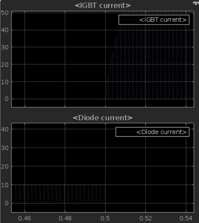
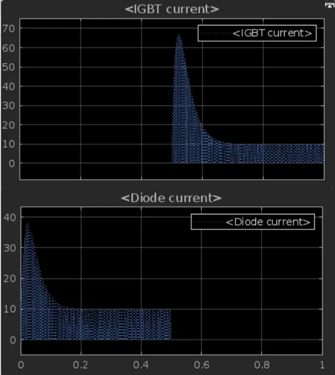
Thus, from above graph we can see that, for 0 to 0.5 sec, the current flows through diode D3 and from 0.5 sec to 1 sec, the current flows through Q3.
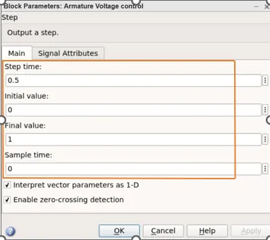
The motor starts in the positive direction with a duty cycle of 75%, i.e., DC voltage of 180V.
At t= 0.5 sec., the armature voltage is suddenly reversed and the motor runs in the negative direction.
Theory: 1. B
The waveform for speed, armature current and load torque is shown in below graphs.
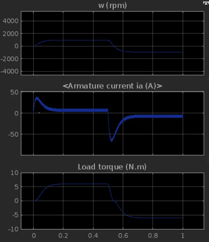
From armature current graph, we can see that, at starting there is sudden spike increase in current at 0 sec also and 0.5 sec also.
We can see that, as the voltage gets changed in the circuit, the speed of motor also changes.
In this transition of positive to negative direction of rotation we observe a high surge in current, this is due to the transient switching occurring in the circuit.
As there is already current flowing in the circuit & on changing of switches after 0.5 sec, the current in the circuit adds to the changed direction of current and we observe a surge.
After reducing the duty cycle to 50% the changes can be seen in the Armature current.
A small spik can be seen at the 0.5 sec
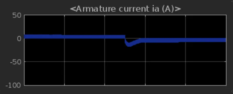
Thus, we can find that, the armature current spike is reduced by changing the duty cycle from 75% to 50%.
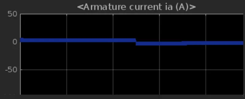
Again, duty cycle is reduced to 35%
Result:
As we continue decreasing the duty cycle the spike in the armature current reduces
Theory: 1. C.
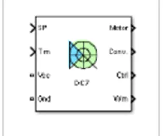
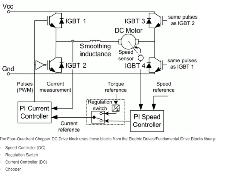
The Four-Quadrant Chopper DC Drive (DC7) block represents a four-quadrant, DC-supplied , chopper (or DC-DC PWM converter) drive for DC motors. This drive features closed-loop speed control with four-quadrant operation. The speed control loop outputs the reference armature current of the machine. Using a PI current controller, the chopper duty cycle corresponding to the commanded armature current is derived. This duty cycle is then compared with a sawtooth carrier signal to obtain the required PWM signals for the chopper.
The main advantage of this drive, compared with other DC drives, is that it can operate in all four quadrants (forward motoring, reverse regeneration, reverse motoring, and forward regeneration). In addition, due to the use of high switching frequency DC-DC converters, a lower armature current ripple (compared with thyristor-based DC drives) is obtained. However, four switching devices are required, which increases the complexity of the drive system.
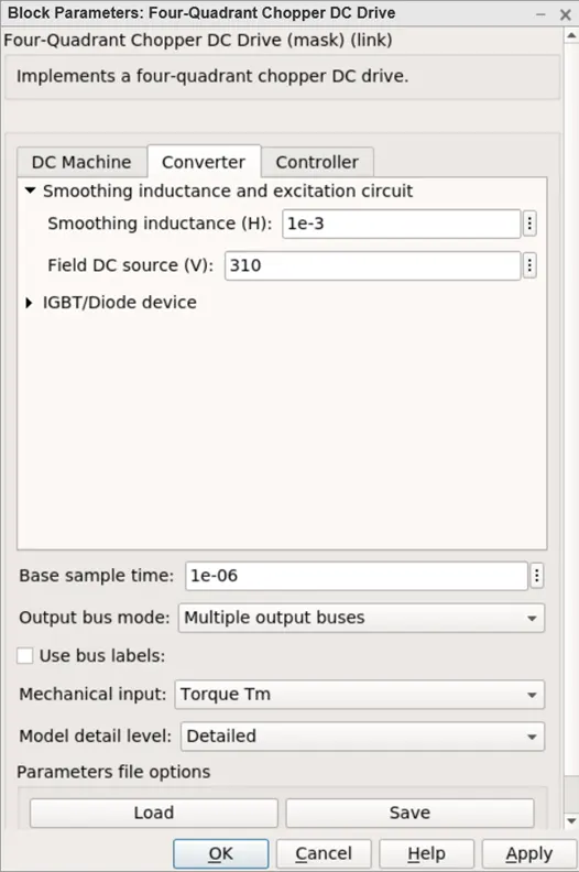
Block parameters:

Connection:
Inputs and outputs:
Armature voltage, speed reference, motor torque reference is given as inputs.
Motor, convertor, controller, motor angular speed get as outputs.
Working:
- Here Four Igbt switches are used.
- Here pulses are given from PI current controller, that controls the pulses by comparing armature current measurement and current reference.
- Current reference can be generated by using regulation switch in that torque reference and PI speed controller pulses, that internally compared by speed of motor and reference speed given as input.
- Mainly speed controlled by current controller.
- In this case Four quadrant operations are performed.
- Forward motoring mode, forward regenerative breaking mode: Q1, Q4 are on and Q2, Q3 are in off.
- Reverse motoring mode, reverse regenerative breaking mode: Q2, Q3 are on and Q1, Q4 are in off.
Comparisons:
- In DC7 chopper model speed controlled by varying current pulses from PI current controller and in H-bridge model speed controlled by varying duty cycles voltages.
- Here regenerative breaking in occurring while in H-bridge model breaking is occurred by changing polarity of current flow dynamic breaking occurs in it.
- In four quadrant DC chopper model smoothing inductance is used for smooth increase and decrease in current flow which in turns controlling the motor speed smoothly, while in
- H-bridge it is not present.
- Here the operation is discrete and in H-bridge model it is continuous.
- Hence 4 quadrant DC choppers are used mostly in electric vehicles.
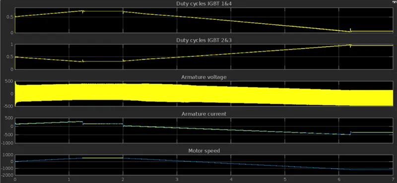
Scope Results:
Objective 2:
Develop a 2-quadrant chopper using Simulink & explain the working of the same with the relevant results. (Refer to article – Multiquadrant operation of motor)
Theory:
Two Quadrant Chopper
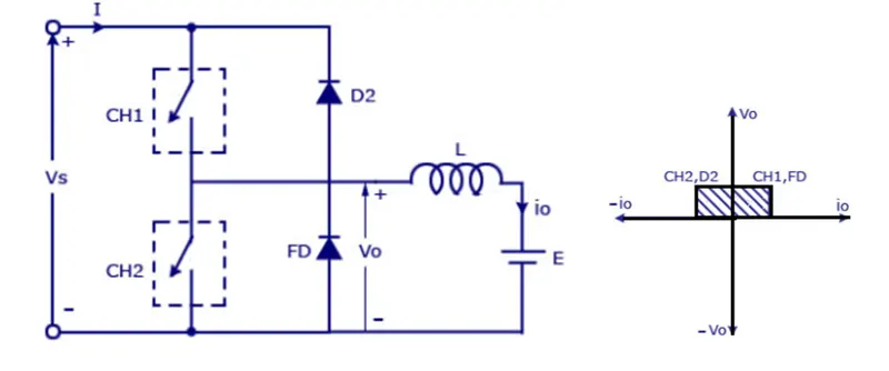
In this type of Chopper, the average voltage will be always positive but the average load current might be positive or negative. The two Switches CH1 and CH2 should not be turned on simultaneously as the combined action may cause a short circuit in supply lines. For regenerative braking and motoring this type of chopper configuration is used.
We will always get a positive output voltage V0 as the freewheeling diode FD is present across the load. When the chopper CH1 is on the current flows from source to load. The inductor stores energy. When Ch1 turn OFF the freewheeling diode starts conducting and the output voltage v0 will be equal to Vs. The direction of the load current i0 will be reversed. The current i0 will be flowing towards the source. The load current will be negative when the CH2 is on. The current completes its path through diode D2.
Model Parameters:
Vs=DC voltage source.
CH1= Power electronic switch 1.
CH2= Power electronic switch 2.
D2, FD= Free wheeling diodes.
L=Inductor load.
Refer to the diagram for connections,
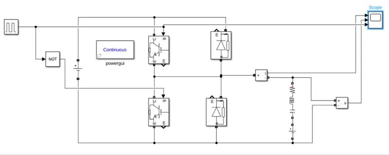
MATLAB Model:
Model Operation:
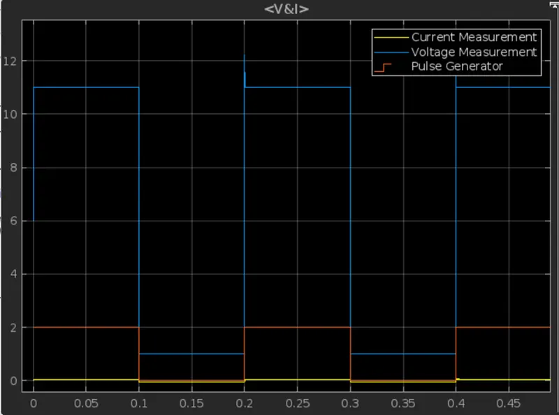
- Here either one should be ON at a time, either CH1 or CH2.
- If CH1 is ON the current flows from source +ve to load(here DC motor),passes through L and E to -ve terminal of source.(1st quadrant)
- If CH1 is OFF the, FD diode conducts and complete the circuit (L-E-FD-L) as stored energy in inductor L. The voltage across is also positive voltage, current direction also positive.
- Now If CH2 is ON, Current flow from E(Load current) completes the circuit(L-CH2-E).
- If CH2 gets OFF, the current passes through D2 towards source completes the circuit(E-L-D2-+ve source- -ve source-E).
- In this stage regenerative breaking occurs. (2nd quadrant).
- This cycle continuous again upto stop time.
Result:
Objective 3:
Explain in a brief about operation of BLDC motor.
Theory:
Brushless DC Motors or BLDC Motors have become a significant contributor of the modern drive technology. Their rapid gain in popularity has seen an increasing range of applications in the fields of Consumer Appliances, Automotive Industry, Industrial Automation, Chemical and Medical, Aerospace and Instrumentation.
A BLDC motor is a type that is most suitable for applications that require high reliability, high efficiency, more torque per weight, etc.
A Brushless DC Motor is similar to a Brushed DC Motor but as the name suggests, a BLDC doesn’t use brushes for commutation but rather they are electronically commutated. In conventional Brushed DC Motors, the brushes are used to transmit the power to the rotor as they turn in a fixed magnetic field.
Working Principle:
Whenever a current carrying conductor placed in a magnetic field it experiences a force. As a consequence of reaction force, the magnet will experience an equal and opposite force. (Lorentz force law)
Working:
Before explaining the working of a brushless DC motor, it is better to understand the function of a brushed motor. In brushes motors, there are permanent magnets on the outside and a spinning armature which contains electromagnet is inside. These electromagnets create magnetic field in the armature when the power is switched on and help to rotate the armature.
The brushes change the polarity of the pole to keep the rotation on of the armature. The basic working principle for the brushed DC motor and for brushless DC motor are same i.e., internal shaft position feedback.
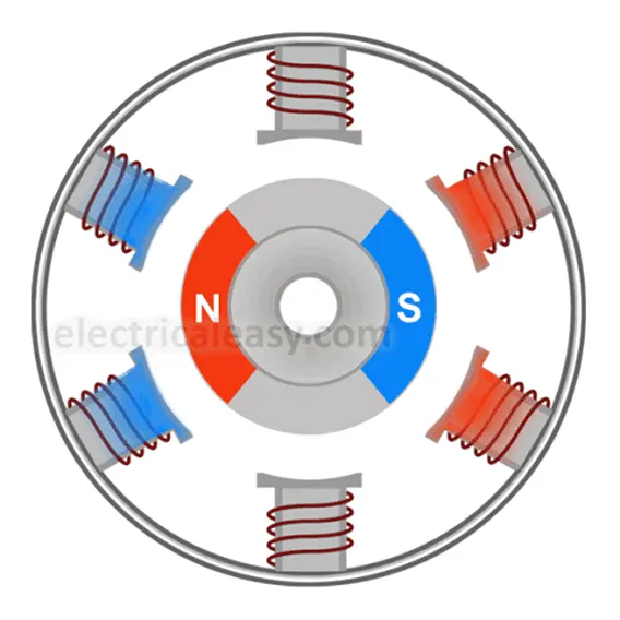
Brushless DC motor has only two basic parts: rotor and the stator. The rotor is the rotating part and has rotor magnets whereas stator is the stationary part and contains stator windings. In BLDC permanent magnets are attached in the rotor and move the electromagnets to the stator. The high-power transistors are used to activate electromagnets for the shaft turns. The controller performs power distribution by using a solid-state circuit.
Types of BLDC Motor:
Basically, BLDC are of two types, one is outer rotor motor and other is inner rotor motor. The basic difference between the two is only in designing, their working principles are same.
- Inner Rotor Motor: In an inner rotor design, the rotor is located in the centre of the motor and the stator winding surround the rotor. As the rotor is located in the core, rotor magnets do not insulate heat inside and heat get dissipated easily. Due to this reason, inner rotor designed motor produces a large amount of torque and validly used.
Outer Rotor Motor: In outer rotor design, the rotor surrounds the winding which is located in the core of the motor. The magnets in the rotor trap the heat of the motor inside and do not allow to dissipate from the motor. Such type of designed motor operates at lower rated current and has low cogging torque.
- Advantages of BLDC Motor:
- It has no mechanical commutator and associated problems
- High efficiency due to the use of permanent magnet rotor
- High speed of operation even in loaded and unloaded conditions due to the absence of brushes that limits the speed
- Smaller motor geometry and lighter in weight than both brushed type DC and induction AC motors
- Long life as no inspection and maintenance is required for commutator system
- Higher dynamic response due to low inertia and carrying windings in the stator
- Less electromagnetic interference
- Quite operation (or low noise) due to absence of brushes
Disadvantages of BLDC Motor:
- These motors are costly
- Electronic controller required control this motor is expensive
- Not much availability of many integrated electronic control solutions, especially for tiny BLDC motors
- Requires complex drive circuitry
- Need of additional sensors
- Operates only on DC power
For more referencde refer to the file attahded below