Week-6 Challenge: EV Drivetrain
Aim: EV Drivetrain Analysis
Objectives:
- Which types of power converter circuits are employed in electric and hybrid electric vehicle?
- An Electric Vehicle's powertrain with 72V battery pack in shown in the diagram below. The duty ratio for acceleration operation is 'd1' and for the braking operation the duty ratio is 'd2'.
The other parameters of the electric vehicle are given below,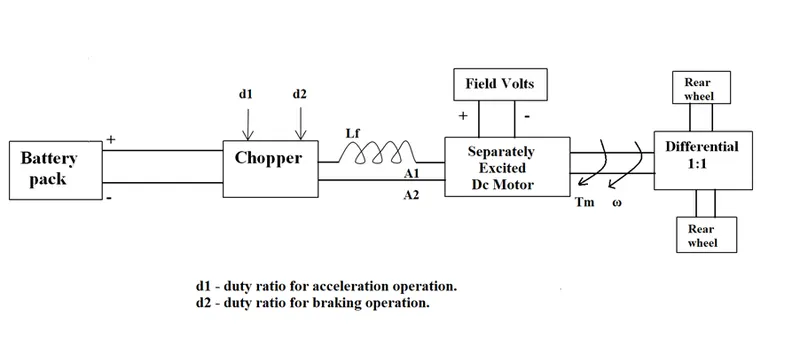
Motor and Controller Parameters:
Rated Armature voltage= 72 V
Rated armature current= 400 A
Ra= 0.5Ω, KΦ= 0.7 Volt second
Chopper Switching frequency= 400 Hz
The vehicle speed-torque characteristics are given by the below equation

What is EV steady state speed if duty cycle is 70%?
- Develop a mathematical model of a DC Motor for the below equation using Simulink.
ωω= V/Kϕϕ -Ra/Kϕϕ^2.T
- Refer to the blog on below topic:
Induction Versus BLDC motors by Wally Rippel, Tesla
Explain in brief about author’s perspective.
Objective 1:
Which types of power converter circuits are employed in electric and hybrid electric vehicle?
Theory:
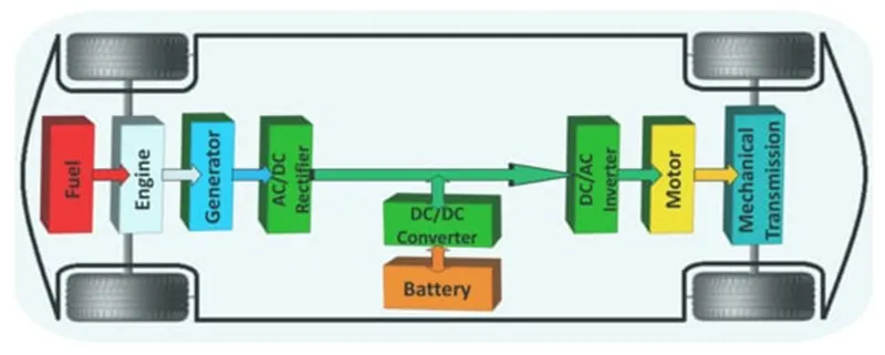
In Electric and Hybrid Electric Vehicles (EV/HEV), the power converters are considered as the key elements that interface their power sources to the drivetrain.
Depending on the type & function of the power converters they classified into following
- AC to DC power converter (Rectifier)
- DC to DC power converter (Chopper)
- DC to AC power converter (Converter)
AC to DC power converter (Rectifier):
In AC to DC converters are most commonly used in Plug-in Electric Vehicles (PEV) & Plug-in Hybrid Electric Vehicles (PHEV) These vehicles get their propulsion power from an external source i.e. charging stations which is alternating current (AC). As the battery needs to be charged using a direct current source (DC). For this purpose, AC to DC converter is employed in a PHEV & PEV.
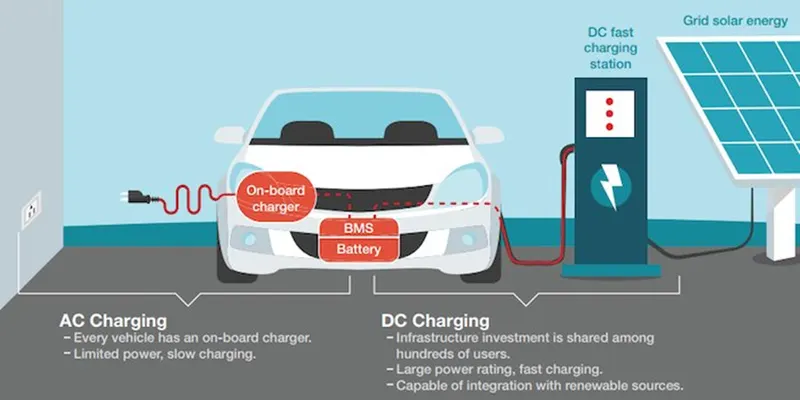
DC to DC power converter (Chopper):
DC-DC converters can be used to interface the elements in the electric powertrain by boosting or chopping the voltage levels. By introducing DC/DC converters one can choose the voltage variation of the devices and the power of each device can be controlled. The power of the DC/DC converter depends on the characteristics of the vehicle such as top speed, acceleration time from 0 to 100 Km/h, weight, maximum torque, and power profile (peak power, continuous power).
DC to AC power converter (Inverter):
An inverter serves the same kind of function in a hybrid or EV car. The DC to AC converter is required to convert the DC power to a suitable AC power for the electrical machine. The power output from battery pack (DC current) is converted using inverter to be used in electric motor (AC current).
Objective 2:
An Electric Vehicle's powertrain with 72V battery pack in shown in the diagram below. The duty ratio for acceleration operation is 'd1' and for the braking operation the duty ratio is 'd2'.
Motor and Controller Parameters:
Rated Armature voltage= 72 V
Rated armature current= 400 A
Ra= 0.5Ω, KΦ= 0.7 Volt second
Chopper Switching frequency= 400 Hz
The vehicle speed-torque characteristics are given by the below equation
 …..equation(i)
Theory:
Duty cycle=70%=0.7,
Actual voltage=0.7*72=50.4V
We have torque equation for motor,
T = (V×Kø/Ra)-(V×Kø2/Ra)w
T = (50.4×0.7/0.5)-[50.4× (0.7)2×0.5]
T=70.56−0.98⋅ωT = 70.56-0.98⋅ω .....equation(ii)
Comparing both torque of vehicle and torque of motor,
24.7+(0.0051)⋅ω2=70.56−(0.98)⋅ω24.7+(0.0051)⋅ω2=70.56-(0.98)⋅ω
0.0051ω2+0.98ω−45.86=0
By solving this by quadratic equation we get,
We get two ω values as
ω = 38.915rad/sec and ω = −231.072rad/sec
So, the EV steady state speed if duty cycle is 70% = 38.915 rad/sec or 371 RPM
Objective 3:
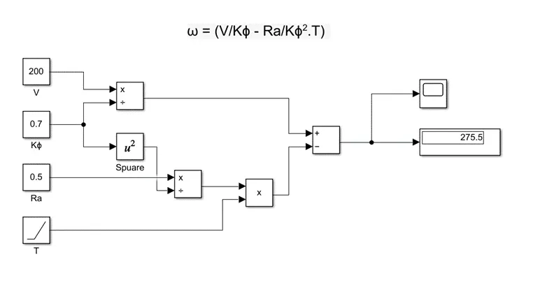
Develop a mathematical model of a DC Motor for the below equation using Simulink.
ω= (V/Kϕ -Ra/Kϕ2.T)
Theory:
The given equation is ω= (V/Kϕ -Ra/Kϕ2.T)
Steps:
- Take four constants
- Name them as V, Kø, Ra & T accordingly
- Divide V by Kø .... Equation (A)
- Use math function block to make square of Kø
- Divide Ra by Kø
- Take Ramp for T, multiplied by above term
- Now use as per sign convention .... Equation (B)
Now as per the equation Subtract the Equation (B) from Equation (A)
SIMULINK Model:
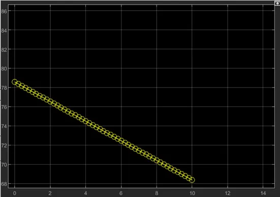
Scope Output:
Objective 4:
Refer to the blog on below topic:
Induction Versus BLDC motors by Wally Rippel, Tesla
Explain in brief about author’s perspective
Theory:
Induction versus BLDC motor
According to authors perspective, firstly he gave the description of BLDC motor about its parts and specifications and what is called and next description about Induction motor about is component and working of Induction motor. Then he compared the BLDC and induction which he mentioned that 3- phase induction motor can produce output torque and also have an ability to start under the load without any inverter, as of BLDC motor produces no starting torque when directly connected to fixed frequency utility power and also inverter is needed to start under load. Then he discussed about the limitations of the 3-Phase induction motor they cannot operate from DC; AC is a must. Shaft speed is proportionate to line frequency. Hence, when used with utility power, they are constant speed machines. Finally, when operated from utility power, they have limited starting torque and somewhat limited running peak torque capabilities, when compared to DC type machines. Inverter can be added to 3-Phase induction so that we can supply power from DC source or Battery and also we can get variable speeds and can adjust the frequencies.
Then he discussed as the only main difference between BLDC and Induction motor is of control code and also the rotor of BLDC gets less heated at peak torque as that of Induction motor rotor.
Then he discussed about the loses when the motor runs which is the induction machine when operated with a smart inverter has an advantage over a BLDC machine – magnetic and conduction losses can be traded such that efficiency is optimized. This advantage becomes increasingly important as performance is increased. With BLDC, as machine size grows, the magnetic losses increase proportionately and part load efficiency drops. With induction, as machine size grows, losses do not necessarily grow. Thus, induction drives may be the favoured approach where high-performance is desired; peak efficiency will be a little less than with BLDC, but average efficiency may actually be better.
He concluded with that BLDC drives will likely continue to dominate in the hybrid and coming plug-in hybrid markets, and that induction drives will likely maintain dominance for the high-performance pure electrics.
Result:
- Studied power converters in EV’s & HEV’s
- Solved the equations and found steady state speed of Vehicle
- Prepared a Simulink model for given equation with speed scope output
- Compared the BLDC with Induction motor