Project - Speed Control of a Direct Current (DC) motor
SPEED CONTROL OF DIRECT CURRENT (DC) MOTOR
OBJECTIVE:
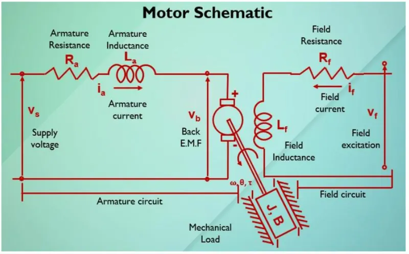
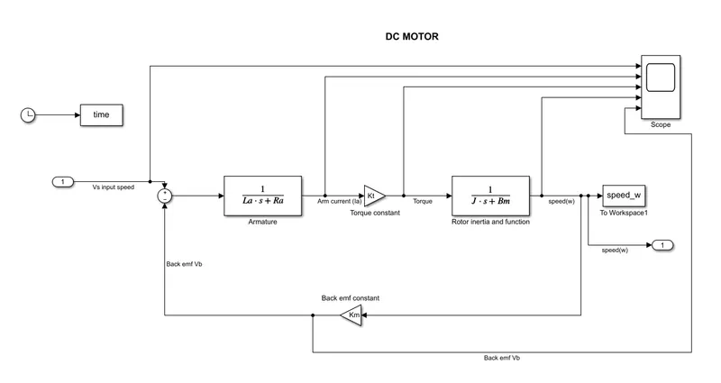
In this project, a Simulink model for the DC motor will be first developed per the schematic shown in Figure 1.
Use the Proportional, Integral, and Derivative (PID) control design knowledge gained in the training to design, develop and test a controller to maintain a desired speed for the motor.
INTRODUCTION:
A DC motor is an electrical machine that converts electrical energy into mechanical energy. In a DC motor, the input electrical energy is the direct current which is transformed into the mechanical rotation.
PID controller:
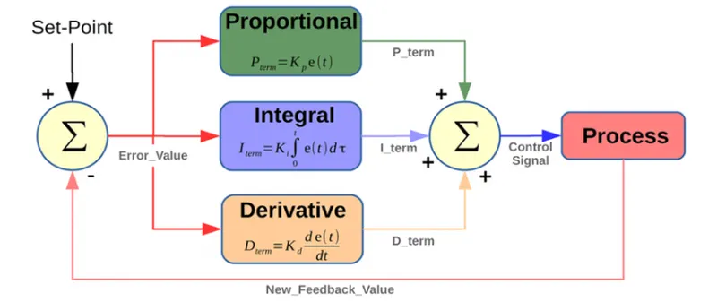
The Proportional-Integral-Derivative (PID) controller. The PID controller is widely employed because it is very understandable and because it is quite effective. One attraction of the PID controller is that all engineers understand conceptually differentiation and integration, so they can implement the control system even without a deep understanding of control theory. Further, even though the compensator is simple, it is quite sophisticated in that it captures the history of the system (through integration) and anticipates the future behavior of the system (through differentiation).
A PID controller is actually a three part system:
- Proportional compensation: the main function of the proportional compensator is to introduce a gain that is proportional to the error reading which is produced by comparing the system's output and input.
- Derivative compensation: in a unitary feedback system, the derivative compensator will introduce the derivative of the error signal multiplied by a gain KD. In other words, the slope of the error signal's waveform is what will introduced to the output. Its main purpose is that of improving the transient response of the overall closed-loop system.
- Integral compensation: in a unitary feedback system, the integral compensator will introduce the integral of the error signal multiplied by a gain KI. This means that the area under the error signal's curve will be affecting the output signal.
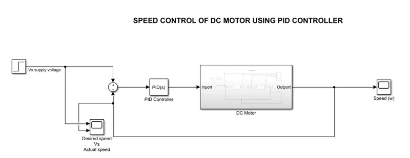
SIMULINK MODEL:

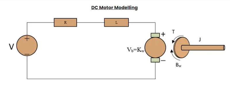
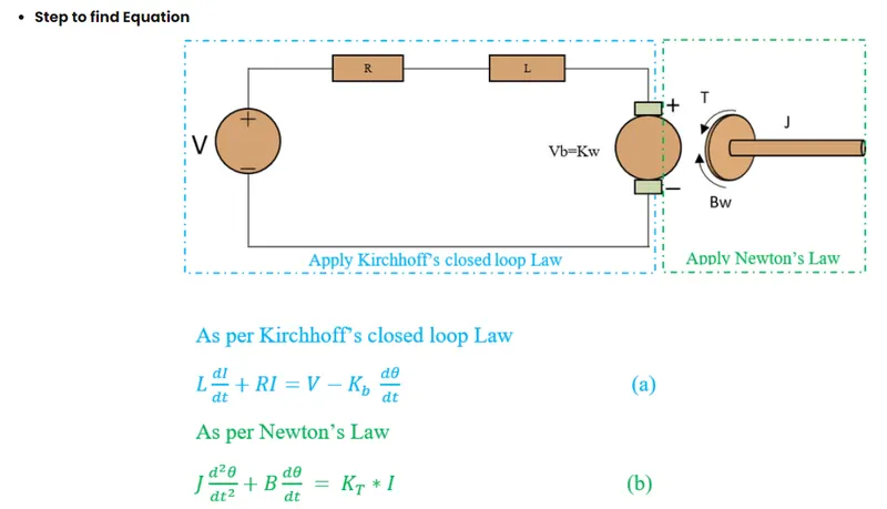
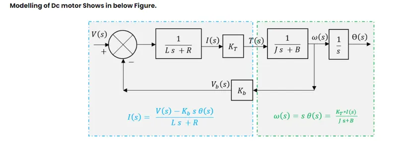
The above transfer function is modeled with pid controller using the simulink primitive blocks.
PID controller block is used here.
Subsystem of DC motor:
MATLAB SCRIPT:
DC motor parameters:
J = 0.01; %moment of inertia of the dc motor kg-m^2
Bm = 0.1; %motor viscous friction constant in N-m-s
Km = 0.01; %back emf constant in V/rad/s
Kt = 0.01; %motor torque constant in N-m/amp
Ra = 1.0; %resistance of armature circuit is ohms
La = 0.5; %Inductance of the armature circuit in henries.
%DC motor parameters
clc;
clear all;
J = 0.01;%moment of inertia of the dc motor kg-m^2
Bm = 0.1; %motor viscous friction constant in N-m-s
Km = 0.01;  %back emf constant in V/rad/s
Kt = 0.01; %motor torque constant in N-m/amp
Ra = 1.0; %resistance of armature circuit is ohms
La = 0.5; %Inductance of the armature circuit in henries.

%PID control design parameters
A = [-Bm/J Kt/J;-Km/La -Ra/La];
B = [0 ; 1/La];
%C = [1 0];
%D = [0];

% [num,den] = ss2tf(A,B,C,D)
% G = tf([0 0 -2],[1 12 19.98]);
% p = pole(G);

%equivalent wn
fn = 1.0; %wn/(2*pi) Hz
wn = 2*pi*fn; %sqrt(k/m) rad/s
zeta = 0.5; %under damped system design
%Desired poles
p1 = -zeta*wn + wn*sqrt(zeta^2-1);
p2 = -zeta*wn - wn*sqrt(zeta^2-1);
p = [p1;p2];

%pole placement
K = place(A,B,p); %control gain k

%kp,ki and kd gains
Kp = K(1);
Kd = K(2);
Ki = 100;
Here, The Kp,Kd,Ki values are calculated using the pole placement method But for our simulation these gains are not required, we get the gains from the PID controller block.
The script is for defining the DC motor parameters.
PID CONTROLLER BLOCK:
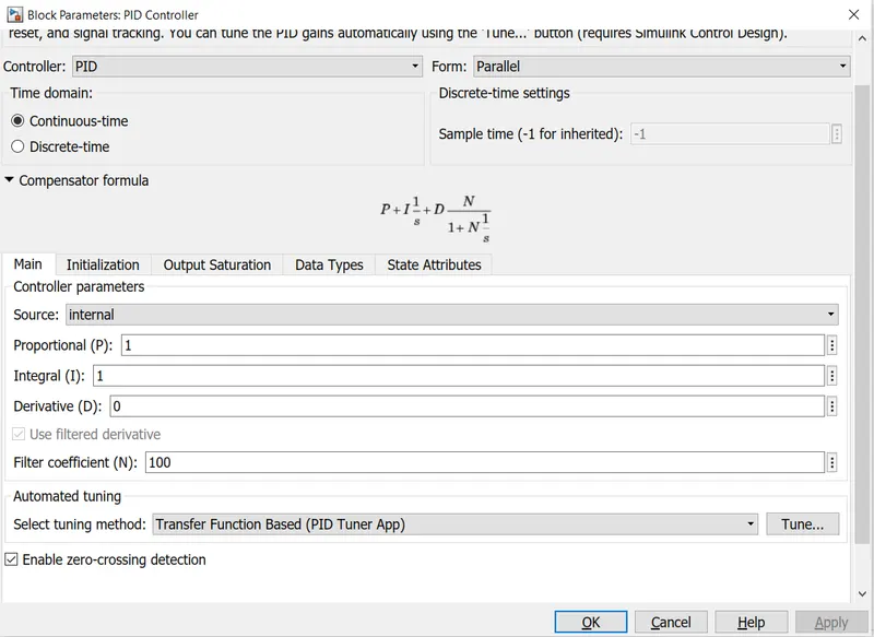
This block implements continuous- and discrete-time PID control algorithms and includes advanced features such as anti-windup, external reset, and signal tracking. You can tune the PID gains automatically using the 'Tune...' button (requires Simulink Control Design).
Continuous time simulation is selected.
DC motor simulation results:
Input:
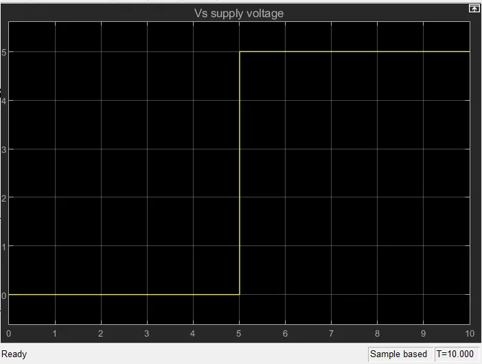
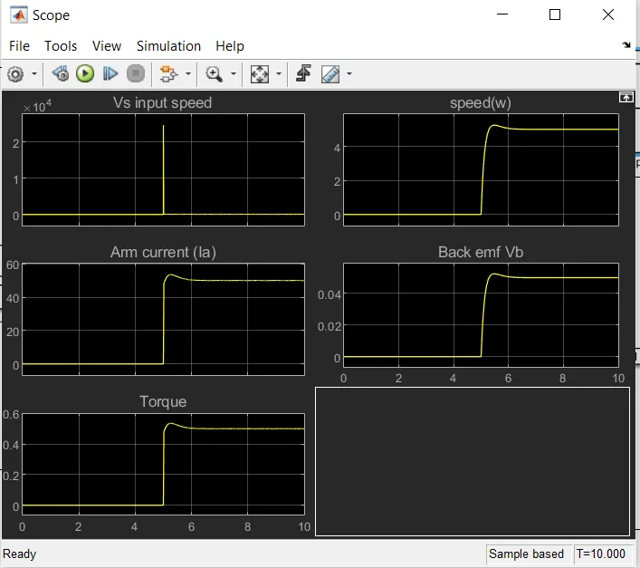
The Input is the supply voltage here,we taken that as reference voltage given that as step input of 5 at 5 secs,
lets consider the input as 5 rad/s the analysis is to check the output response to achive the speed as 5 rad/s.
Simulation Results:
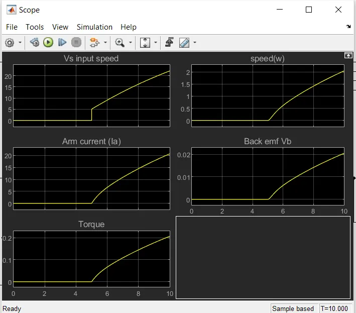
The above plot shows the values of speed,Back emf,Torque,Armature current respect to the reference speed.
ANALYSIS:
The objectives of the control design are
Setting time < 2 secs
Overshoot < 5%
Steady state error < 1%
Here, the Kp,Ki,Kd are selected to obtain the above objectives.
Case 1:
Default P,I,D gains P = 1; I = 1; D = 0
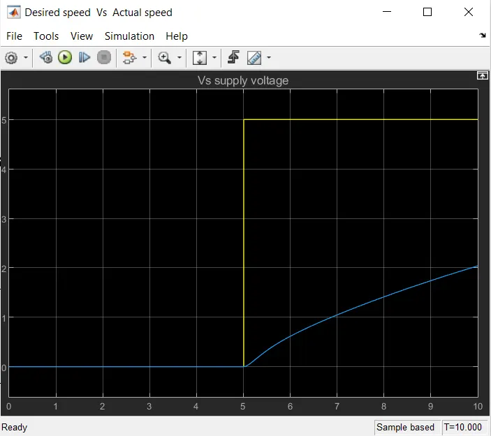
The above simulation shows the tracking is very poor and steady state is not achieved, the desired speed of the dc motor is not achieved and maintained here.
So, the system is need to be tuned for better control of the speed of dc motor.
Case 2:
Tuning using PID controller:

Tuning is done in the PID controller block
The tuned parameters are given below:
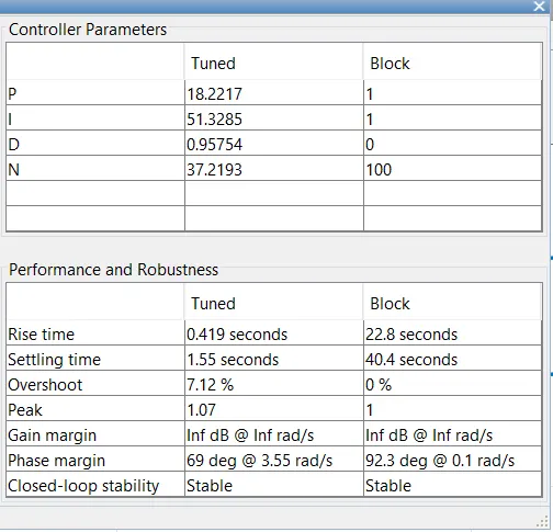
Here, the overshoot is more than 7% rise time and settling time is decreased using the tuned gain values of
P =18.27
I = 51.3
D = 0.95
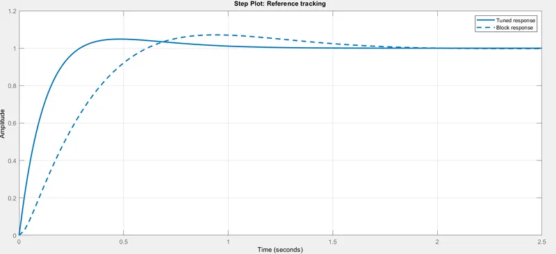
Tune step response is given below,It shows the block response and tuned response
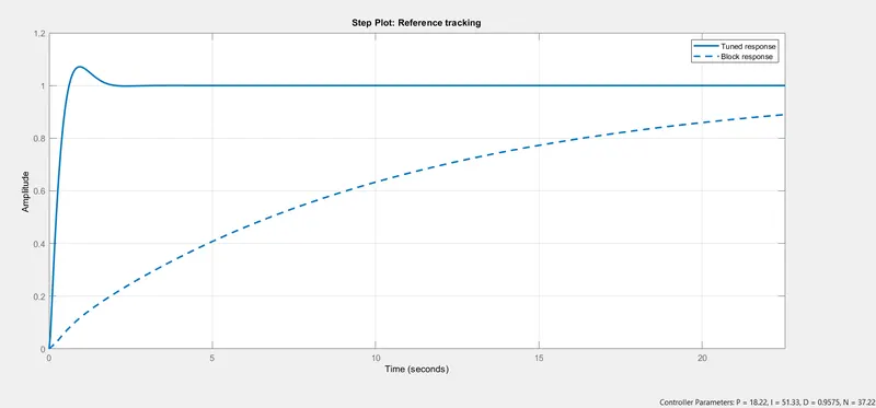
The output result after tuning with updated gain values,the gain values are updated to the block by clicking the update block
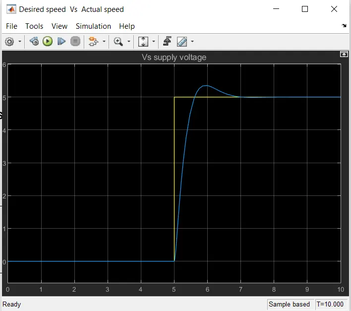
Tune response of the complete system:
The output actual speed is nearly follow the input desired speed using the PID tuner.
The speed of the DC motor is maintained with initial oscillations and some overshoots.
Case 2:
Further tuning for better tracking response
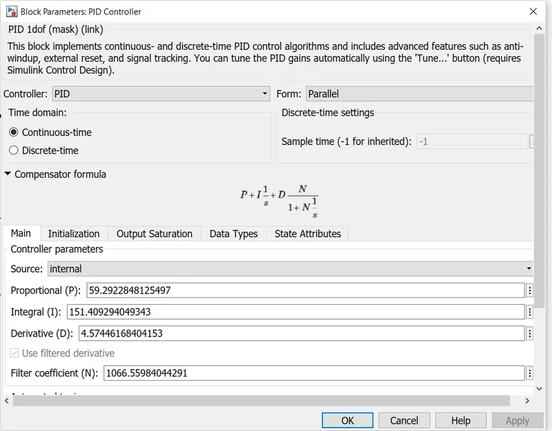
P = 59.29
I = 151.40
D = 4.57
Controller parameters:
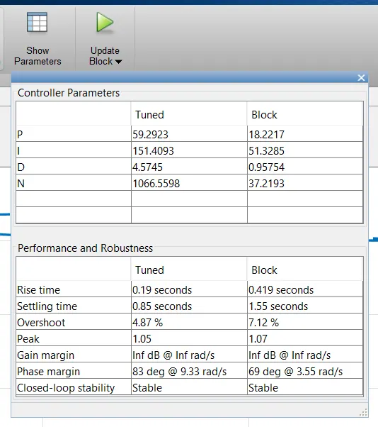
Tuned step response:
Update PID gain values after tuning:
Output Result:
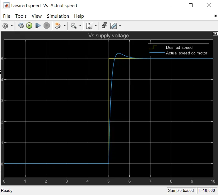
Here,actual speed of dc motor is equal to the desired speed of the dc motor response with less rise time and less overshoots.
Final plot:
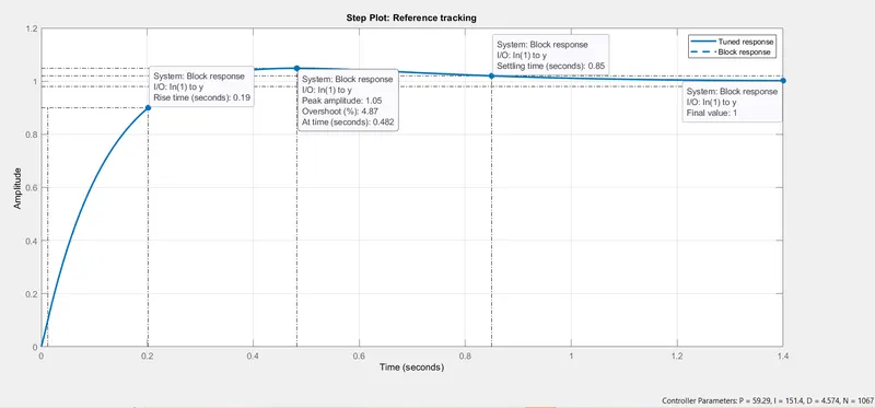
The below plot shows the step response with overshoot less than 5 % and setting time less than 2 secs and zero steady state error for the updated and tuned gain values
P = 59.29
I = 151.40
D = 4.57
Stability of the dynamic system:
The stability of the system is checked by giving the larger and different values of the input speed
Case 1:
For input speed of DC Motor 120 rad/s
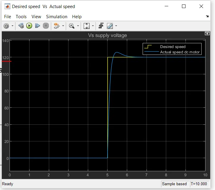
The output is tracked the input speed with the mentioned step response characteristics.
The desired speed of the DC motor is maintained.
Case 2:
For input speed of DC motor 230 rad/s
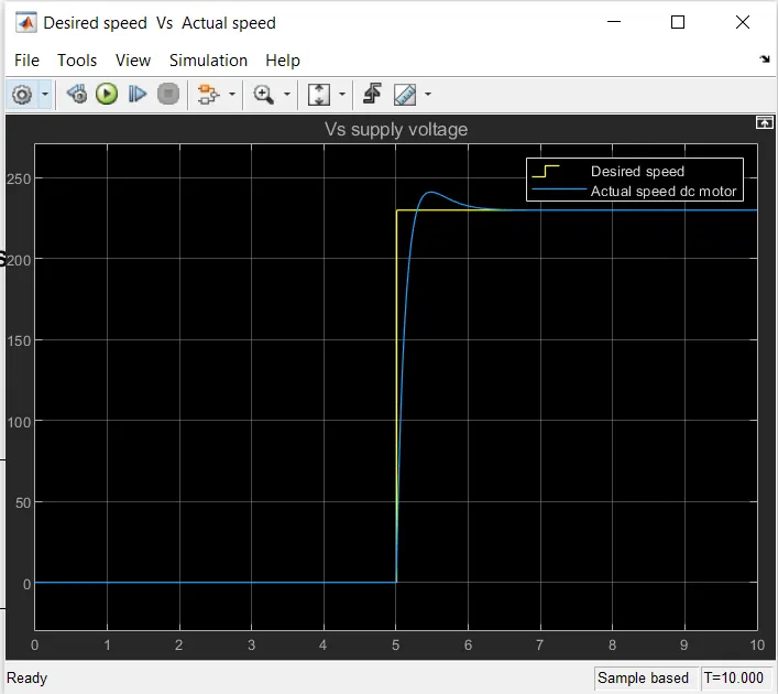
Even the speed of the motor is increased,the output speed is tracked the input speed with the mentioned step response characteristics.
The desired speed of the DC motor is maintained.
CONCLUSION:
The simulink model of DC motor for speed controlling using the PID controller is developed and the tuning is done to get the better tracking response and to maintain the speed control of DC motor.
The stability of the system is also analysed using the PID tuner and the desired and actual speed of the DC motor is observed.
Thank you
Submitted by
B.RIyaz