Project - Speed Control of a Direct Current (DC) motor
what is a PID controller?
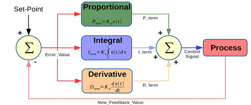
A proportional–integral–derivative controller (PID controller or three-term controller) is a control loop mechanism employing feedback that is widely used in industrial control systems and a variety of other applications requiring continuously modulated control.
BLOCKS USED
1)Sum: used for addition or subtraction of values
2) Gain: Used for multiplication purpose
3) Signal builder block: used to generate required signal
4) Integrator: Used for integration to find displacment from acceleration, velocity
5) Scope: Displaying result
6) Transfer function: used to create equations for transfer function
MODELING OF DC MOTOR
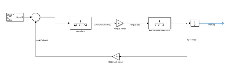
The DC motor consists of Applied voltage as input and angular velocity of the motor as output using appropriate equations we get the equation for transfer function as
`G(s)=(w(s))/(v(s))=(kt)/((Ls+r)(js+b)+kt*kb)`
MATLAB PROGRAM TO DETERMINE kp, kd and ki
clear all
close all
clc

% DESIGN PARAMETER FOR DC MOTOR
% Momemt of inertiaa of rotor in kg-m^2
j=0.01;
%Motor viscous friction constant in N-m-s
b=0.1;
%back EMF constant in v/rad/s
kb=0.01;
%Motor torque constant N-m/amp
kt=0.01;
%Resistance of the armature circuit in ohms
Ra=1;
%Inductance of the armature circuit in henries
La=0.5;
%transfer function
s=tf('s');
G=kt/((La*s+Ra)*(j*s+b)+kt*kb)

%determining stability
pzmap(G)
grid on
% determining the roots

z = 0.6;
f =1;
wn = 2*pi*f;
p1= -wn*z+wn*sqrt(z^2-1)
p2= -wn*z-wn*sqrt(z^2-1)
p = [p1 p2];

A=[-b/j kt/j; -kb/La -Ra/La]
B=[0 ; 1/La]
%place command computes a state-feedback matrix K such that
 %the eigenvalues of A-B*K are those specified in the vector P.
 k=place(A,B,p)
 kp=k(1);
 kd=k(2);
 ki=30;
DETERMINING STABILITY OF SYSTEM
Using pzmap(G) command we determine the stability of the sytem
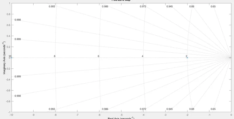
the values are in left hand plane so the system is stable
DESIGNING PID CONTROLLER FOR DC MOTOR
General schematics of a PID controller is shown below, we need to incorporate this into our previous simulink model.
SIMULINK MODEL OF ELECTRIC MODEL WITH PID CONTROL
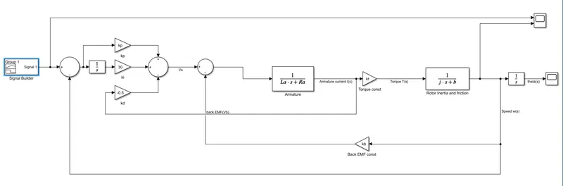
Here speed is the parameter we need to control so we take a feedback from speed (subract actual speed from reference speed) to determine the error. The feedback for kd is obtained from output current from the Model.
We need to check if we are are able trace the input with default Kp kd values and tune ki values, if we are not getting the required result fine tune Kp and kd also.
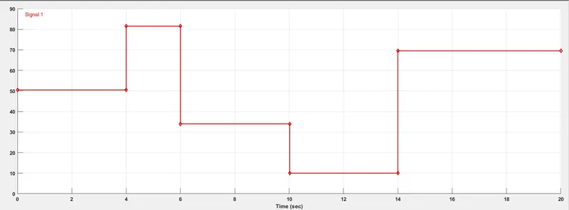
We are using a signal builder block with parameters shown below to create different signals which mimics different speed at different instant of time.
RESULT
CASE 1: kp and kd default value and fine tuning ki(ki=100)
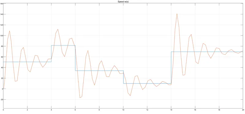
We can see that the system is not stable so we need to fine tune our kp
CASE 2: kp and kd default value and fine tuning ki(ki=30)
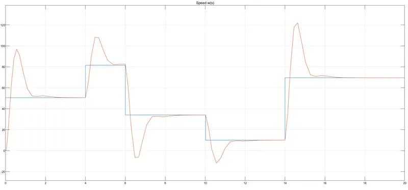
we can see that our system gets stable after certain oscillations and was able to reduce the rise time by decreasing ki values, but we need to prevent overshoot
case 3: kd default value, kp=25 and ki=30
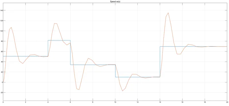
our system is not attaining the steady state by increasing or decreasing the kp value
CASE 4: kp default value ki=30 and fine tuning kd(kd=-0.5)
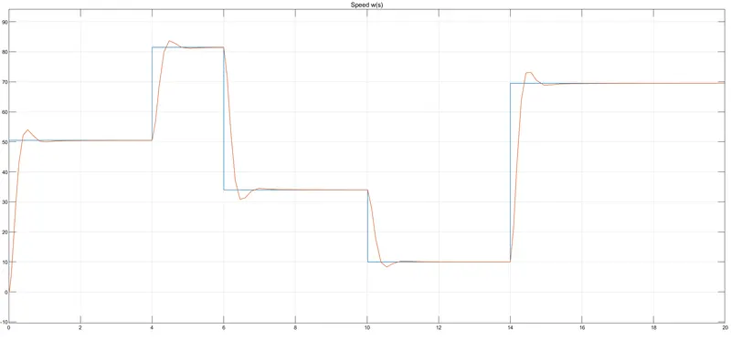
By increasing kd we were able to reduce our overshoot and made the input more tracable
RESULT
We have designed a PID controller for speed control of a motor and fine tuned its PID parameters so that the Signal builder (input speed) parameters are traced to the output, hence we are able to run our motor in desired speed.
REERENCE
https://ctms.engin.umich.edu/CTMS/index.php?example=Introduction§ion=ControlPID
https://ctms.engin.umich.edu/CTMS/index.php?example=MotorSpeed§ion=SystemModeling