Project - Speed Control of a Direct Current (DC) motor
PROJECT
In this project, a Simulink model for the DC motor will be first developed per the schematic shown in Figure 1.
Use the Proportional, Integral, and Derivative (PID) control design knowledge gained in the training to design, develop and test a controller to maintain a desired speed for the motor.
ANS:
To build a PID controller to regulate the speed of the DC motor we need to create a DC motor model which is given as
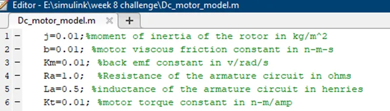
- The design parameters to model a DC motor has been declared in the matlab script file as follows
By using the given parameters a model for the DC motor is built in Simulink which is given as
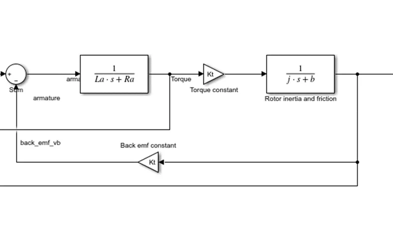
In order to build a DC motor in Simulink model first the input voltage or the armature current has been given to a matlab function block which will convert the armature current into torque
Here we are applying kirchoffs closed loop law to find the equation for converting voltage into current by using LAPLACE TRANSFORM
In Simulink it can be done by adding a transfer function block by giving the denominator values as Resistance( Ra) and Inductance (La)
By this operation we can obain the torque (t) values as we given the input armature current
Apply newton’s law to convert the torque into speed , in Simulink we can do this by adding a transfer function block by computing the moment of inertia of the rotor (Js )and damping constant (B)
Hence we can obtain speed as the output and it can be plotted out by using a scope block
In between a feedback voltage is fed back into the system which is known as back emf(vb) , a gain block is connected in between to find the back emf constant(Kb) ,
Thus the back emf constant can be calculated by partially derivating the back emf constant
Vb =Kb*w=Kb*d theta/dt
- Then a PID controller is added to the model to regulate the speed of the motor
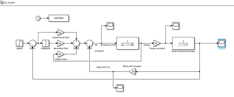
The PID controller is added to the model and the Proportional gain(Kp), Derivative gain(Kd) ,Integral gain(Ki) values has been found out by using PLACE command and is declared in the script file
- Step input is given as the input voltage unit with a value of 230 volts
- The integral gain value is varying such that we start by giving the (Ki) value as 400 ,so that we can found an output which is not stable ,then it is changed to 200 , so that we can find a better settling time and steady state error
- The output which is obtained is given as
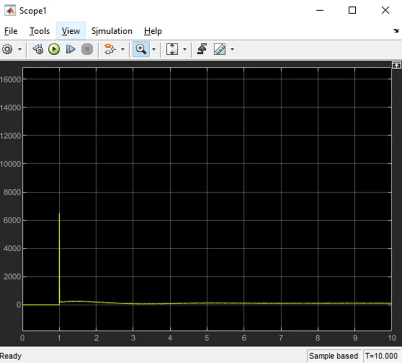
This is the output waveform of the armature current , here we can see a sudden overshoot and then the system is stabilized at a range of 100 amps
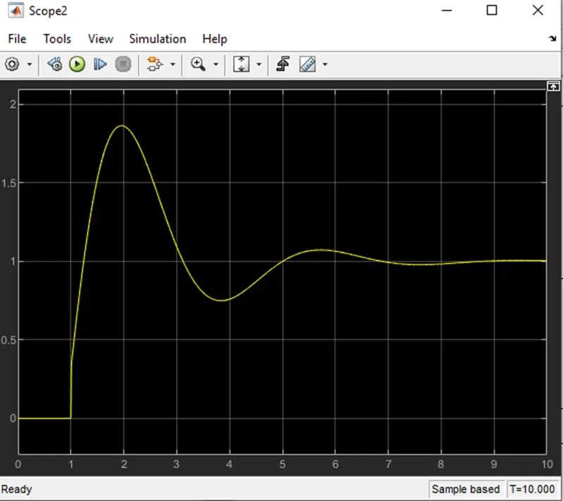
This is the waveform of torque , here a slight rise is obtained and then it is settled at a range of 1( N-m )
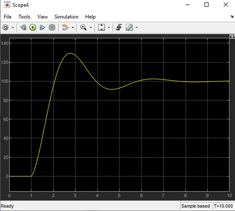
- Here we can obtain a better settling time and steady state error which is close to 100
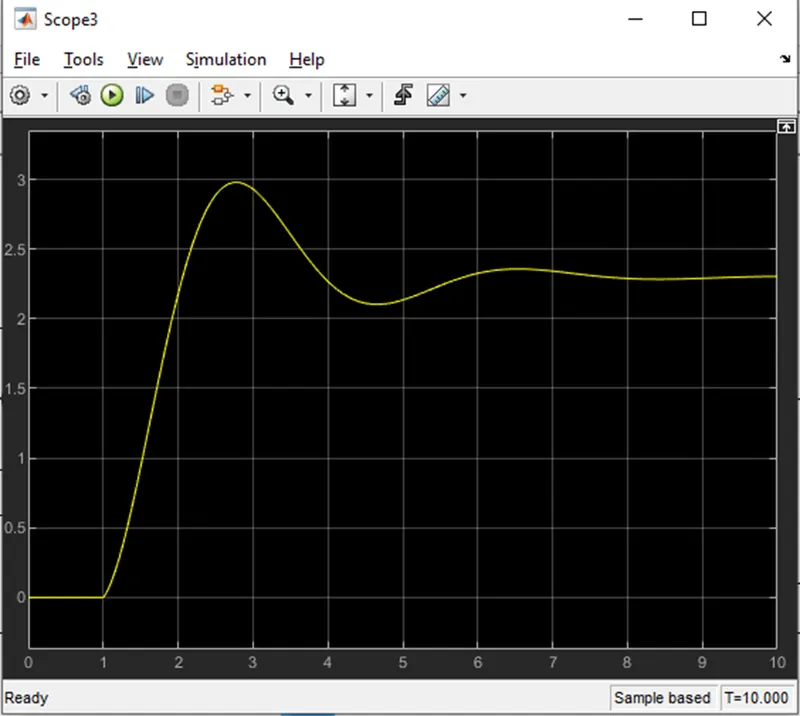
This is the output waveform of the back emf (vb)