Project - Position control of mass spring damper system
AIM: Obtain a transfer function of a mass spring damper system and use it in the model. Add a PID controller to adjust the force on mass so that its position follows a reference signal.
OBJECTIVE:
- Theory
- Simulink model
- Output
- Conclusion
THEORY:
The differential equation that governs the spring-mass system is:

MATLAB environment is conducive to matrix manipulations.
Any linear differential equation can be cast in a 'state-space representation' with input, output and state variables related by the first-order differential equations.
State-space representation of the above spring-mass system can be derived as the following.
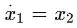
Let x = x1 and x_dot = x2, where x1 and x2 are the states that correspond to the position (also called displacement) and velocity of the spring-mass system, respectively.
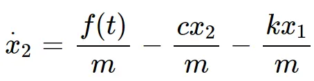
Let f(t) = u, where u is the input to the spring-mass system.
Let x = y, where y is the output from the spring-mass system.
The two first-order differential equations can be written:
or

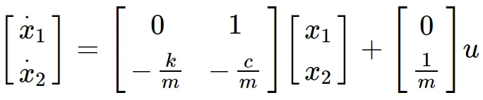
If we use matrix notation to represent these two first-order differential equations, we get:
and
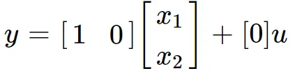
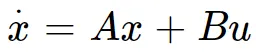
The above representation is called the state-space representation of the dynamic system and is generally shown as:
State equation
Output equation

If we substitute u = -Kx in the state equation
, we get

And if we can select the matrix, K, such that the eigenvalues of (A-BK) are negative and real with or without imaginary parts, then one can guarantee such a trajectory.
Now, let us begin the Simulink model.
SIMULINK MODEL:
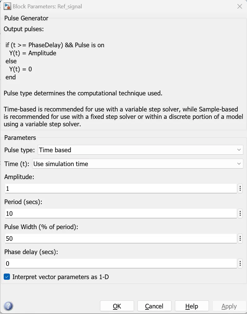
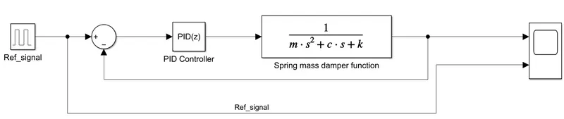
The Pulse Generator block generates square wave pulses at regular intervals. The block waveform parameters, Amplitude, Pulse Width, Period, and Phase delay, determine the shape of the output waveform.
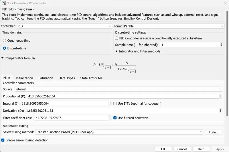
PID Controller block implements continuous- and discrete-time PID control algorithms, including advanced features such as anti-windup, external reset, and signal tracking.
I have tuned the PID Controller using the Tune button.
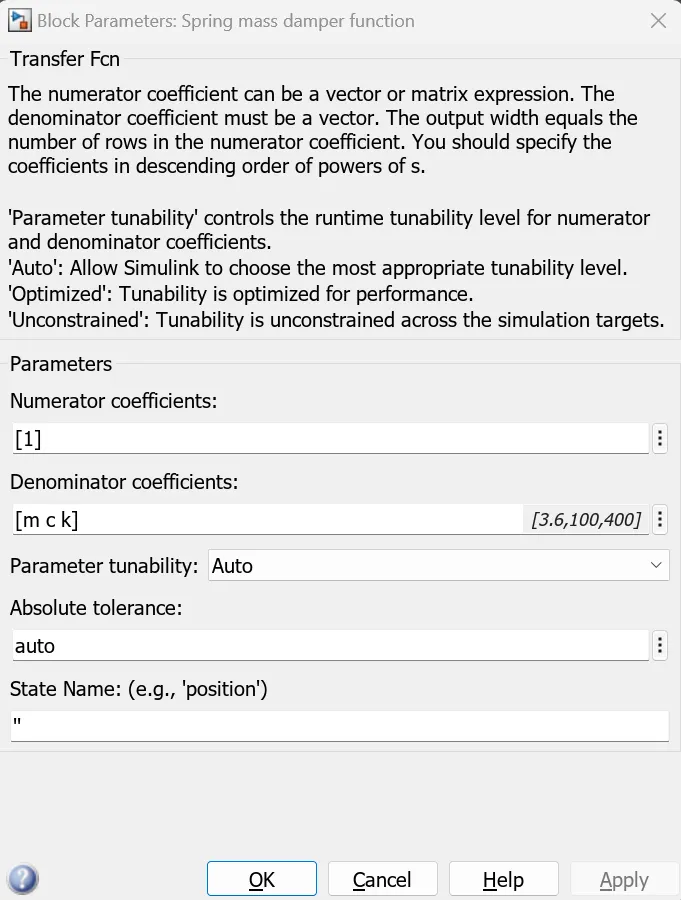
Transfer Fcn:
The numerator coefficient can be a vector or matrix expression. The denominator coefficient must be a vector. The output width equals the number of rows in the numerator coefficient. The coefficients should be specified in descending order of powers of s.
The overall model is built as shown below.
Output:
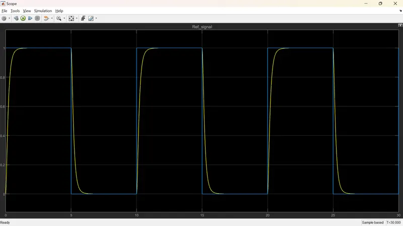
As we can see, the position of the spring mass damper system approximately follows the reference signal. Therefore, we can control the system by tuning the PID controller faster.
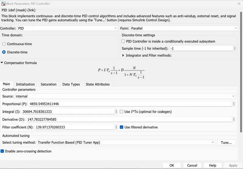
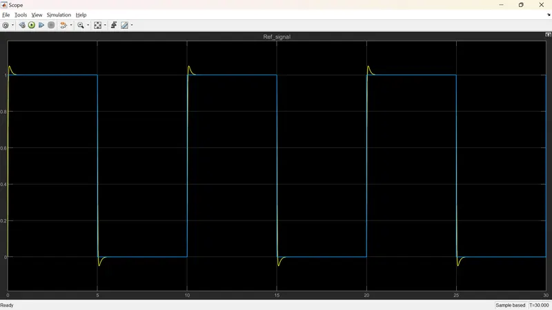
Here, the rise time is less than one second, the overshoot is less than 5%, and the settling time is less than two seconds.
Conclusion:
The transfer function of a mass spring damper system is obtained and used in the model. The PID controller is added to adjust the force on mass so that its position follows a reference signal.