Project - Analysis of a practical automotive wiring circuit
1. Identify each of the major elements in the above automotive wiring diagram ?
SOL: - The major elements in the automotive wiring diagram are
- Generator
- Battery
- Distributor
- Ammeter
- Horn
- Ground/Earth
- Indicating Light/Beam light
- Starter
- Breaker
- fuse
- Light Switch/Selector Switch
- Junction Block
2.Explain the purpose and working of any three elements briefly ?
sol:
1. Generator -
A generator, often referred to as a dynamo, is a vital device that transforms mechanical energy into electrical power. Its primary purpose is to generate electricity for transmission and distribution across power lines, providing electricity to residential, commercial, and industrial consumers.
Types of Generators: Generators are broadly categorized into two fundamental types: AC (Alternating Current) generators and DC (Direct Current) generators.
AC Generator: AC generators, also known as alternators, play a pivotal role in supplying electrical power in various applications. They operate on the principle of electromagnetic induction and are further classified into two categories: induction generators and synchronous generators. One notable advantage of AC generators is their low maintenance due to the absence of brushes. They are also favored for their compact size in comparison to DC generators, and they exhibit lower power losses.
DC Generator: DC generators are commonly found in off-grid applications. They are categorized into three main types based on the development of their magnetic field in the stator: permanent-magnet generators, separately-excited generators, and self-excited generators. DC generators are known for their simplicity and are often used to drive large motors and devices requiring direct control. They mitigate voltage fluctuations by incorporating a set of coils around the armature for stable-state applications.
Components of Generators: Generators consist of several essential components, apart from the mainframe, which can be grouped into four main categories:
-
Engine: The engine is a critical component that converts various fuels, such as gasoline, diesel, natural gas, propane, bio-diesel, or others, into mechanical energy. This mechanical energy serves as the input that the generator then transforms into electricity. Engine types used in generator designs include reciprocating, steam, turbine engines, and microturbines.
-
Fuel System: The fuel system gathers and pumps fuel to the engine. It typically includes a fuel tank capable of storing enough fuel to power the generator for a specified duration. Pipes connect the fuel tank to the engine, with a return pipe for excess fuel.
-
Alternator and Voltage Regulator: The alternator is a crucial component responsible for converting the mechanical energy produced by the engine into electrical current. It comprises the stator, a set of stationary coils, and the rotor (or armature), which generates a stable rotating electromagnetic field around the stator. Voltage regulation is essential to produce a consistent electrical current suitable for practical applications.
-
Cooling, Exhaust, and Lubricating Systems: These systems work together to ensure the generator's optimal performance and longevity. The cooling system prevents overheating by regulating component temperatures through methods like fans or coolants. The exhaust system disposes of harmful gases produced during combustion, while the lubricating system ensures the smooth operation of the generator's moving parts by providing adequate lubrication.
Conclusion: In this discussion, we've explored the essential aspects of generators, from their working principles and various types to the critical components that make them operational. Generators play a pivotal role in generating electricity from mechanical energy, making them indispensable in various applications across different sectors.
2. Battery -
Batteries are essential components that power a wide range of devices in our daily lives. They find applications across various sectors:
-
Automotive: Batteries are crucial for starting internal combustion engines and powering electric vehicles, primarily using lithium-ion technology.
-
Residential: In homes, batteries store energy from renewable sources like solar panels, reducing grid reliance and promoting sustainability.
-
Healthcare: Batteries are vital for medical instruments and implants, ensuring reliable operation during critical procedures.
-
Logistics and Construction: They power cordless tools, enhancing efficiency and mobility on job sites.
-
Emergency Services: Batteries are essential for emergency equipment like flashlights and communication devices.
-
Military: They power critical tools, enhancing situational awareness and operational efficiency.
-
Electric Vehicle Batteries: Specifically designed for electric cars, these batteries drive electric motors, reducing emissions.
In terms of their working principle, batteries store and convert chemical energy into electrical energy through electron flow and ion movement between electrodes and an electrolyte solution. Different materials and reactions affect battery performance and voltage.
- Working -
- A battery is a device that stores chemical energy and converts it to electrical energy.
- The chemical reactions in a battery involve the flow of electrons from one to another, through an external circuit.
- The flow of electrons provides an electric current that can be used to do work.
- To balance the flow of electrons, charged ions also flow through an electrolyte solution that is in contact with both electrodes.
- Different electrodes and electrolytes produce different chemical reactions that affect how the battery works, how much energy it can store and its voltage.
3. Ammeter-
An ammeter is an electrical instrument used to measure the flow of electric current in a circuit. Its primary purpose is to provide a quantitative measurement of the current, which is the rate of the flow of electric charge (typically measured in amperes or "amps").
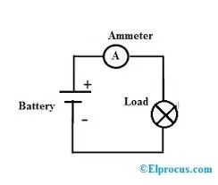
Working of an Ammeter:
-
Series Connection: Ammeters are connected in series within an electrical circuit, meaning that the current flows directly through the ammeter itself. This allows the ammeter to measure the current passing through the specific part of the circuit under investigation.
-
Low Resistance: Ammeters are designed with very low electrical resistance to ensure that they do not significantly alter the current being measured. Their low resistance ensures that most of the current flows through the ammeter, minimizing any voltage drop across the ammeter.
-
Reading Display: Ammeters typically have a scale or digital display that provides a direct readout of the current passing through the circuit. The scale is calibrated in amperes (amps), allowing the user to determine the exact current value.
Purpose of an Ammeter:
-
Current Measurement: The primary purpose of an ammeter is to measure the current flowing in an electrical circuit accurately. This is essential for various reasons, including safety, troubleshooting, and verifying that a circuit is operating within its specified current limits.
-
Circuit Analysis: Ammeters are valuable tools for analyzing and diagnosing electrical circuits. By measuring current at different points within a circuit, technicians and engineers can identify irregularities, such as overloads or short circuits, and take corrective actions.
-
Safety: Ammeters help ensure the safe operation of electrical systems. By monitoring current levels, they can detect abnormal or excessive current, which could indicate a fault or malfunction, allowing for timely intervention to prevent damage or hazards.
In summary, an ammeter is an essential instrument used to measure electric current in a circuit. It is connected in series to provide accurate readings and serves various purposes, including current measurement, circuit analysis, and safety monitoring.
3. If the total load is 10A from battery, what should be the fuse rating?
sol:
The fuse will blow as its primary function is to safeguard the wiring. Wires designed for a 5A circuit cannot handle a 10A current, so the 5A fuse will perform its duty by creating an open circuit, interrupting the flow of electricity. For a 10A load, it's recommended to use a 15A fuse. 10A is typically not a safe minimum as fuses are designed to limit current to prevent circuit damage from potential surges or even minor fluctuations. The fuse rating depends on factors like its frequency, ambient temperature, available fault energy, and inrush current, among others.
4. If 500W is the load, what is the voltage and capacity of battery you recommend ?
sol:
Step 1: Determine the Load and Voltage
- Given Load (P) = 500W
- Assumed Voltage (V) = 12V (a common voltage for batteries)
Step 2: Calculate Current (I) Using the Power Formula (P = VI)
- P = 500W
- V = 12V
- Using P = VI, you can rearrange the formula to solve for I:
- 500 = 12 * I
- Divide both sides by 12 to isolate I:
- I = 500 / 12
- Calculating this gives you:
- I = 41.67 amperes (A)
Step 3: Calculate Battery Capacity for One Day (24 Hours)
- Given Time (t) = 24 hours (1 day)
- Use the capacity formula: capacity = current × time
- Capacity = 41.67 A × 24 hours
- Calculating this gives you:
- Capacity = 1000.08 ampere-hours (Ah)
Step 4: Calculate Battery Capacity for One Month (720 Hours)
- Given Time (t) = 720 hours (1 month is typically 30 days, and each day has 24 hours)
- Use the capacity formula again:
- Capacity = 41.67 A × 720 hours
- Calculating this gives you:
- Capacity = 30002.4 ampere-hours (Ah)
So, for a load of 500W and a 12V source, i would recommended to use a battery with a capacity of approximately 1000.08 Ah for one day or 30002.4 Ah for one month to meet your power requirements.
5. Identify any two elements which are connected parallel to each other. Why they are connected in parallel ?
sol:
In electrical circuits, Two element which are connected in parallel are lamp and horn elements like lamps and horns can be connected in two primary ways: in series or in parallel. When elements are connected in parallel, it means that they share common voltage points, with each element having its own separate path for current to flow. This is in contrast to a series connection, where elements are connected end-to-end, and the same current flows through all of them.
6.Identify any two elements which are connected in series. Why they are connected in series ?
sol:
element are in series are ammeter and starter. Ammeter is connected in series becouse of current in series is constant and ammeter is measured current flow through circuit and second one is starter which is connected in series with motor armature winding across the circuit and restricte the current to an acceptable level, it also start the flow of current through a battery.
Certainly, let's reframe the answer:
Two elements that are connected in series are an ammeter and a starter. Here's why they are connected in series:
- Ammeter:
- An ammeter is connected in series within an electrical circuit because its primary function is to measure the current flowing through the circuit. When connected in series, the ammeter becomes part of the circuit's path, and all the current flows through it. This configuration allows the ammeter to provide an accurate reading of the current, as it directly measures the total current passing through that specific section of the circuit.
- Starter:
- The starter is connected in series with a motor's armature winding to achieve several important functions:
- Current Restriction: By being in series with the motor, the starter restricts the initial surge of current when the motor starts. This gradual increase in current helps protect the motor from damage and reduces stress on the electrical system.
- Controlled Activation: The starter acts as a switch, allowing the user to control when the motor starts. When the starter is engaged, it completes the circuit, allowing current to flow through the motor's armature and initiate its rotation.
- Safety: The series connection with the starter ensures that the motor only starts when intended, enhancing safety and preventing accidental activation.
- The starter is connected in series with a motor's armature winding to achieve several important functions:
In summary, both the ammeter and the starter are connected in series for specific reasons. The ammeter is connected in series to accurately measure current, while the starter is connected in series to control current flow and safely initiate motor operation.