Project - Analysis of a practical automotive wiring circuit
1. Identify each of the major elements in the above automotive wiring diagram.
Ans: The major elements in the above automotive wiring diagram are as follows:
- Battery
- Starter
- Ignition coil
- Generator
- Breaker
- Light switch
- Current and voltage regulator
- Foot selector switch
- Tail stop
- Parking lamp
- Horn
- Ammeter
- Ignition switch
- Dome light switch
- Gas tank unit
- Fuse
2. Explain the purpose and working of any three elements briefly.
Ans:
BATTERY: Batteries are the collection of one or more cells whose chemical reactions create a flow of electrons in a circuit. All batteries are made up of three basic components: an anode (the '-' side), a cathode (the '+' side), and some kind of electrolyte (a substance that chemically reacts with the anode and cathode).
Batteries that must be thrown away after use are known as primary batteries. Batteries that can be recharged are called secondary batteries.
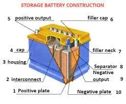
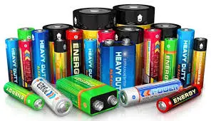
When the anode and cathode of a battery is connected to a circuit, a chemical reaction takes place between the anode and the electrolyte. This reaction causes electrons to flow through the circuit and back into the cathode where another chemical reaction takes place. When the material in the cathode or anode is consumed or no longer able to be used in the reaction, the battery is unable to produce electricity. At that point, your battery is "dead."
STARTER:
A starter (also self-starter, cranking motor, or starter motor) is a device used to rotate (crank) an IC engine so as to initiate the engine's operation under its own power. The starter can also be another internal-combustion engine in the case, for instance, of very large engines, or diesel engines in agricultural or excavation applications.
Internal combustion engines are feedback systems, which, once started, rely on the inertia from each cycle to initiate the next cycle. In a 4-stroke engine, the third stroke releases energy from the fuel, powering the fourth (exhaust) stroke and also the first two (intake, compression) strokes of the next cycle, as well as powering the engine's external load. To start the first cycle at the beginning of any particular session, the first two strokes must be powered in some other way than from the engine itself. The starter motor is used for this purpose and it is not required once the engine starts running and its feedback loop becomes self-sustaining.
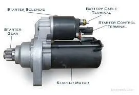
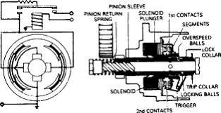
The working of a starter is quite easy and interesting, but most drivers really don’t know the secret behind motor cranking. When the ignition key or bottom is press, the transmission should be in park or neutral state. The battery voltage goes to through the starter control circuit to activates the solenoid.
The starter motor is powered by the solenoid, which helps to push the starter gear forward to mesh with the engine flywheel. This flywheel is mounted on the engine crankshaft, so as the starter motor spins it turns the flywheel so as the crankshaft. As soon as the engine start, the system disengages from the flywheel.
Note in an automatic transmission, starter motors can only be operated when the vehicle is in park or neutral position. And in manual transmission, the clutch pedal must be depressed.
The working inside the starter motor, there are four field windings attached to the housing from inside. The armature (rotating parts) is connected through the carbon brushes in series with the field coils. But remember in some starters field coils are replaced with magnet fields. There is a small gear at the front of the armature attached with an overrunning clutch.
IGNITION COIL:
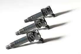
The air-fuel mixture is ignited in the combustion chamber by an ignition spark. In order for the spark plug to produce the spark, an ignition voltage of approx. 30,000 Volt is required. This voltage is generated by the ignition coil from the 12 Volt voltage of the vehicle electrical system and transferred to the spark plug at the moment of ignition. The ignition coil acts like a transformer. By means of two coils, one inside the other, the ignition coil transforms the electrical energy from the vehicle battery into high voltage, saves it briefly and then emits it as a high voltage current pulse to the spark plug.
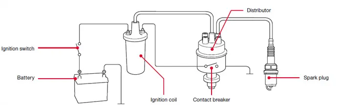
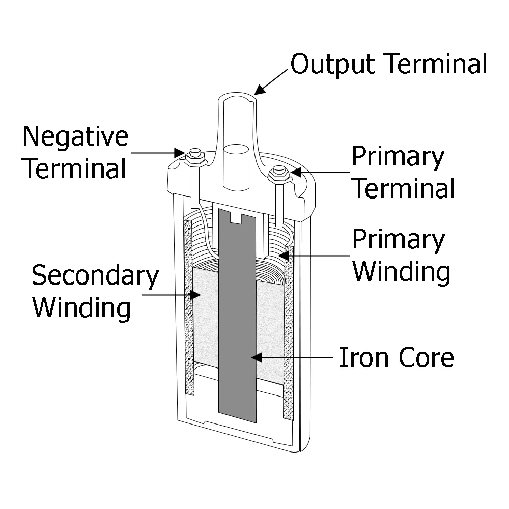
When the ignition switch is ON, the current through the primary winding starts to flow, this creates magnetic field in the iron core and around it.
As contact breaks in the contact breaker, the primary current collapses. This also collapses the magnetic field in the core. This sudden breaking of the magnetic field induces a very high voltage across the secondary winding. The magnitude of the voltage induced is about 50000 Volt.
This high voltage then is transferred to the spark plug through the ignition distributor to produce spark for the ignition.
It is mostly used in automobile ignition system and in those vehicles which is run by petrol engines such as scooter, motorcycles, cars etc. It is not used in the vehicles running form diesel engine.
3. If the total load is 10A from battery, what should be the fuse rating?
Ans: In the field of electrical engineering, a fuse is a device that provides overcurrent protection to the functional electrical circuit. Here, we have listed a few major functions of the fuse.
- Acts as a barrier between the electric circuit and the human body
- Prevents device failure due to faulty circuit operation
- Fuse prevents short-circuits
- Prevents overload and blackouts
- Prevents damage that is caused due to mismatched loads
The markings on the fuse carry information such as the Ampere rating, voltage rating, and interruption rating.
In order to select the right amperage of the fuse, we first need to know the full-load steady-state current of the circuit at an ambient temperature of 25º C (68º F). Once the current value is determined, then a fuse rating should be selected as to be 135% of this
value (taken to the next standard value).
As per given question, if the total load is 10 amps from battery,
[10 amps x 135% = 13.5 amps, the next larger standard size is 15A].
A 15A fuse rating should be selected.
4. If 500W is the load, what is the voltage and capacity of battery you recommend?
Given: Load = 500W, battery voltage =12V
To find: Recommended voltage and capacity of battery
Solution: Power = V X I
500 = 12 x I
I = 500/12
I = 41.67 A
charge capacity = Current x time
= 42 x 1………………… (assuming time for 1 hour)
= 42 Ah
Battery capacity = charge capacity x voltage
= 42 x 12
Ans: Battery capacity = 504 Wh.
5. Identify any two elements which are connected parallel to each other. Why they are connected in parallel?
Ans: The elements which are connected in parallel are as follow:
- Tail stop
- Sealed beam
- Dome light
- Plastic light
- Horn
- Parking lamp
battery to lights, beam and horn are connected parallel to each other. If two or more components are connected in parallel, they have the same difference of potential voltage across their ends. The potential differences across the components are the same in magnitude, and they also have identical polarities. The same voltage is applied to all circuit components connected in parallel.
6. Identify any two elements which are connected in series. Why they are connected in series?
Ans: Fuse and Stop Light Switch are connected in parallel. A series circuit is a closed circuit where the current follows one path. In a series circuit, the devices along the circuit loop are connected in a continuous row, so that if one device fails or is disconnected, the entire circuit is interrupted. Thus, all devices along the circuit stop working at the same time. In this given circuit it is connected in series because in case of any overload current than rated current or short circuit in circuit, before that current going to the Stop light switch it will first flow through fuse. It ensures safety of circuit from short circuit.