Project - Analysis of a practical automotive wiring circuit
ANALYSIS OF PRACTICAL AUTOMOTIVE CIRCUIT
OBJECTIVE:
- Identify each of the major elements in the above automotive wiring diagram.
- Explain the purpose and working of any three elements briefly.
- If the total load is 10A from battery, what should be the fuse rating?
- If 500W is the load, what is the voltage and capacity of battery you recommend?
- Identify any two elements which are connected parallel to each other. Why they are connected in parallel?
- Identify any two elements which are connected in series. Why they are connected in series?
INTRODUCTION:
AUTOMOTIVE WIRING CIRCUIT:
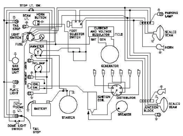
The above circuit diagram shows the connection of automotive wiring, It consists of battery,starter,generator,ignition coil,distributor,sealed beam lights,horns,plate lights,dome lights,tail lights,gas tank,ammeter,ignition switches,light switches and fuse.
The battery is connected to the starter, the starter starts the engine when the ignition switch is on,the ignition coil is connected to the circuit breaker and distributor, where the ignition coil work by transformer induction principle which gives the ignited current to the distributor which distributes the ignited current to the different plugs using the ignition time.Circuit breaker breakes the circuit by cam operation which operates the ignition coil.
Ammeter is connected in series with the battery to measure the current and generator is connected to the current and voltage regulator which regulates the voltage and current flow and give protection.Generator converts the mechanical energy into electrical energy which is used to charge the battery and running the vehicle auxillary systems.
foot selector switch is connected with the sealed beam bulb to adjust and turn it on and off,dome light switches and stop light switches are added and connected separetely with the dome lights and stop lights.Fuse is connected with light switches for overcurrent protection.
Fuel gauge is connected with the gas tank which shows the fuel level,Horns are connected with horn buttons in parallel connections.
These are the connections given in the automotive wiring circuit.
1.Identify each of the major elements in the above automotive wiring diagram.
The major elements in the above automotive wiring diagram are:
- Generator
- Starter
- Battery
- Ignition coil
- Circuit Breaker
- Distributor
- Current and Voltage regulator
- Ignition switch
- Fuse
- Ammeter
- Foot selector switch
- Gas tank unit
- Light switch
- Lamps
- Horns
2.Explain the purpose and working of any three elements briefly.
Generator:
Automobile generator - a unit that converts mechanical energy into electrical energy and performs the following functions:
- provides a constant and continuous battery charge when the engine is running;
- provides power to all systems during engine start, when the starter consumes a large amount of electricity.
It works exclusively when the internal combustion engine is on and is needed for:
- Recharge the battery;
- Provide sufficient energy for each unit of the machine's electrical system;
- In emergency mode or at maximum load, perform both functions - and feed the battery, and provide energy to the vehicle's electrical system.
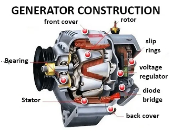
The generator working:
when the key is turned in the ignition lock, the mains is turned on. The voltage from the battery goes to the regulator, which in turn transfers it to the copper slip rings, the final consumer is the rotor excitation winding.
From the moment the engine crankshaft rotates, the rotor shaft begins to rotate through the belt drive, an electromagnetic field is created. The rotor generates an alternating current, when a certain speed is reached, the excitation winding is powered from the generator itself and not from the battery.The alternating current then flows to the diode bridge, where the “equalization” process takes place. The voltage regulator monitors the operating mode of the rotor, if necessary, changes the voltage of the field winding. Thus, provided that the parts are in good condition, a stable current is supplied to the battery, providing the on-board network with the required voltage.
Starter:
A starter or starter motor is an electrical device that used to rotate (crank) internal combustion engines so as to initiate the engine’s operation under its own power. As soon as the engine begins to run, it got disconnected from the engine, which now relies on the combustion process. The component is mounted on the engine’s gearbox housing, and the starter motor gear meets flywheel’s teeth.
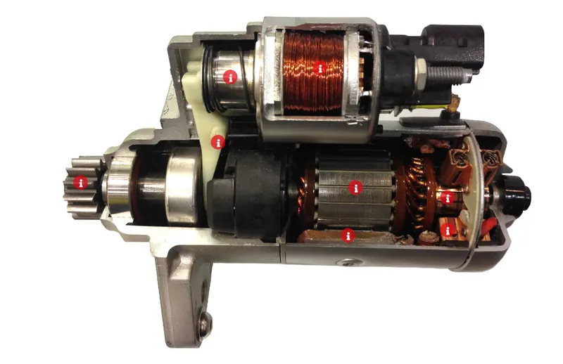
Working:
Being an electrical component, a starter consists of a powerful DC (Direct Current) electric motor and a solenoid. The solenoid receives positive power direct from the battery and hearth current from the engine body. In order to turn the engine, a 12-volt battery must be used to run the starter. This means the battery has to be sufficient enough to power the device.
When the ignition key or bottom is press, the transmission should be in park or neutral state. The battery voltage goes to through the starter control circuit to activates the solenoid. The starter motor is powered by the solenoid, which helps to push the starter gear forward to mesh with the engine flywheel. This flywheel is mounted on the engine crankshaft, so as the starter motor spins it turns the flywheel so as the crankshaft. As soon as the engine start, the system disengages from the flywheel.
Ignition coil:
An ignition coil (also called a spark coil) is an induction coil in an automobile's ignition system that transforms the battery's voltage to the thousands of volts needed to create an electric spark in the spark plugs to ignite the fuel.
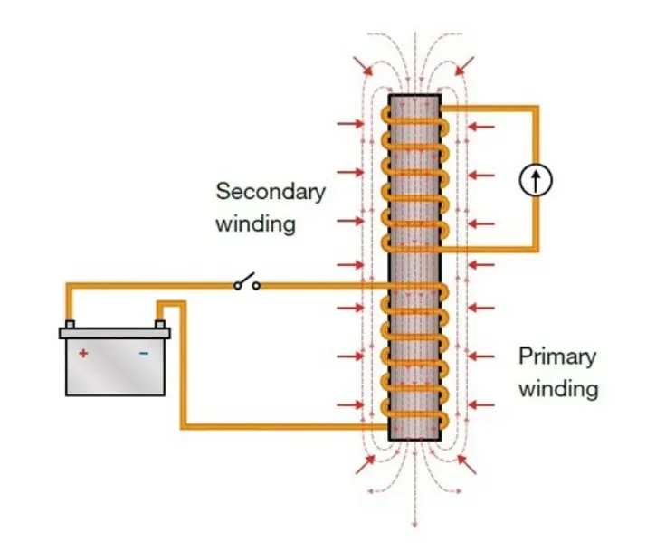
Working:
To produce the required high voltages, ignition coils make use of the relationships that exist between electricity and magnetism.When an electric current flows through an electrical conductor such as a coil of wire, it creates a magnetic field around the coil. The magnetic field (or, more precisely, magnetic flux) is effectively a store of energy, which can then be converted back into electricity.
If two coils of wire are placed next to or around each other and an electric current is used to create a magnetic field around one coil (which we call the primary winding), the magnetic field will also surround the second coil (or secondary winding). When the electric current is switched off and the magnetic field then collapses, it will induce a voltage into both the primary and the secondary windings. This is known as ‘mutual inductance’.
The magnetic field is initially created when the vehicle’s electrical system applies approximately 12 volts to the ignition coil’s primary winding. When a spark is required at a spark plug, the ignition system will switch off the current flow to the primary winding, which will cause the magnetic field to collapse. The collapsing magnetic field will induce a voltage into the primary winding in the region of 200 volts; but the voltage induced into the secondary winding will be approximately 100 times greater, around 20,000 volts.
By using the effects of mutual inductance and by using a secondary winding that has 100 times more windings than the primary winding, it is therefore possible to transform the original 12-volt supply into a very high voltage.
3. If the total load is 10A from battery, what should be the fuse rating?
Fuse:
A fuse is an electrical safety device that operates to provide overcurrent protection of an electrical circuit. Its essential component is a metal wire or strip that melts when too much current flows through it, thereby stopping or interrupting the current.
Fuse rating:
Fuse rating will be calculated based on the Power and Voltage the load works.
Power(watts) = Voltage(v) x Current(A)
Here the total load is 10 A, Normally fuse rating will more than the maximum ampere used by the load
So, we can take the fuse rating as 13-15A fuse.
4.If 500W is the load, what is the voltage and capacity of battery you recommend?
Given:
load power = 500W
To find:
Voltage(V)
Capacity(Ah)
Solution:
Assume 500W load is need for the system for 1 hour
Energy need E = Power x time
= 500 W x 1 h
E = 500Wh
Assume 12 V is recommended for this operation
Battery Capacity Q = E/V
Q - Battery capacity (Ah)
E- Enery needed to supply by the battery (Wh)
V- Voltage of the battery
Q = E/V
= 500/12
Q =41.66 Ah
Battery capacity needed is 41.6 Ah
60Ah battery is standard battery available.
So, the recommended battery voltae and capacity is 12V 60Ah battery.
5. Identify any two elements which are connected parallel to each other. Why they are connected in parallel?
Horn button with horns:
Horn button with horns is connected in parallel,because it is operate in same voltages but in different currents.
Light switch with the lights:
Light switch is connected with parallel to all the lights,because each light requires different power.
6. Identify any two elements which are connected in series. Why they are connected in series?
Battery and Ammeter:
The battery is connected to the Ammeter in series to measure the current from the battery, In series connection current is same.
Battery and Starter:
Battery and starter are connected in series because the starter needs the direct and high current from the battery.
Conclusion:
Practical Automotive wiring circuit is studied and analyzed.
Thank you