Project - Analysis of a practical automotive wiring circuit
The given automobile wiring circuit is related to the vehicle consisting of six cylinder, spark ignition, internal combustion engine. I was identified this as an internal combustion engine automobile by observing that, it was consisting of ignition switch, ignition coil, distributor and spark plugs.
Question 1:
The major elements in the above automotive wiring circuit are -
- Battery
- Starter
- Generator
- Current and voltage regulator
- Ignition switch, ignition breaker and ignition coil
- Distributor and spark plugs
- Ammeter
- Fuse
- Fuel gauge
- Switches
- Auxiliary equipments like lights and horn
- Cables and wire connectors
Question 2:
Purpose of elements-
Current and Voltage regulator -
The main purpose of this is to control the voltages across the circuit and to safeguard the generator, battery and auxiliary equipments. Typically, most of these are a three-unit regulators consisting of cutout relay, current regulator and voltage regulator.
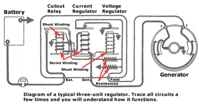
The cutout relay is also called as circuit breaker, which connects the generator to the battery circuit when the generator's voltage builds up to the desired value. It disconnects the generator when it slows down or stops.
Voltage regulator is used to regulate the maximum and minimum voltage at all times.
Current regulator is used to control the overheating caused by regulating the voltages, which causes currents to build up in the circuit. It is incorporated to prevent the premature failure
Ignition coil-
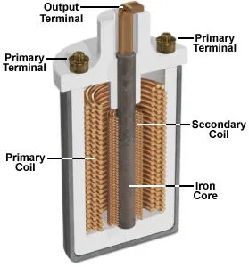
The air fuel mixture is ignited in the combustion chamber by an ignition spark. In order for the spark plug to produce the spark, an ignition voltage of approx 30,000 volts is required. This voltage is generated by the ignition coil from the 12 volt battery and is transferred to the spark plug at the time of ignition with the help of the distributor. The ignition coil acts like a transformer. By means of two coils, one inside the other, the ignition coil transforms the electrical energy from the vehicle's battery into high voltage, saves it briefly and then emits it as a high voltage current pulse to the spark plug.
Generator -
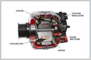
The alternator or generator is to distribute electricity to the car and recharge the battery. The mechanical energy from the engine is transferred to the generator through the belt and runs the rotor of the generator at high speed within the stator. Electricity is made as the rotor spins.
Question 3:
Given data, Load is `10A`
Fuse rating is given as 150% of full load current
`:.`Fuse rating `= 1.5xx10 = 15 Amp`
Fuse rating is `15A`
Question 4:
Given data
Load `= 500W`
Current `= 10A`
To find the voltage
we know that, Load = Current `xx` Voltage
`P = VxxI`
`:. 500 = Vxx10`
Voltage `V = 50 V`
To find the battery capacity
we know that, charge `q = Ixxt`
let, assume battery is fully charged in 3 hours
`:.`Capacity of the battery `= 10xx3`
Capacity `= 30Ah`
Question 5:
The parallel circuits are used mostly because, the operation of one circuit does not affect the operation of any other parallel circuit. Also, any circuit in parallel may be switched on or off without impacting the operation of any other circuit, and fault in any circuit need not. Series circuit is not used here because, one burnt out lamp filament or break in a wire would open the circuit and no lights and in that circuit would function. The elements which are connected in parallel are
Spark plugs - These are connected parallelly because it requires more voltage, and it is accumulated and released once to the spark plug. These are connected in series due to rise in breakdown voltage.
Beam lights - Headlights of the car are connected in parallel. In parallel connection, each headlight is exposed to the full potential difference supplied by the car's electrical system, giving the maximum brightness.
Horn - To achieve maximum tunes, we require maximum voltages which can be obtained in the parallel circuit.
Question 6:
The elements which are connected in series are
Ammeter - It is used to measure the current in the circuit. So it is connected in series so that the same current that is there in the circuit flows through it and gets measured.
Fuse - Fuse are always connected in series with the components to be protected from over current so that when the fuse blows it will open the entire circuit and stop current through the components.
Thank you