Project
Our aim is to Carry out a system-level simulation of an all-terrain vehicle.
Approach
I first started by downloading the file by given url, then I run that simulation here are what I came across.
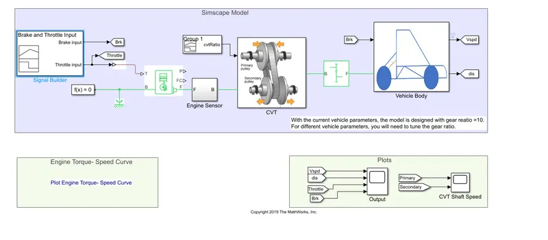
Here Starting with Signal builder with named "brake and throttle input" with 2 outputs, first port is connected with goto block named "Brk" & second port is connected with simulink-PS converter along with a goto block named "Throttle". Inside of signal builder is given below.
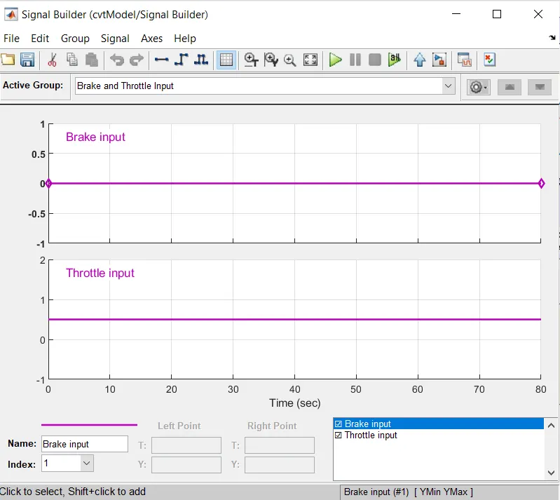
given in figure brake is 0 and throttle varies between 0 to 1
Further PS block is connected with T port of generic engine. Now I am going to show generic engine.
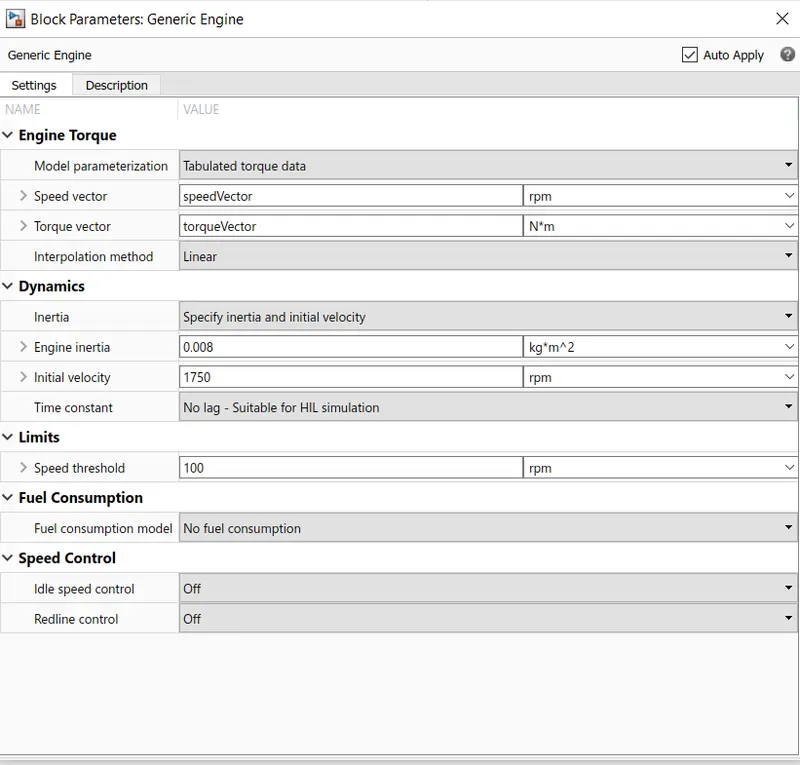
here all the parameters are already setup by default , the B port of generic engine is connected to mechanical reference and a solver, the F port of engine goes to engine sensor.
Now we will deal with engine sensor block, so here is diagram.
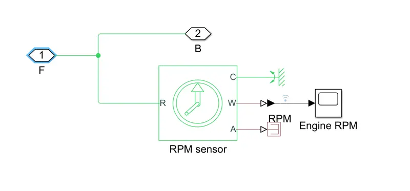
Inside the sensor there is rpm sensor with angular velocity is connected to scope named "Engine RPM". C is connected to angular rotational reference.
NOW SOME DETAILS ABOUT RPM SENSOR:-
This block measures angular velocity or angle in a mechanical rotational network. The sensor is ideal since it does not account for inertia, friction, delays, energy consumption, and so on.
The physical signal ports W and A report the angular velocity and angle, respectively, of port R relative to port C. The measured angular velocity is positive when the angular velocity at port R is greater than the angular velocity at port C.
After that we deals with "cvt ratio signal builder". Lets see the graph of signal builder.
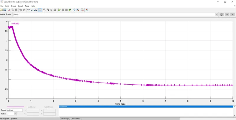
These points are shared by company & then by using these points signal builder is generated.
After that the signal from engine sensor and signalbuilder goes to CVT , therefore we will discuss CVT block.
Lets look inside CVT block.
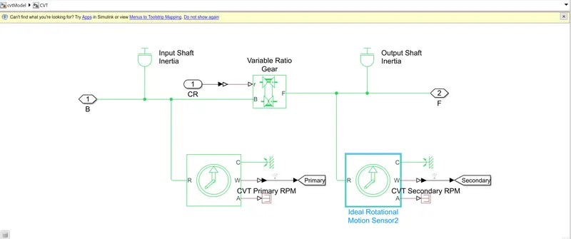
Start with "variable ratio gear" it is a variable ratio gearbox such as implemented by mechanical belt CVT, electric, or hydraulic transmissions. The physical signal input r defines the ratio of input to output angular shaft velocities.
Connections B (base) and F (follower) are mechanical rotational conserving ports. Specify the relation between base and follower rotation directions with the Output shaft rotates parameter.
Connecting inertial block with B Port variable ratio gear after that itwas connected one more inertial block to port F.Also we are going to see parameter of variable ratio gear.
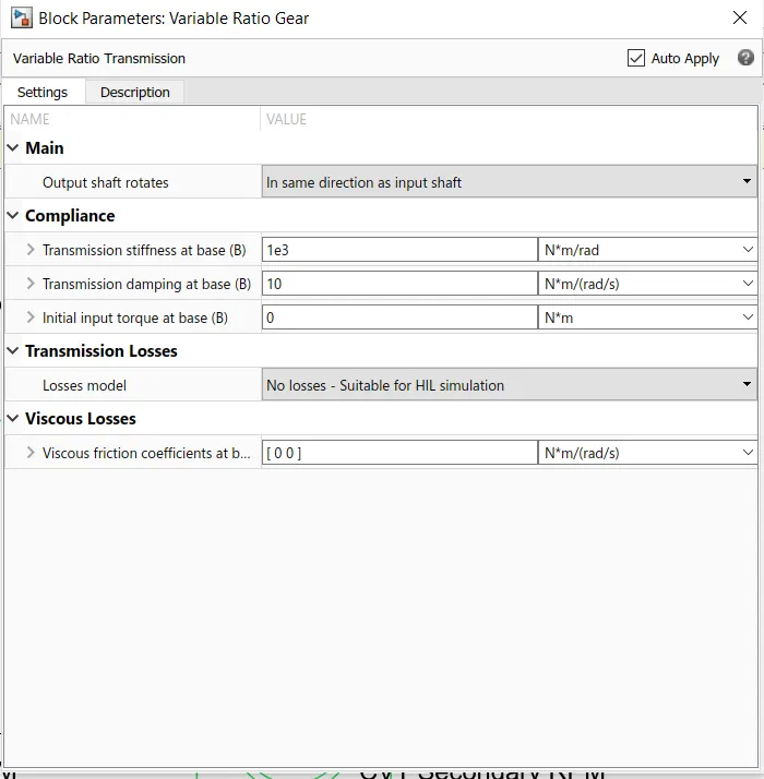
then 2 more ideal rotational sensor was connected one at B port and other at F port, which measure at two different spot.
After that we came out of box & move further to next block i.e simple Gear , lets see parameters of simple gear.
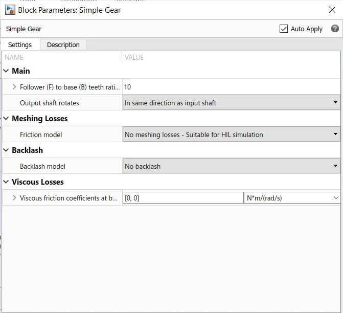
here the gear ratio is 10 & rest of the parameter is by default no change.
Represents a fixed-ratio gear or gear box. No inertia or compliance is modeled in this block. You can optionally include gear meshing, backlash, and viscous bearing losses.
Connections B (base) and F (follower) are mechanical rotational conserving ports. Specify the relation between base and follower rotation directions with the Output shaft rotates parameter. Optionally include thermal effects and expose thermal conserving port H by setting Friction model to a temperature-dependent setting.
After that we move to vehicle body, so lets look inside the vehicle block.
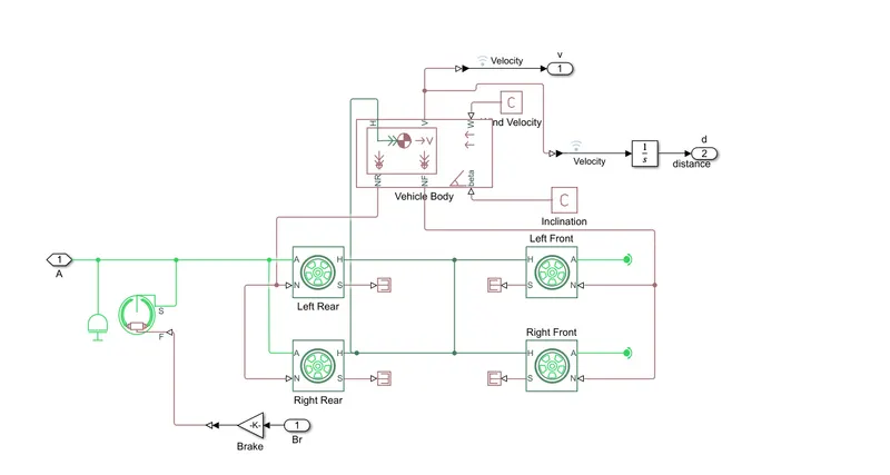
Now we will see inside componenent of vehicle body.
Starting with vehicle body so it,
Represents a two-axle vehicle body in longitudinal motion. The block accounts for body mass, aerodynamic drag, road incline, and weight distribution between axles due to acceleration and road profile. The vehicle can have the same or a different number of wheels on each axle. Optionally include pitch and suspension dynamics or additional variable mass and inertia. The vehicle does not move vertically relative to the ground.
Connection H is the mechanical translational conserving port associated with the horizontal motion of the vehicle body. The resulting traction motion developed by tires should be connected to this port. Connections V, NF, and NR are physical signal output ports for vehicle velocity and front and rear normal wheel forces, respectively. Wheel forces are considered positive if acting downwards. Connections W and beta are physical signal input ports corresponding to headwind speed and road inclination angle, respectively. If variable mass is modeled, the physical signal input ports CG and M are exposed. CG accepts a two- element vector representing the x and y distance offsets from vehicle CG to additional load mass CG. M represents the additional mass. If both variable mass and pitch dynamics are included, the physical signal port J accepts the inertia of the additional mass about its own CG.
Then Wind velocity block & inclination block goes to W port & delta port of block respectively.
The H port of vehicle block goes to common H port of tyre, after that NF port of vehicle body block goes to left front & right front tyre N port, while NR port of goes to left rear right rear tyre N port.
The V port of vehicle block goes to integration block as well as velocity signal.
The A port of all tyre goes to double shoe brake S port & F port of brake goes to gain port.
lets see brake parameter.
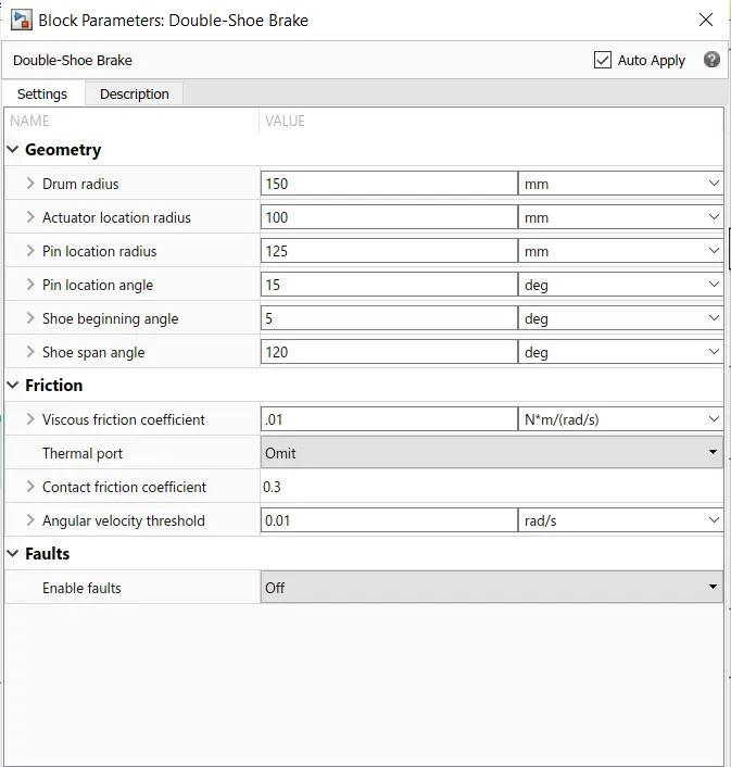
Now lets come out of all the sub-blocks & look at dashboard , so finally the last block of dashboard is vehicle body & in tis the inputs are brake "from" block , input from simple gear and the outputs are "Vspd & dis".
Now have a look on plots of different type:-
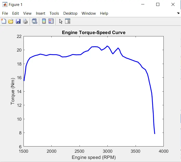
Engine Torque-Speed Curve
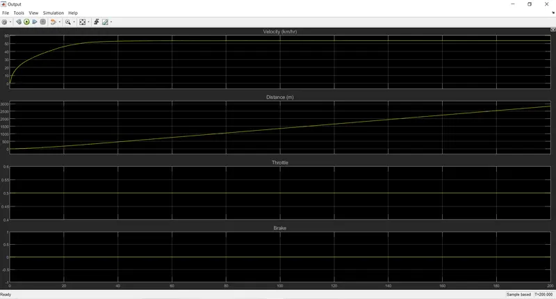
Speed displacement throttle brake
CVT shaft Speed
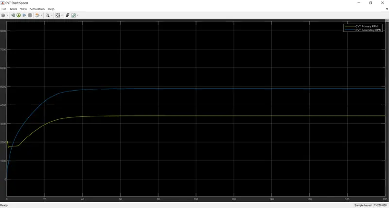
All the above graph clearly show all the datas we wants.